EP1249690A1 - Révélateur thermique - Google Patents
Révélateur thermique Download PDFInfo
- Publication number
- EP1249690A1 EP1249690A1 EP20010830280 EP01830280A EP1249690A1 EP 1249690 A1 EP1249690 A1 EP 1249690A1 EP 20010830280 EP20010830280 EP 20010830280 EP 01830280 A EP01830280 A EP 01830280A EP 1249690 A1 EP1249690 A1 EP 1249690A1
- Authority
- EP
- European Patent Office
- Prior art keywords
- temperature
- user
- vision
- environment
- field
- Prior art date
- Legal status (The legal status is an assumption and is not a legal conclusion. Google has not performed a legal analysis and makes no representation as to the accuracy of the status listed.)
- Withdrawn
Links
- 241001465754 Metazoa Species 0.000 claims abstract description 3
- 230000000007 visual effect Effects 0.000 claims abstract description 3
- 230000035945 sensitivity Effects 0.000 claims description 13
- 238000001514 detection method Methods 0.000 claims description 5
- 230000009977 dual effect Effects 0.000 claims description 5
- 239000004973 liquid crystal related substance Substances 0.000 claims description 3
- 238000006243 chemical reaction Methods 0.000 claims description 2
- 238000000034 method Methods 0.000 claims description 2
- 230000005670 electromagnetic radiation Effects 0.000 abstract description 4
- 230000003287 optical effect Effects 0.000 abstract description 2
- 238000007689 inspection Methods 0.000 abstract 1
- 230000005855 radiation Effects 0.000 description 5
- 238000004458 analytical method Methods 0.000 description 1
- 230000007423 decrease Effects 0.000 description 1
- 230000000694 effects Effects 0.000 description 1
- 238000011179 visual inspection Methods 0.000 description 1
Images
Classifications
-
- G—PHYSICS
- G01—MEASURING; TESTING
- G01J—MEASUREMENT OF INTENSITY, VELOCITY, SPECTRAL CONTENT, POLARISATION, PHASE OR PULSE CHARACTERISTICS OF INFRARED, VISIBLE OR ULTRAVIOLET LIGHT; COLORIMETRY; RADIATION PYROMETRY
- G01J5/00—Radiation pyrometry, e.g. infrared or optical thermometry
- G01J5/02—Constructional details
- G01J5/08—Optical arrangements
-
- G—PHYSICS
- G01—MEASURING; TESTING
- G01J—MEASUREMENT OF INTENSITY, VELOCITY, SPECTRAL CONTENT, POLARISATION, PHASE OR PULSE CHARACTERISTICS OF INFRARED, VISIBLE OR ULTRAVIOLET LIGHT; COLORIMETRY; RADIATION PYROMETRY
- G01J5/00—Radiation pyrometry, e.g. infrared or optical thermometry
- G01J5/02—Constructional details
- G01J5/025—Interfacing a pyrometer to an external device or network; User interface
-
- G—PHYSICS
- G01—MEASURING; TESTING
- G01J—MEASUREMENT OF INTENSITY, VELOCITY, SPECTRAL CONTENT, POLARISATION, PHASE OR PULSE CHARACTERISTICS OF INFRARED, VISIBLE OR ULTRAVIOLET LIGHT; COLORIMETRY; RADIATION PYROMETRY
- G01J5/00—Radiation pyrometry, e.g. infrared or optical thermometry
- G01J5/02—Constructional details
- G01J5/0265—Handheld, portable
-
- G—PHYSICS
- G01—MEASURING; TESTING
- G01J—MEASUREMENT OF INTENSITY, VELOCITY, SPECTRAL CONTENT, POLARISATION, PHASE OR PULSE CHARACTERISTICS OF INFRARED, VISIBLE OR ULTRAVIOLET LIGHT; COLORIMETRY; RADIATION PYROMETRY
- G01J5/00—Radiation pyrometry, e.g. infrared or optical thermometry
- G01J5/02—Constructional details
- G01J5/04—Casings
-
- G—PHYSICS
- G01—MEASURING; TESTING
- G01J—MEASUREMENT OF INTENSITY, VELOCITY, SPECTRAL CONTENT, POLARISATION, PHASE OR PULSE CHARACTERISTICS OF INFRARED, VISIBLE OR ULTRAVIOLET LIGHT; COLORIMETRY; RADIATION PYROMETRY
- G01J5/00—Radiation pyrometry, e.g. infrared or optical thermometry
- G01J5/02—Constructional details
- G01J5/08—Optical arrangements
- G01J5/0806—Focusing or collimating elements, e.g. lenses or concave mirrors
-
- G—PHYSICS
- G01—MEASURING; TESTING
- G01J—MEASUREMENT OF INTENSITY, VELOCITY, SPECTRAL CONTENT, POLARISATION, PHASE OR PULSE CHARACTERISTICS OF INFRARED, VISIBLE OR ULTRAVIOLET LIGHT; COLORIMETRY; RADIATION PYROMETRY
- G01J5/00—Radiation pyrometry, e.g. infrared or optical thermometry
- G01J5/0022—Radiation pyrometry, e.g. infrared or optical thermometry for sensing the radiation of moving bodies
- G01J5/0025—Living bodies
Definitions
- the device is an instrument able to locate in low visibility environment warm bodies, such as animals and humans.
- the device whose dimensions are about 15 x 5 x 4 cm, analyses environment temperature by a directive detector which detects electromagnetic radiation in thermal infrared band emitted by warm bodies.
- the device detects bodies having surface temperature higher than temperature of other bodies in the surrounding environment, even if light and colour conditions make them hard to locate by visual inspection.
- the device When in use, the device is pointed by the user toward a particular direction, and it measures mean temperature of the environment inspected in its field of vision. If the device detects a body warmer than surrounding environment it activates an optical indicator, a buzzer and a vibration motor.
- the devices existing for the same purpose can only detect time change in infrared radiation, so they must be kept continuously in motion by the user in order to convert a spatial difference of temperature in a time variation of radiation detected.
- This kind of device has the following limitations:
- the invention solves the problems previously described because it indicates the temperature of the observed environment, instead of detect only time change in temperature, and detects the presence of a warm body, notifying it to the user.
- This is possible thanks to numerical conversion of the electric signal produced by a pyroelectric detector sensible to the thermal infrared electromagnetic radiation, and using a microcontroller based decision system.
- the microcontroller detects the presence of a warm body analysing the signal produced by the detector and drives an indicator perceptible by the user.
- the pyroelectric detector generates an electrical signal when exposed to heat in the form of infrared radiation received within a view angle depending on detector size and lens focal length.
- the typical view angle is between 5 and 10 degrees, but it is possible to change it using a different lens or a different detector.
- the signal generated by the detector which is proportional to mean temperature of the bodies in the field of vision, is converted by an analog to digital converter and is managed by a microcontroller.
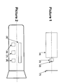
- the microcontroller manages three keys (6), (7), (8) used to control the device, a graphical indicator (5) (a LED bar or a liquid crystal display - LCD), a buzzer and a vibration motor used to indicate to the user the presence of a warm body in the field of vision of the instrument.
- a graphical indicator (5) a LED bar or a liquid crystal display - LCD
- a buzzer and a vibration motor used to indicate to the user the presence of a warm body in the field of vision of the instrument.
- the microcontroller processes the signal generated by the pyroelectric detector (converted in numerical format), whose amplitude is proportional to mean temperature of the environment included in the field of vision, with the following purposes:
- the device calibrates itself, that's to say it computes the mean temperature of the environment included in the field of vision and takes this temperature as a reference temperature.
- the microcontroller lights up a different LED on the bar (or shows a corresponding indication on the LCD) whose position is proportional to the difference between the temperature of the environment included in the field of vision and the reference temperature. This indication shows to the user the mean temperature of the bodies in the field of vision of the device.
- the microcontroller lights up all the LED in the bar and activates buzzer and vibration motor. Vibration motor and buzzer are deactivated when the observed environment temperature decreases and gets lower than reference temperature (plus the threshold temperature).
- the sensitivity of detection criterion that is the sensitivity to detect a body warmer than other objects in surrounding environment, depends on the value of threshold temperature. User has to calibrate the device each time the mean temperature of the environment changes quickly (for example, if it gets exposed to direct sun light) to avoid that quick increasing environment temperature could cause false indication of a warm body.
- the device slowly modifies reference temperature to make it equal to the mean temperature of the environment in the field of vision, computed in a time period of about 30 seconds. If this period is reduced the instrument is less sensible to false alarms caused by slow variation of environment temperature, and less sensible to detect warm bodies.
- the user can manage three keys (6), (7), (8), with the following purposes:
- the user has to press the key (8), which is also used to calibrate.
- the key (8) which is also used to calibrate.
- the user has to keep the key (7) pressed for more than one second.
- the user has to press key (7) several times.
- the user has to press several times the key (6), which modifies the dynamic of LED (or LCD) graphic indicator and the sensitivity of detection criterion previously described.
- the device Each time the user presses a key, the device indicates the status of battery charge, buzzer and vibration motor, by lighting up for one second one or more LED in the corresponding position near the graphic icons drawn on front panel.
- the devices shows to the user the sensitivity level selected by lighting up more than one adjacent LED (instead of one) during operation. If three sensitivity levels are allowed, when user has selected minimum sensitivity level only one LED is lighted in bar, when sensitivity is at medium level two LED are lighted, and when sensitivity is at maximum level three LED are lighted (in any case, when a warm body is detected all the LED in bar are lighted).
- a dual pyroelectric detector which contains two sensing elements on a horizontal plane (differential detection mode).
- This kind of detector produces an electric signal proportional to the difference between radiation detected by two elements, that is the difference between temperature of adjacent areas in the field of vision, one containing the target and the other used as a reference.
- this operating mode it isn't necessary to calibrate the device when the environment temperature changes, because it measures the difference between the temperature of two adjacent areas, which are characterized by the same temperature until a warm body is present in one of them.
- This operating mode is useful when frequent time change in mean environment temperature make the user frequently calibrate the instrument using single pyroelectric detector.
- a different shape of the device a different shape and position of keys and visual indicator (LED or LCD), a different logic to manage the keys described don't change the working principle of the device and don't bring innovation to it.
Applications Claiming Priority (2)
| Application Number | Priority Date | Filing Date | Title |
|---|---|---|---|
| ITRM200194 | 2001-02-22 | ||
| ITRM20010194 | 2001-04-13 |
Publications (1)
| Publication Number | Publication Date |
|---|---|
| EP1249690A1 true EP1249690A1 (fr) | 2002-10-16 |
Family
ID=11455442
Family Applications (1)
| Application Number | Title | Priority Date | Filing Date |
|---|---|---|---|
| EP20010830280 Withdrawn EP1249690A1 (fr) | 2001-04-13 | 2001-04-30 | Révélateur thermique |
Country Status (1)
| Country | Link |
|---|---|
| EP (1) | EP1249690A1 (fr) |
Citations (9)
| Publication number | Priority date | Publication date | Assignee | Title |
|---|---|---|---|---|
| US4225786A (en) * | 1978-09-15 | 1980-09-30 | Detection Systems, Inc. | Infrared detection system |
| EP0018033A1 (fr) * | 1979-04-12 | 1980-10-29 | Philips Electronics Uk Limited | Dispositifs détecteurs de rayonnements et arrangements de circuits comprenant ces dispositifs détecteurs de rayonnements |
| US4566808A (en) * | 1983-02-16 | 1986-01-28 | Exergen Corporation | Scanning radiation detector |
| JPH0252201A (ja) * | 1988-08-15 | 1990-02-21 | Daikin Ind Ltd | 人体位置検出装置 |
| JPH05113367A (ja) * | 1991-10-21 | 1993-05-07 | Yamatake Honeywell Co Ltd | 赤外線人検知センサ |
| US5352039A (en) * | 1990-08-06 | 1994-10-04 | Ortomedic | Remote temperature and/or temperature difference measuring device |
| JPH07318661A (ja) * | 1994-05-27 | 1995-12-08 | Matsushita Seiko Co Ltd | 人検知アルゴリズム |
| US5729019A (en) * | 1995-12-29 | 1998-03-17 | Honeywell Inc. | Split field-of-view uncooled infrared sensor |
| US5742055A (en) * | 1995-07-13 | 1998-04-21 | Lg Electronics Inc. | Device for sensing position of human body using infrared sensor |
-
2001
- 2001-04-30 EP EP20010830280 patent/EP1249690A1/fr not_active Withdrawn
Patent Citations (9)
| Publication number | Priority date | Publication date | Assignee | Title |
|---|---|---|---|---|
| US4225786A (en) * | 1978-09-15 | 1980-09-30 | Detection Systems, Inc. | Infrared detection system |
| EP0018033A1 (fr) * | 1979-04-12 | 1980-10-29 | Philips Electronics Uk Limited | Dispositifs détecteurs de rayonnements et arrangements de circuits comprenant ces dispositifs détecteurs de rayonnements |
| US4566808A (en) * | 1983-02-16 | 1986-01-28 | Exergen Corporation | Scanning radiation detector |
| JPH0252201A (ja) * | 1988-08-15 | 1990-02-21 | Daikin Ind Ltd | 人体位置検出装置 |
| US5352039A (en) * | 1990-08-06 | 1994-10-04 | Ortomedic | Remote temperature and/or temperature difference measuring device |
| JPH05113367A (ja) * | 1991-10-21 | 1993-05-07 | Yamatake Honeywell Co Ltd | 赤外線人検知センサ |
| JPH07318661A (ja) * | 1994-05-27 | 1995-12-08 | Matsushita Seiko Co Ltd | 人検知アルゴリズム |
| US5742055A (en) * | 1995-07-13 | 1998-04-21 | Lg Electronics Inc. | Device for sensing position of human body using infrared sensor |
| US5729019A (en) * | 1995-12-29 | 1998-03-17 | Honeywell Inc. | Split field-of-view uncooled infrared sensor |
Non-Patent Citations (3)
| Title |
|---|
| PATENT ABSTRACTS OF JAPAN vol. 014, no. 223 (P - 1046) 11 May 1990 (1990-05-11) * |
| PATENT ABSTRACTS OF JAPAN vol. 017, no. 474 (P - 1602) 27 August 1993 (1993-08-27) * |
| PATENT ABSTRACTS OF JAPAN vol. 1996, no. 04 30 April 1996 (1996-04-30) * |
Similar Documents
| Publication | Publication Date | Title |
|---|---|---|
| US8468874B2 (en) | Laser indicator for remote measuring devices and methods therefor | |
| JP5461470B2 (ja) | 近接度検出器 | |
| US8483991B2 (en) | Method and system for measuring thermal radiation to determine temperature and emissivity of an object | |
| US10965889B2 (en) | Thermal imager that analyzes temperature measurement calculation accuracy | |
| US20120320189A1 (en) | Thermal imager that analyzes temperature measurement calculation accuracy | |
| US20100179785A1 (en) | Temperature Measurement Instruments and Methods for Identifying a Selected Target Area | |
| EP2974046B1 (fr) | Dispositif portable à détection de température | |
| JP2015125670A (ja) | 画像投射装置 | |
| US8240912B2 (en) | Multi-zone non-contact spot thermometer | |
| TW200519721A (en) | Position detection device | |
| US4427888A (en) | Infrared imaging system | |
| JP2012117896A (ja) | 測距装置、侵入者監視装置、距離計測方法、及びプログラム | |
| CN109470284A (zh) | 一种背景抑制性光电传感器 | |
| CN202582734U (zh) | 一种红外测温仪 | |
| JP2007139596A (ja) | 可搬式運動計測システムおよび運動計測方法 | |
| EP1249690A1 (fr) | Révélateur thermique | |
| CN209166467U (zh) | 一种背景抑制性光电传感器 | |
| JP6593860B2 (ja) | 輝度分布センサ | |
| KR101488938B1 (ko) | 전자 디바이스의 전원 제어장치 | |
| JP4570839B2 (ja) | 光学式座標入力装置及び光学式座標入力方法 | |
| Ben-Ari et al. | Sensors | |
| KR20180092674A (ko) | Swir 대역에서의 표적 신호 측정 장치 및 방법 | |
| KR101707568B1 (ko) | 다용도 온도계 | |
| KR100781576B1 (ko) | 경사 감지 방법 및 이를 이용한 경사 감지장치 | |
| KR100404743B1 (ko) | 적외선 센서와 공간필터를 이용한 미세 동작 감지장치 |
Legal Events
| Date | Code | Title | Description |
|---|---|---|---|
| PUAI | Public reference made under article 153(3) epc to a published international application that has entered the european phase |
Free format text: ORIGINAL CODE: 0009012 |
|
| AK | Designated contracting states |
Kind code of ref document: A1 Designated state(s): AT BE CH CY DE DK ES FI FR GB GR IE IT LI LU MC NL PT SE TR |
|
| AX | Request for extension of the european patent |
Free format text: AL;LT;LV;MK;RO;SI |
|
| 17P | Request for examination filed |
Effective date: 20030205 |
|
| AKX | Designation fees paid |
Designated state(s): AT BE CH CY DE DK ES FI FR GB GR IE IT LI LU MC NL PT SE TR |
|
| 17Q | First examination report despatched |
Effective date: 20061107 |
|
| STAA | Information on the status of an ep patent application or granted ep patent |
Free format text: STATUS: THE APPLICATION IS DEEMED TO BE WITHDRAWN |
|
| 18D | Application deemed to be withdrawn |
Effective date: 20070320 |