EP1249669A2 - Ventilating system, heat exchanger, method of ventilating an enclosed space and method of making a plastic heat exchanger - Google Patents
Ventilating system, heat exchanger, method of ventilating an enclosed space and method of making a plastic heat exchanger Download PDFInfo
- Publication number
- EP1249669A2 EP1249669A2 EP02007370A EP02007370A EP1249669A2 EP 1249669 A2 EP1249669 A2 EP 1249669A2 EP 02007370 A EP02007370 A EP 02007370A EP 02007370 A EP02007370 A EP 02007370A EP 1249669 A2 EP1249669 A2 EP 1249669A2
- Authority
- EP
- European Patent Office
- Prior art keywords
- heat exchanger
- panels
- heat
- exhaust air
- fan
- Prior art date
- Legal status (The legal status is an assumption and is not a legal conclusion. Google has not performed a legal analysis and makes no representation as to the accuracy of the status listed.)
- Withdrawn
Links
Images

Classifications
-
- F—MECHANICAL ENGINEERING; LIGHTING; HEATING; WEAPONS; BLASTING
- F24—HEATING; RANGES; VENTILATING
- F24F—AIR-CONDITIONING; AIR-HUMIDIFICATION; VENTILATION; USE OF AIR CURRENTS FOR SCREENING
- F24F5/00—Air-conditioning systems or apparatus not covered by F24F1/00 or F24F3/00, e.g. using solar heat or combined with household units such as an oven or water heater
- F24F5/0007—Air-conditioning systems or apparatus not covered by F24F1/00 or F24F3/00, e.g. using solar heat or combined with household units such as an oven or water heater cooling apparatus specially adapted for use in air-conditioning
- F24F5/0035—Air-conditioning systems or apparatus not covered by F24F1/00 or F24F3/00, e.g. using solar heat or combined with household units such as an oven or water heater cooling apparatus specially adapted for use in air-conditioning using evaporation
-
- F—MECHANICAL ENGINEERING; LIGHTING; HEATING; WEAPONS; BLASTING
- F24—HEATING; RANGES; VENTILATING
- F24F—AIR-CONDITIONING; AIR-HUMIDIFICATION; VENTILATION; USE OF AIR CURRENTS FOR SCREENING
- F24F12/00—Use of energy recovery systems in air conditioning, ventilation or screening
- F24F12/001—Use of energy recovery systems in air conditioning, ventilation or screening with heat-exchange between supplied and exhausted air
- F24F12/006—Use of energy recovery systems in air conditioning, ventilation or screening with heat-exchange between supplied and exhausted air using an air-to-air heat exchanger
-
- F—MECHANICAL ENGINEERING; LIGHTING; HEATING; WEAPONS; BLASTING
- F28—HEAT EXCHANGE IN GENERAL
- F28D—HEAT-EXCHANGE APPARATUS, NOT PROVIDED FOR IN ANOTHER SUBCLASS, IN WHICH THE HEAT-EXCHANGE MEDIA DO NOT COME INTO DIRECT CONTACT
- F28D5/00—Heat-exchange apparatus having stationary conduit assemblies for one heat-exchange medium only, the media being in contact with different sides of the conduit wall, using the cooling effect of natural or forced evaporation
-
- F—MECHANICAL ENGINEERING; LIGHTING; HEATING; WEAPONS; BLASTING
- F28—HEAT EXCHANGE IN GENERAL
- F28D—HEAT-EXCHANGE APPARATUS, NOT PROVIDED FOR IN ANOTHER SUBCLASS, IN WHICH THE HEAT-EXCHANGE MEDIA DO NOT COME INTO DIRECT CONTACT
- F28D9/00—Heat-exchange apparatus having stationary plate-like or laminated conduit assemblies for both heat-exchange media, the media being in contact with different sides of a conduit wall
- F28D9/0081—Heat-exchange apparatus having stationary plate-like or laminated conduit assemblies for both heat-exchange media, the media being in contact with different sides of a conduit wall the conduits for one heat-exchange medium being formed by a single plate-like element ; the conduits for one heat-exchange medium being integrated in one single plate-like element
-
- F—MECHANICAL ENGINEERING; LIGHTING; HEATING; WEAPONS; BLASTING
- F28—HEAT EXCHANGE IN GENERAL
- F28F—DETAILS OF HEAT-EXCHANGE AND HEAT-TRANSFER APPARATUS, OF GENERAL APPLICATION
- F28F21/00—Constructions of heat-exchange apparatus characterised by the selection of particular materials
- F28F21/06—Constructions of heat-exchange apparatus characterised by the selection of particular materials of plastics material
- F28F21/065—Constructions of heat-exchange apparatus characterised by the selection of particular materials of plastics material the heat-exchange apparatus employing plate-like or laminated conduits
-
- F—MECHANICAL ENGINEERING; LIGHTING; HEATING; WEAPONS; BLASTING
- F28—HEAT EXCHANGE IN GENERAL
- F28F—DETAILS OF HEAT-EXCHANGE AND HEAT-TRANSFER APPARATUS, OF GENERAL APPLICATION
- F28F3/00—Plate-like or laminated elements; Assemblies of plate-like or laminated elements
- F28F3/02—Elements or assemblies thereof with means for increasing heat-transfer area, e.g. with fins, with recesses, with corrugations
- F28F3/04—Elements or assemblies thereof with means for increasing heat-transfer area, e.g. with fins, with recesses, with corrugations the means being integral with the element
-
- F—MECHANICAL ENGINEERING; LIGHTING; HEATING; WEAPONS; BLASTING
- F24—HEATING; RANGES; VENTILATING
- F24F—AIR-CONDITIONING; AIR-HUMIDIFICATION; VENTILATION; USE OF AIR CURRENTS FOR SCREENING
- F24F6/00—Air-humidification, e.g. cooling by humidification
- F24F6/12—Air-humidification, e.g. cooling by humidification by forming water dispersions in the air
- F24F6/14—Air-humidification, e.g. cooling by humidification by forming water dispersions in the air using nozzles
- F24F2006/146—Air-humidification, e.g. cooling by humidification by forming water dispersions in the air using nozzles using pressurised water for spraying
-
- F—MECHANICAL ENGINEERING; LIGHTING; HEATING; WEAPONS; BLASTING
- F24—HEATING; RANGES; VENTILATING
- F24F—AIR-CONDITIONING; AIR-HUMIDIFICATION; VENTILATION; USE OF AIR CURRENTS FOR SCREENING
- F24F12/00—Use of energy recovery systems in air conditioning, ventilation or screening
- F24F12/001—Use of energy recovery systems in air conditioning, ventilation or screening with heat-exchange between supplied and exhausted air
- F24F2012/007—Use of energy recovery systems in air conditioning, ventilation or screening with heat-exchange between supplied and exhausted air using a by-pass for bypassing the heat-exchanger
-
- F—MECHANICAL ENGINEERING; LIGHTING; HEATING; WEAPONS; BLASTING
- F28—HEAT EXCHANGE IN GENERAL
- F28F—DETAILS OF HEAT-EXCHANGE AND HEAT-TRANSFER APPARATUS, OF GENERAL APPLICATION
- F28F2250/00—Arrangements for modifying the flow of the heat exchange media, e.g. flow guiding means; Particular flow patterns
- F28F2250/10—Particular pattern of flow of the heat exchange media
- F28F2250/102—Particular pattern of flow of the heat exchange media with change of flow direction
-
- Y—GENERAL TAGGING OF NEW TECHNOLOGICAL DEVELOPMENTS; GENERAL TAGGING OF CROSS-SECTIONAL TECHNOLOGIES SPANNING OVER SEVERAL SECTIONS OF THE IPC; TECHNICAL SUBJECTS COVERED BY FORMER USPC CROSS-REFERENCE ART COLLECTIONS [XRACs] AND DIGESTS
- Y02—TECHNOLOGIES OR APPLICATIONS FOR MITIGATION OR ADAPTATION AGAINST CLIMATE CHANGE
- Y02B—CLIMATE CHANGE MITIGATION TECHNOLOGIES RELATED TO BUILDINGS, e.g. HOUSING, HOUSE APPLIANCES OR RELATED END-USER APPLICATIONS
- Y02B30/00—Energy efficient heating, ventilation or air conditioning [HVAC]
- Y02B30/54—Free-cooling systems
-
- Y—GENERAL TAGGING OF NEW TECHNOLOGICAL DEVELOPMENTS; GENERAL TAGGING OF CROSS-SECTIONAL TECHNOLOGIES SPANNING OVER SEVERAL SECTIONS OF THE IPC; TECHNICAL SUBJECTS COVERED BY FORMER USPC CROSS-REFERENCE ART COLLECTIONS [XRACs] AND DIGESTS
- Y02—TECHNOLOGIES OR APPLICATIONS FOR MITIGATION OR ADAPTATION AGAINST CLIMATE CHANGE
- Y02B—CLIMATE CHANGE MITIGATION TECHNOLOGIES RELATED TO BUILDINGS, e.g. HOUSING, HOUSE APPLIANCES OR RELATED END-USER APPLICATIONS
- Y02B30/00—Energy efficient heating, ventilation or air conditioning [HVAC]
- Y02B30/56—Heat recovery units
-
- Y—GENERAL TAGGING OF NEW TECHNOLOGICAL DEVELOPMENTS; GENERAL TAGGING OF CROSS-SECTIONAL TECHNOLOGIES SPANNING OVER SEVERAL SECTIONS OF THE IPC; TECHNICAL SUBJECTS COVERED BY FORMER USPC CROSS-REFERENCE ART COLLECTIONS [XRACs] AND DIGESTS
- Y10—TECHNICAL SUBJECTS COVERED BY FORMER USPC
- Y10S—TECHNICAL SUBJECTS COVERED BY FORMER USPC CROSS-REFERENCE ART COLLECTIONS [XRACs] AND DIGESTS
- Y10S165/00—Heat exchange
- Y10S165/905—Materials of manufacture
-
- Y—GENERAL TAGGING OF NEW TECHNOLOGICAL DEVELOPMENTS; GENERAL TAGGING OF CROSS-SECTIONAL TECHNOLOGIES SPANNING OVER SEVERAL SECTIONS OF THE IPC; TECHNICAL SUBJECTS COVERED BY FORMER USPC CROSS-REFERENCE ART COLLECTIONS [XRACs] AND DIGESTS
- Y10—TECHNICAL SUBJECTS COVERED BY FORMER USPC
- Y10S—TECHNICAL SUBJECTS COVERED BY FORMER USPC CROSS-REFERENCE ART COLLECTIONS [XRACs] AND DIGESTS
- Y10S165/00—Heat exchange
- Y10S165/909—Regeneration
-
- Y—GENERAL TAGGING OF NEW TECHNOLOGICAL DEVELOPMENTS; GENERAL TAGGING OF CROSS-SECTIONAL TECHNOLOGIES SPANNING OVER SEVERAL SECTIONS OF THE IPC; TECHNICAL SUBJECTS COVERED BY FORMER USPC CROSS-REFERENCE ART COLLECTIONS [XRACs] AND DIGESTS
- Y10—TECHNICAL SUBJECTS COVERED BY FORMER USPC
- Y10T—TECHNICAL SUBJECTS COVERED BY FORMER US CLASSIFICATION
- Y10T156/00—Adhesive bonding and miscellaneous chemical manufacture
- Y10T156/10—Methods of surface bonding and/or assembly therefor
- Y10T156/1002—Methods of surface bonding and/or assembly therefor with permanent bending or reshaping or surface deformation of self sustaining lamina
-
- Y—GENERAL TAGGING OF NEW TECHNOLOGICAL DEVELOPMENTS; GENERAL TAGGING OF CROSS-SECTIONAL TECHNOLOGIES SPANNING OVER SEVERAL SECTIONS OF THE IPC; TECHNICAL SUBJECTS COVERED BY FORMER USPC CROSS-REFERENCE ART COLLECTIONS [XRACs] AND DIGESTS
- Y10—TECHNICAL SUBJECTS COVERED BY FORMER USPC
- Y10T—TECHNICAL SUBJECTS COVERED BY FORMER US CLASSIFICATION
- Y10T156/00—Adhesive bonding and miscellaneous chemical manufacture
- Y10T156/10—Methods of surface bonding and/or assembly therefor
- Y10T156/1052—Methods of surface bonding and/or assembly therefor with cutting, punching, tearing or severing
- Y10T156/1054—Methods of surface bonding and/or assembly therefor with cutting, punching, tearing or severing and simultaneously bonding [e.g., cut-seaming]
-
- Y—GENERAL TAGGING OF NEW TECHNOLOGICAL DEVELOPMENTS; GENERAL TAGGING OF CROSS-SECTIONAL TECHNOLOGIES SPANNING OVER SEVERAL SECTIONS OF THE IPC; TECHNICAL SUBJECTS COVERED BY FORMER USPC CROSS-REFERENCE ART COLLECTIONS [XRACs] AND DIGESTS
- Y10—TECHNICAL SUBJECTS COVERED BY FORMER USPC
- Y10T—TECHNICAL SUBJECTS COVERED BY FORMER US CLASSIFICATION
- Y10T156/00—Adhesive bonding and miscellaneous chemical manufacture
- Y10T156/12—Surface bonding means and/or assembly means with cutting, punching, piercing, severing or tearing
- Y10T156/1313—Cutting element simultaneously bonds [e.g., cut seaming]
-
- Y—GENERAL TAGGING OF NEW TECHNOLOGICAL DEVELOPMENTS; GENERAL TAGGING OF CROSS-SECTIONAL TECHNOLOGIES SPANNING OVER SEVERAL SECTIONS OF THE IPC; TECHNICAL SUBJECTS COVERED BY FORMER USPC CROSS-REFERENCE ART COLLECTIONS [XRACs] AND DIGESTS
- Y10—TECHNICAL SUBJECTS COVERED BY FORMER USPC
- Y10T—TECHNICAL SUBJECTS COVERED BY FORMER US CLASSIFICATION
- Y10T156/00—Adhesive bonding and miscellaneous chemical manufacture
- Y10T156/12—Surface bonding means and/or assembly means with cutting, punching, piercing, severing or tearing
- Y10T156/1317—Means feeding plural workpieces to be joined
- Y10T156/1322—Severing before bonding or assembling of parts
- Y10T156/1326—Severing means or member secured thereto also bonds
-
- Y—GENERAL TAGGING OF NEW TECHNOLOGICAL DEVELOPMENTS; GENERAL TAGGING OF CROSS-SECTIONAL TECHNOLOGIES SPANNING OVER SEVERAL SECTIONS OF THE IPC; TECHNICAL SUBJECTS COVERED BY FORMER USPC CROSS-REFERENCE ART COLLECTIONS [XRACs] AND DIGESTS
- Y10—TECHNICAL SUBJECTS COVERED BY FORMER USPC
- Y10T—TECHNICAL SUBJECTS COVERED BY FORMER US CLASSIFICATION
- Y10T29/00—Metal working
- Y10T29/49—Method of mechanical manufacture
- Y10T29/4935—Heat exchanger or boiler making
- Y10T29/49359—Cooling apparatus making, e.g., air conditioner, refrigerator
-
- Y—GENERAL TAGGING OF NEW TECHNOLOGICAL DEVELOPMENTS; GENERAL TAGGING OF CROSS-SECTIONAL TECHNOLOGIES SPANNING OVER SEVERAL SECTIONS OF THE IPC; TECHNICAL SUBJECTS COVERED BY FORMER USPC CROSS-REFERENCE ART COLLECTIONS [XRACs] AND DIGESTS
- Y10—TECHNICAL SUBJECTS COVERED BY FORMER USPC
- Y10T—TECHNICAL SUBJECTS COVERED BY FORMER US CLASSIFICATION
- Y10T29/00—Metal working
- Y10T29/49—Method of mechanical manufacture
- Y10T29/4935—Heat exchanger or boiler making
- Y10T29/49361—Tube inside tube
-
- Y—GENERAL TAGGING OF NEW TECHNOLOGICAL DEVELOPMENTS; GENERAL TAGGING OF CROSS-SECTIONAL TECHNOLOGIES SPANNING OVER SEVERAL SECTIONS OF THE IPC; TECHNICAL SUBJECTS COVERED BY FORMER USPC CROSS-REFERENCE ART COLLECTIONS [XRACs] AND DIGESTS
- Y10—TECHNICAL SUBJECTS COVERED BY FORMER USPC
- Y10T—TECHNICAL SUBJECTS COVERED BY FORMER US CLASSIFICATION
- Y10T29/00—Metal working
- Y10T29/49—Method of mechanical manufacture
- Y10T29/4935—Heat exchanger or boiler making
- Y10T29/49377—Tube with heat transfer means
-
- Y—GENERAL TAGGING OF NEW TECHNOLOGICAL DEVELOPMENTS; GENERAL TAGGING OF CROSS-SECTIONAL TECHNOLOGIES SPANNING OVER SEVERAL SECTIONS OF THE IPC; TECHNICAL SUBJECTS COVERED BY FORMER USPC CROSS-REFERENCE ART COLLECTIONS [XRACs] AND DIGESTS
- Y10—TECHNICAL SUBJECTS COVERED BY FORMER USPC
- Y10T—TECHNICAL SUBJECTS COVERED BY FORMER US CLASSIFICATION
- Y10T29/00—Metal working
- Y10T29/49—Method of mechanical manufacture
- Y10T29/4935—Heat exchanger or boiler making
- Y10T29/49391—Tube making or reforming
Definitions
- This invention relates to ventilating systems and methods using heat-exchangers for energy recovery, and to heat exchangers, especially exchangers suitable for use in such systems, and to methods for fabricating heat exchangers.
- One embodiment of the ventilating system of the above patent applications uses evaporative cooling to cool exhaust air exiting a building or other conditioned space.
- evaporative cooling feature significantly enhances the efficiency of cooling the conditioned space, even greater cooling is highly desirable, as long as power and equipment costs are not increased excessively.
- Prior energy-recovery ventilating systems and others using isolating heat-exchangers that is, heat-exchangers which isolate the gas flows from one another, often suffer from the effects of leakage in the heat exchanger. This leakage causes undesired mixing of the two gases from one another. In a ventilating system, this can mean that the stale exhaust air mixes with the incoming fresh air, and leads to reduced air quality and even contamination of the incoming fresh air.
- a third problem occurs with the preferred heat exchanger used in my above-described prior system. That heat-exchanger is made out of extruded thermoplastic panels composed of side-by-side plastic tubes.
- the heat-exchanger is admirably suited to use with evaporative cooling equipment because mold and other such nemeses do not adhere strongly to the heat-exchanger surfaces, and can be removed relatively easily. Also, the heat-exchanger is relatively inexpensive to build and lasts much longer than most metallic heat-exchangers.
- a ventilating system and method which includes evaporative cooling of the exhaust air before it enters a heat exchanger to cool incoming fresh outside air.
- a suction fan pulls exhaust air through the heat exchanger and, in combination with a flow restrictor, reduces the pressure on the exhaust air and augments the evaporative cooling.
- another fan is used to push outside air through the heat-exchanger and into the conditioned space.
- the heat exchanger is made economically by die-forming cavities in relatively thick thermo-plastic sheets, interleaving them with other thermo-plastic sheets having separate gas flow conduit structures, and securing the sheets together.
- the heat-exchanger is an opposed-flow heat-exchanger giving improved heat-transfer efficiency.
- some or all of the sheets are panels of parallel, side-by-side thermoplastic tubes.
- the tubes in every other sheet are left intact and serve as conduits for one gas, such as outside air, while the other sheets are indented to form separate conduits for another gas, such as exhaust air.
- the sheets indented to form gas flow passages are panels made of expanded thermoplastic materials.
- all of the panels have gas flow conduits formed by indenting the sheets.
- the outside edges of the sheets stacked together are hot-compressed, with a heated roller, e.g. to melt the plastic of the edges to form a relatively thick outer wall which is strong and helps avoid the cost of a metal housing for the heat-exchanger. Flame singeing is used to fuse the ends of gas flow conduits together.
- the sheets are secured together, broad-face to broad-face, either with silicone adhesive, or preferably, by heat-singeing at least one broad surface of one of the sheets to make it tacky before another sheet is pressed against the tacky surface to adhere the sheets together.
- Vanes are die-formed in some of the gas flow passages to increase turbulence and heat-transfer efficiency.
- Die forming can be done with heated or cool dies, depending upon the type of panel being used and its condition -- whether hot and soft or cool and hard, for example.
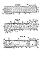
- Fig. 1 is a perspective view of one embodiment of the heat-exchanger 20 of the present invention.
- the heat-exchanger 20 has opposed broad side walls 22, and top and bottom walls 24 and 26.
- the heat-exchanger has an upper angular extension 28 defining an upper inlet/outlet 30, and a lower angular extension 32 defining a lower inlet/outlet 34 connected internally to the upper inlet/outlet 30.
- the inlet/outlets 30 and 34 and the internal passageways (not visible in Fig. 1) interconnecting them form a first gas flow conduit.
- a second gas flow conduit is formed by inlet/outlets 36 and 38 at the right and left ends of the heat-exchanger, and internal passageways (not visible in Fig. 1) interconnecting them.
- Each of the various inlet/outlets 30, 34, 36 and 38 is capable of being used either as an inlet or outlet for the flow of gases through the heat-exchanger.
- the two gas flow conduits are constructed to be parallel to one another over a substantial portion of their lengths so as to produce counterflow heat exchange when the gases flow in opposite directions.
- the heat-exchanger 20 is made of a plurality of vertical panels or sheets 40, 42 interleaved with and secured to one another preferably in alternating sequence.
- Fig. 2 is a side elevation view of one of the panels 40
- Fig. 3 is a similar view of one of the panels 42.
- the panels 40 and 42 are cut to have relatively long, straight parallel upper and lower edges with upper and lower angular extensions 44 and 46, and 63 and 65, respectively.
- the extensions are of the same size and shape so as to form the extensions 28 and 32 (Fig. 1) when the panels are assembled together.
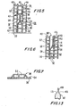
- both panels 40 and 42 are made of "sign-board” material, whose construction is shown in cross-section in Fig. 5.
- each panel 40 has relatively thin opposed outside walls 54 and 56 with broad surfaces, and elongated integral tubes 53 of rectangular or square cross-section formed between two walls 54 and 56.
- the panels are believed to be extruded from a thermoplastic material such as polypropylene, polyethylene or polystyrene.
- Sign-board material typically is used as relatively lightweight, strong and inexpensive material for making signs or displays.
- each panel 42 is substantially the same as the structure of panel 40, and consists of outside walls 45 and 47 and tubes 43.
- the panels may be thicker than panels 40, and the tubes 43 larger in cross-sectional area than the tubes 52, so as to facilitate the flow conduit formation process.
- the broad surfaces 45 and 47 of each panel 42 are indented in selected areas to form a pair of gas flow cavities 66.
- the indentations are made by means of dies such as the dies 136 and 138 shown in Fig. 11.
- the dies preferably are heated in order to permanently deform the panel material.
- gas flow passageways or conduits 67 and 69 are formed. Heat is transferred between the gas in conduits 67 and 69 and a single-thickness wall 56 of each adjacent panel 40. This is an advantage over prior heat exchangers in which heat is transferred through multiple wall thicknesses.
- the indentations compress the internal walls of the tubes together to form a two-ply wall 84 in the center of the panel 42, with ribs 86 extending outwardly at the locations of the compressed internal walls.
- vanes 76 are formed in the gas flow cavities 66 by the provision of cavities in the dies 13 and 138 (Fig. 11), which has the effect of leaving the panel material uncompressed and projecting outwardly from the two-ply wall 84.
- the vanes 76 are arranged to serve as baffles to ensure the turbulent flow of gas along sinuous paths 80 through the conduits 67 and 69, thus increasing the heat transfer efficiency of the heat-exchanger.
- Optional guide and support vanes 82 and 83 are formed by the same process as the vanes 76 to divide the inlet section of each cavity 66 into the passageways 72 and 74.
- the vanes 82 and 83 help to direct the flow of air through the conduits 67 and 69 first horizontally, from right to left, as shown in Fig. 3, and then outwardly and downwardly through the outlet passageways 72 and 74.
- vanes 72, 74, 76, 82 and 83 also help to support the adjacent portions of panels 40 to maintain a constant spacing of the panels from one another over the relatively broad span of the inlet and outlet openings.
- FIG. 4 An alternative panel construction 88 is shown in Fig. 4.
- Panel 88 is an alternative to the panel 40 for conducting the gas flow from one end 38 (Fig. 1) to the opposite end 36.
- Panel 88 has one or more indentations 94 with vanes 96, 102 and 104 formed by the same process as the vanes 76.
- the dashed lines 97 indicate the locations of rows of added vanes 96, which are not shown in Fig. 4 for the sake of simplification of the drawings.
- the vanes 102 and 104 are provided in order to support the adjacent panels in the heat-exchanger, and to guide gases into and out of the flow passages of the heat-exchanger.
- Fig. 7 shows the cross-sectional shape of one of the vanes 96.
- the advantage of the panel 88 over the panel 40 is that the gas flow through the conduits is turbulent, thus further increasing the heat-transfer efficiency of the heat-exchanger.
- the gas flow cavities in the panels be formed by indenting both broad side walls of the panels to form a central two-ply web 84 as shown in Fig. 5, alternatively, the panels can be indented from only one side to form the gas flow cavity 94.
- Fig. 6 is a cross-sectional view taken along line 6-6 of Fig. 4 showing this alternative construction.
- the panel which is indented has broad side walls 54 and 56 with tubes 52.
- the panel is heat-compressed to form a gas flow passageway in the area 112, and a two-ply wall 113 with ridges 114 at the locations of the compressed inner walls.
- Heat is transferred between the gas in the conduit 112 and that flowing in the tubes 52 of the adjacent panels 40. Although heat is transferred through only one wall thickness in the case of the wall 56, heat must flow through the two-ply wall 113 and wall 54, when being transferred between conduit 112 and the right-hand panel conduits 52 shown in Fig. 6.
- the heat transfer reduction can be minimized by reducing the internal and external wall thickness of the panels 88, and by removing substantial sections of the two-ply wall 113 at many locations (e.g. 115 - see Fig. 4), in the panel shaping process.
- the panels 40 utilize the tubes 52, which extend the whole length of the panel, as gas flow conduits.
- the panels 42 and 88 do not use the tubes to conduct gas. Instead, the panels are merely used as low-cost thermoplastic sheet material from which to form gas flow conduits. It is possible to use other sheet materials instead for the starting sheets for forming the panels 42 and 88.
- sheets of expanded thermoplastic materials such as polypropylene, polyethylene or polystyrene can be used instead of the "sign-board" material.
- sheet materials are widely used as insulating panels in home construction, as flotation materials for floating docks, etc.
- Fig. 13 is a broken-away cross-section of a panel of expanded thermoplastic material 117 compressed at 119 to form gas flow cavities 121 and 123. This construction can be easier and less expensive to make than that using sign-board as the starting material for all panels.
- thermo-plastic sheets still hot after being formed, can be stamped or molded rapidly to provide the desired gas flow cavities without the heating of dies.
- Some materials may be subject to permanent deformation by the use of cool dies alone. It also is within the scope of the invention to use those materials as alternatives.
- the next step in making the heat-exchanger 20 after cutting and forming the panels is to adhere the panels together, with broad surfaces contacting one another, in alternating sequence. That is, for example, a panel 40 forms one side wall 22 of the heat-exchanger, and a panel 42 is secured to it. The next panel is another panel 40, the next is another panel 42, etc. The other side wall 22 of the heat-exchanger would be another panel 40.
- the panels are adhered to one another with silicone adhesive, or by use of the process partially illustrated in Fig. 10.
- flaming jets 124 are pointed downwardly from burner nozzles 126 fed with fuel (e.g., natural gas) from a manifold 132.
- fuel e.g., natural gas
- the flames are played onto the upper surface of one of the panels 40 while the panel is moved past the flames in the direction 134 at a controlled speed so as to "singe" the upper surface 56 of the panel 40. This slightly melts or softens the upper surface of the panel.
- the next panel is placed on top of the first panel, either with or without singeing the surface which is to make contact with the first panel, and the panels are pressed together and allowed to cool to cause them to adhere.
- This process then is repeated for each subsequent panel added to the stack until a pre-determined number of layers has been formed.
- the panels can be held together by many other methods and structures.
- metal clamps can be formed out of metal angles and cross rods (not shown) clamping the panels together.
- Another assembly method which is believed to be feasible, under some circumstances, is to simply clamp the panels together temporarily until the edges of the panels are fused together, in the manner to be described below, and then removing the clamps, with the fused edges being sufficient to hold the panels together.
- Fig. 8 shows the preferred method of forming the top and bottom walls 24 and 26.
- the panels then are turned over to use the same process to form the opposite wall.
- a second heated roller spaced vertically from the roller 188 can be used simultaneously to form the top and bottom walls in one pass of the panels through the heated roller mechanism.
- heated rollers such as ultrasonically-heated rollers or rollers heated with electrical resistance heating.
- a flame array like that shown in perspective view in Fig. 12 is used.
- the array is shown in Fig. 9 in a side elevation view to show the features of each flame 124.
- the flame 124 is a jet of burning gas moving downwardly in the direction of the arrows 128.
- the position and thrust of the jet are adjusted so that just the bottom portion of the flame touches the upper edges 122 of the panel assembly as the assembly is moved past the flame array in the direction of the arrow.
- the dwell time of the flames on the panel edges is controlled empirically to limit the melting of the panel end to just enough to fuse the adjacent panel ends together without significantly closing the gas passageways in the panels.
- the fused top and bottom walls 24 and 26, and the fused edges of the panels at the inlet/outlet locations produce a strong heat-exchanger structure which is capable of supporting itself without a separate housing, thus saving substantial costs for sheet metal and sheet metal fabrication as compared with comparable prior heat-exchangers.
- the heat-exchanger 20 is weather-resistant, highly corrosion-resistant, relatively to keep clean, and efficient, as well as being relatively economical to make.
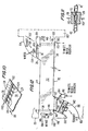
- Fig. 12 is a partially-schematic side-elevation view of a ventilation system utilizing the heat-exchanger 20 of the invention to ventilate a building or other conditioned space 160.
- a first fan 144 is positioned at the left inlet end 38 of the heat-exchanger to push outside air (“OSA”) through the heat-exchanger and out of the outlet 36 and into the conditioned space 160.
- OSA outside air
- the outside air flows as indicated by the arrows 146 and 148 through an opening 149 in the wall 151 of a building and a fitting 147 secured to the left end of the heat-exchanger, and out through another fitting 153 secured to the right end of the heat-exchanger.
- Curved fittings 154 and 156 fit over the angular extensions 28 and 32 of the heat-exchanger.
- outlet fitting 156 Mounted inside of outlet fitting 156 is a duct fan 142 which acts as a suction fan to pull exhaust air thorough inlet duct 154 and the heat-exchanger and expel the air through an exhaust outlet 155.
- duct fan 142 acts as a suction fan to pull exhaust air thorough inlet duct 154 and the heat-exchanger and expel the air through an exhaust outlet 155.
- a motorized damper 152 At the exhaust inlet end of the heat-exchanger is a motorized damper 152, a water spray nozzle 150, and a porous mat 158 onto which the spray nozzle 150 sprays water to create evaporative cooling of the exhaust air, when needed.
- either the fiberglass mat 158 or the damper 152, or a combination of both is used to create a restriction to the inflow of exhaust air into the heat-exchanger.
- damper 152 is preferred so as to minimize the restriction caused by the mat 158, especially when evaporative cooling is not required.
- the exhaust fan 142 preferably is a centrifugal duct fan which occupies the full width of the duct 156 and is capable of creating a substantial pressure drop.
- the combination of this suction fan with the flow restriction creates a significant pressure drop in the exhaust air entering the heat-exchanger. This is believed to significantly increase the evaporation of water and, hence, the evaporative cooling of the exhaust air.
- This ventilating system provides resistance to the leakage of exhaust air into the incoming fresh air through any leaks which may exist in the heat-exchanger. This is because the exhaust air in the heat-exchanger is at a lower pressure than the outside air, and any leaks would allow flow from the higher pressure conduits to the low pressure conduits, but not in the opposite direction.
- the heat-exchanger 20 is mounted with the right end slightly higher than the left so that the body of the heat-exchanger forms an angle ⁇ of around 5 degrees with horizontal. This promotes drainage of condensate and excess water from the evaporative cooling system towards the left end 38
- a gutter 162 is provided in the duct 156 to catch the water draining from the exhaust passageways of the heat-exchanger.
- a float valve 164 is provided. It closes the drain system until the water level in the tank of the valve 164 reaches a level sufficient to overcome the negative pressure of the fan 142. This prevents the drain from leaking air into the fitting 156 and reducing the effectiveness of the fan.
- a similar gutter 166 and drain 170 are provided at the right end of the heat-exchanger, if needed.
- a similar gutter and drain can be provided at the left end of the heat-exchanger, if needed.
- the system shown in Fig. 12 preferably also has suitable control means for controlling the operation of the ventilator in heating, cooling and intermediate cooling modes, as described in my above-identified patent and pending patent application. Louvers, bypass ducts, de-icing means, etc., described there all can be used in the system of Fig. 12, as needed or desired.
Abstract
Description
- This invention relates to ventilating systems and methods using heat-exchangers for energy recovery, and to heat exchangers, especially exchangers suitable for use in such systems, and to methods for fabricating heat exchangers.
- This patent application is a continuation-in-part of patent application Serial No. 09/188,729, filed November 9,1998, new U.S. Patent No. 6,176,305, and Serial No. 09/579,739 filed May 26, 2000. The disclosures of those patent applications are hereby incorporated herein by reference.
- The ventilating systems of the above-identified patent applications represent significant improvements over prior ventilating systems. Nonetheless, further improvements are desirable, and it is an object of this invention to provide them.
- One embodiment of the ventilating system of the above patent applications uses evaporative cooling to cool exhaust air exiting a building or other conditioned space. Although the evaporative cooling feature significantly enhances the efficiency of cooling the conditioned space, even greater cooling is highly desirable, as long as power and equipment costs are not increased excessively.
- Prior energy-recovery ventilating systems and others using isolating heat-exchangers, that is, heat-exchangers which isolate the gas flows from one another, often suffer from the effects of leakage in the heat exchanger. This leakage causes undesired mixing of the two gases from one another. In a ventilating system, this can mean that the stale exhaust air mixes with the incoming fresh air, and leads to reduced air quality and even contamination of the incoming fresh air.
- A third problem occurs with the preferred heat exchanger used in my above-described prior system. That heat-exchanger is made out of extruded thermoplastic panels composed of side-by-side plastic tubes. The heat-exchanger is admirably suited to use with evaporative cooling equipment because mold and other such nemeses do not adhere strongly to the heat-exchanger surfaces, and can be removed relatively easily. Also, the heat-exchanger is relatively inexpensive to build and lasts much longer than most metallic heat-exchangers.
- A problem with such heat-exchangers is that most are relatively less efficient in the transfer of heat than they could be.
- Another problem is that such prior heat-exchangers usually require relatively expensive housings, often made of sheet-metal.
- A further problem is that such prior heat-exchangers usually are assembled using hand labor, and thus are more time-consuming and expensive to make than they need be.
- In accordance with the present invention, the foregoing problems are solved or alleviated by the provisions of a ventilating system and method which includes evaporative cooling of the exhaust air before it enters a heat exchanger to cool incoming fresh outside air. A suction fan pulls exhaust air through the heat exchanger and, in combination with a flow restrictor, reduces the pressure on the exhaust air and augments the evaporative cooling.
- Preferably, another fan is used to push outside air through the heat-exchanger and into the conditioned space.
- The use of a pusher fan to force outside air through the heat exchanger ensures that any leakage in the heat-exchanger results in outside air entering exhaust air and minimizing the chances of contamination by leaking exhaust air into the incoming fresh air.
- The heat exchanger is made economically by die-forming cavities in relatively thick thermo-plastic sheets, interleaving them with other thermo-plastic sheets having separate gas flow conduit structures, and securing the sheets together. Preferably, the heat-exchanger is an opposed-flow heat-exchanger giving improved heat-transfer efficiency.
- In one embodiment, some or all of the sheets are panels of parallel, side-by-side thermoplastic tubes.
- In one specific embodiment, the tubes in every other sheet are left intact and serve as conduits for one gas, such as outside air, while the other sheets are indented to form separate conduits for another gas, such as exhaust air.
- In another specific embodiment, the sheets indented to form gas flow passages are panels made of expanded thermoplastic materials.
- In a further specific embodiment, all of the panels have gas flow conduits formed by indenting the sheets.
- Preferably, the outside edges of the sheets stacked together are hot-compressed, with a heated roller, e.g. to melt the plastic of the edges to form a relatively thick outer wall which is strong and helps avoid the cost of a metal housing for the heat-exchanger. Flame singeing is used to fuse the ends of gas flow conduits together.
- The sheets are secured together, broad-face to broad-face, either with silicone adhesive, or preferably, by heat-singeing at least one broad surface of one of the sheets to make it tacky before another sheet is pressed against the tacky surface to adhere the sheets together.
- Vanes are die-formed in some of the gas flow passages to increase turbulence and heat-transfer efficiency.
- Die forming can be done with heated or cool dies, depending upon the type of panel being used and its condition -- whether hot and soft or cool and hard, for example.
- The foregoing and other objects and advantages of the invention will be set forth in or apparent from the following description and drawings.
- Fig. 1 is a perspective view of a heat-exchanger constructed in accordance with the present invention;
- Figs. 2, 3 and 4 are side-elevation views of sheets or panels used to make the heat-exchanger of Fig. 1;
- Figs. 5, 6, and 7 are cross-sectional views, partially broken-away, showing plural adjacent panels of heat-exchangers using the panels of Figs. 2, 3 and 4, and are taken at the locations indicated by the lines 5-5 , 6-6 and 7-7, respectively;
- Figs. 8, 9, 10 and 11 are perspective and cross-sectional partially-schematic views illustrating equipment and steps used in the manufacture of the heat-exchanger of Fig. 1;
- Fig. 12 is an elevation view, partially schematic, showing a ventilating system of the present invention; and
- Fig. 13 is a cross-sectional view of a portion of an alternative panel used in the invention.
-
- Fig. 1 is a perspective view of one embodiment of the heat-
exchanger 20 of the present invention. - The heat-
exchanger 20 has opposedbroad side walls 22, and top andbottom walls - The heat-exchanger has an upper
angular extension 28 defining an upper inlet/outlet 30, and a lowerangular extension 32 defining a lower inlet/outlet 34 connected internally to the upper inlet/outlet 30. The inlet/outlets - A second gas flow conduit is formed by inlet/
outlets - Each of the various inlet/
outlets - As it will be explained in detail below, the two gas flow conduits are constructed to be parallel to one another over a substantial portion of their lengths so as to produce counterflow heat exchange when the gases flow in opposite directions.
- The heat-
exchanger 20 is made of a plurality of vertical panels orsheets - Fig. 2 is a side elevation view of one of the
panels 40, and Fig. 3 is a similar view of one of thepanels 42. - The
panels angular extensions extensions 28 and 32 (Fig. 1) when the panels are assembled together. - Preferably, both
panels - As it is shown in Fig. 5, each
panel 40 has relatively thin opposed outsidewalls walls - The structure of each
panel 42 is substantially the same as the structure ofpanel 40, and consists ofoutside walls tubes 43. The panels may be thicker thanpanels 40, and thetubes 43 larger in cross-sectional area than thetubes 52, so as to facilitate the flow conduit formation process. - As it is shown in Figs. 3 and 5, the
broad surfaces panel 42 are indented in selected areas to form a pair ofgas flow cavities 66. Preferably, the indentations are made by means of dies such as thedies 136 and 138 shown in Fig. 11. The dies preferably are heated in order to permanently deform the panel material. - When the
panels conduits conduits thickness wall 56 of eachadjacent panel 40. This is an advantage over prior heat exchangers in which heat is transferred through multiple wall thicknesses. - As it is shown in Fig. 5, the indentations compress the internal walls of the tubes together to form a two-
ply wall 84 in the center of thepanel 42, withribs 86 extending outwardly at the locations of the compressed internal walls. - Preferably, vanes 76 (see Fig. 3) are formed in the
gas flow cavities 66 by the provision of cavities in the dies 13 and 138 (Fig. 11), which has the effect of leaving the panel material uncompressed and projecting outwardly from the two-ply wall 84. Thevanes 76 are arranged to serve as baffles to ensure the turbulent flow of gas alongsinuous paths 80 through theconduits - Optional guide and
support vanes 82 and 83 (Fig. 3) are formed by the same process as thevanes 76 to divide the inlet section of eachcavity 66 into thepassageways vanes 82 and 83 help to direct the flow of air through theconduits - The
vanes panels 40 to maintain a constant spacing of the panels from one another over the relatively broad span of the inlet and outlet openings. - An
alternative panel construction 88 is shown in Fig. 4. -
Panel 88 is an alternative to thepanel 40 for conducting the gas flow from one end 38 (Fig. 1) to theopposite end 36. -
Panel 88 has one ormore indentations 94 withvanes vanes 76. The dashed lines 97 indicate the locations of rows of addedvanes 96, which are not shown in Fig. 4 for the sake of simplification of the drawings. - The
vanes - Fig. 7 shows the cross-sectional shape of one of the
vanes 96. - The advantage of the
panel 88 over thepanel 40 is that the gas flow through the conduits is turbulent, thus further increasing the heat-transfer efficiency of the heat-exchanger. - Although it is preferred that the gas flow cavities in the panels be formed by indenting both broad side walls of the panels to form a central two-
ply web 84 as shown in Fig. 5, alternatively, the panels can be indented from only one side to form thegas flow cavity 94. - Fig. 6 is a cross-sectional view taken along line 6-6 of Fig. 4 showing this alternative construction. The panel which is indented has
broad side walls tubes 52. The panel is heat-compressed to form a gas flow passageway in thearea 112, and a two-ply wall 113 withridges 114 at the locations of the compressed inner walls. - Heat is transferred between the gas in the
conduit 112 and that flowing in thetubes 52 of theadjacent panels 40. Although heat is transferred through only one wall thickness in the case of thewall 56, heat must flow through the two-ply wall 113 andwall 54, when being transferred betweenconduit 112 and the right-hand panel conduits 52 shown in Fig. 6. - This potential reduction in heat transfer efficiency, as compared with the Fig. 5 embodiment, can be acceptable as a compromise to avoid having to make two sets of heat-forming dies or heat-forming both sides of the panels in separate steps using the same dies, if the extra die cost is avoided by using the same dies to form both sides of one panel.
- The heat transfer reduction can be minimized by reducing the internal and external wall thickness of the
panels 88, and by removing substantial sections of the two-ply wall 113 at many locations (e.g. 115 - see Fig. 4), in the panel shaping process. - The
panels 40 utilize thetubes 52, which extend the whole length of the panel, as gas flow conduits. However, thepanels panels - For example, it is believed that sheets of expanded thermoplastic materials, such as polypropylene, polyethylene or polystyrene can be used instead of the "sign-board" material. Such sheet materials are widely used as insulating panels in home construction, as flotation materials for floating docks, etc.
- Fig. 13 is a broken-away cross-section of a panel of expanded
thermoplastic material 117 compressed at 119 to formgas flow cavities - Similarly, other compressible and/or heat-formable sheets may be advantageous to use as starting materials. For example, expanded or solid thermo-plastic sheets, still hot after being formed, can be stamped or molded rapidly to provide the desired gas flow cavities without the heating of dies. Some materials may be subject to permanent deformation by the use of cool dies alone. It also is within the scope of the invention to use those materials as alternatives.
- The next step in making the heat-
exchanger 20 after cutting and forming the panels is to adhere the panels together, with broad surfaces contacting one another, in alternating sequence. That is, for example, apanel 40 forms oneside wall 22 of the heat-exchanger, and apanel 42 is secured to it. The next panel is anotherpanel 40, the next is anotherpanel 42, etc. Theother side wall 22 of the heat-exchanger would be anotherpanel 40. - The panels are adhered to one another with silicone adhesive, or by use of the process partially illustrated in Fig. 10.
- Referring to Fig. 10, several
flaming jets 124 are pointed downwardly fromburner nozzles 126 fed with fuel (e.g., natural gas) from amanifold 132. The flames are played onto the upper surface of one of thepanels 40 while the panel is moved past the flames in thedirection 134 at a controlled speed so as to "singe" theupper surface 56 of thepanel 40. This slightly melts or softens the upper surface of the panel. Then, the next panel is placed on top of the first panel, either with or without singeing the surface which is to make contact with the first panel, and the panels are pressed together and allowed to cool to cause them to adhere. - This process then is repeated for each subsequent panel added to the stack until a pre-determined number of layers has been formed.
- The panels can be held together by many other methods and structures.
- For example, metal clamps can be formed out of metal angles and cross rods (not shown) clamping the panels together.
- Another assembly method which is believed to be feasible, under some circumstances, is to simply clamp the panels together temporarily until the edges of the panels are fused together, in the manner to be described below, and then removing the clamps, with the fused edges being sufficient to hold the panels together.
- Fig. 8 shows the preferred method of forming the top and
bottom walls - When the panels are stacked together, the edges are aligned with one another to form straight surfaces. Then, a
heated roller 118 is pressed firmly against theupper edges 116 of the panels while the panels are moved as indicated by the arrow 120. This progressively compresses and melts the upper edges of the panels, and the melted plastic is rolled by the roller to form a solid wall of melted plastic. - The panels then are turned over to use the same process to form the opposite wall.
- Alternatively, a second heated roller (not shown), spaced vertically from the roller 188 can be used simultaneously to form the top and bottom walls in one pass of the panels through the heated roller mechanism.
- Many types of heated rollers can be used, such as ultrasonically-heated rollers or rollers heated with electrical resistance heating.
- The edges of the panels at the four inlet/
outlets - A flame array like that shown in perspective view in Fig. 12 is used. The array is shown in Fig. 9 in a side elevation view to show the features of each
flame 124. - The
flame 124 is a jet of burning gas moving downwardly in the direction of thearrows 128. The position and thrust of the jet are adjusted so that just the bottom portion of the flame touches the upper edges 122 of the panel assembly as the assembly is moved past the flame array in the direction of the arrow. - The dwell time of the flames on the panel edges is controlled empirically to limit the melting of the panel end to just enough to fuse the adjacent panel ends together without significantly closing the gas passageways in the panels.
- Other means can be used to fuse the ends and edges of the panels together, such as heated rollers and like devices.
- The fused top and
bottom walls - The heat-
exchanger 20 is weather-resistant, highly corrosion-resistant, relatively to keep clean, and efficient, as well as being relatively economical to make. - Fig. 12 is a partially-schematic side-elevation view of a ventilation system utilizing the heat-
exchanger 20 of the invention to ventilate a building or otherconditioned space 160. - As in my patent 6,176,305, a
first fan 144 is positioned at theleft inlet end 38 of the heat-exchanger to push outside air ("OSA") through the heat-exchanger and out of theoutlet 36 and into the conditionedspace 160. - The outside air flows as indicated by the
arrows opening 149 in thewall 151 of a building and a fitting 147 secured to the left end of the heat-exchanger, and out through another fitting 153 secured to the right end of the heat-exchanger. -
Curved fittings angular extensions - Mounted inside of outlet fitting 156 is a
duct fan 142 which acts as a suction fan to pull exhaust airthorough inlet duct 154 and the heat-exchanger and expel the air through anexhaust outlet 155. - At the exhaust inlet end of the heat-exchanger is a motorized damper 152, a
water spray nozzle 150, and aporous mat 158 onto which thespray nozzle 150 sprays water to create evaporative cooling of the exhaust air, when needed. - In accordance with the present invention, either the
fiberglass mat 158 or the damper 152, or a combination of both is used to create a restriction to the inflow of exhaust air into the heat-exchanger. - Use of the damper 152 is preferred so as to minimize the restriction caused by the
mat 158, especially when evaporative cooling is not required. - The
exhaust fan 142 preferably is a centrifugal duct fan which occupies the full width of theduct 156 and is capable of creating a substantial pressure drop. The combination of this suction fan with the flow restriction creates a significant pressure drop in the exhaust air entering the heat-exchanger. This is believed to significantly increase the evaporation of water and, hence, the evaporative cooling of the exhaust air. - Another advantage of this ventilating system is that it provides resistance to the leakage of exhaust air into the incoming fresh air through any leaks which may exist in the heat-exchanger. This is because the exhaust air in the heat-exchanger is at a lower pressure than the outside air, and any leaks would allow flow from the higher pressure conduits to the low pressure conduits, but not in the opposite direction.
- Thus, stale air is not allowed to mix to any significant degree with the fresh air coming into the conditioned space. Although this is highly desirable in any residential or commercial building, it is especially advantageous in hospitals or doctor's offices where it is important to prevent such mixing in order to prevent the spreading of pathogens.
- Preferably, the heat-
exchanger 20 is mounted with the right end slightly higher than the left so that the body of the heat-exchanger forms an angle of around 5 degrees with horizontal. This promotes drainage of condensate and excess water from the evaporative cooling system towards theleft end 38 - A
gutter 162 is provided in theduct 156 to catch the water draining from the exhaust passageways of the heat-exchanger. The water gathered there flows through aline 168 to an optional waste water recovery facility (not shown) which returns the water for re-use in evaporative cooling, or elsewhere. - A
float valve 164 is provided. It closes the drain system until the water level in the tank of thevalve 164 reaches a level sufficient to overcome the negative pressure of thefan 142. This prevents the drain from leaking air into the fitting 156 and reducing the effectiveness of the fan. - A similar gutter 166 and drain 170 are provided at the right end of the heat-exchanger, if needed. A similar gutter and drain can be provided at the left end of the heat-exchanger, if needed.
- The system shown in Fig. 12 preferably also has suitable control means for controlling the operation of the ventilator in heating, cooling and intermediate cooling modes, as described in my above-identified patent and pending patent application. Louvers, bypass ducts, de-icing means, etc., described there all can be used in the system of Fig. 12, as needed or desired.
- The above description of the invention is intended to be illustrative and not limiting. Various changes or modifications in the embodiments described may occur to those skilled in the art. These can be made without departing from the spirit or scope of the invention.
Claims (10)
- A method of ventilating an enclosed space using an air handling system including a heat exchanger for conducting exhaust air from said enclosed space and outside air into said enclosed space and selectively exchanging heat between said exhaust air and said outside air, a first fan to move said exhaust air through said heat exchanger, a second fan to move said outside air through said heat exchanger, said first fan being located downstream from said heat exchanger in the flow path of said exhaust air for pulling said exhaust air out of said heat exchanger, the steps of:(a) evporatively cooling said exhaust air at a cooling location upstream of said heat exchanger in said flow path of said exhaust air, and(b) creating a substantial air pressure drop between said first fan and said cooling location to augment said evaporative cooling.
- A method as in Claim 1 in which said creating step includes providing a restriction to the flow of said exhaust air through said heat exchanger.
- A ventilator for ventilating an enclosed space, said ventilator including:(a) a heat exchanger for conducting exhaust air from said enclosed space and outside air into said enclosed space, and selectively exchanging heat between said outside air and said exhaust air,(b) a first fan to move said exhaust air through said heat exchanger in a first direction, and(c) a second fan to move said outside air through said heat exchanger in a direction generally opposite to said first direction,(d) said first fan being a suction fan located downstream from said heat exchanger and being oriented to pull air through said heat exchanger,(e) a flow restrictor positioned to restrict flow or exhaust air through said heat exchanger and produce a substantial pressure reduction in exhaust air flowing through said heat exchanger, and(f) an evaporative cooling device for evaporatively cooling said exhaust air flowing through said heat exchanger.
- A ventilator as in Claim 3 in which said flow restrictor is selected from the group consisting of an adjustable damper and a water evaporation mat positioned to at least partially restrict the flow of said exhaust air into said heat exchanger, said mat being part of said evaporative cooling device.
- A ventilator for ventilating an enclosed space, said ventilator including:(a) a heat exchanger for conducting exhaust air from said enclosed space and outside air into said enclosed space, and selectively exchanging heat between said outside air and said exhaust air,(b) a first fan to move said exhaust air through said heat exchanger in one direction, and(c) a second fan to move said outside air through said heat exchanger in a direction transverse to said first direction,(d) said first fan being a suction fan located downstream from said heat exchanger and being oriented to pull air through said heat exchanger, said second fan being positioned upstream from said heat exchanger and being oriented to push said outside air through said heat exchanger.
- A method of making a plastic heat exchanger for transferring heat from one gas to another while maintaining a barrier between them to isolate one gas from the other,
providing a plurality of panels of plastic material, each having a substantial thickness, and two opposed broad surfaces,
pressure-forming at least one broad surface of selected ones of said panels to form at least one gas passage cavity in each,
providing the others of said panels with elongated gas flow passages,
interleaving said selected sheets with said others of said panels in a predetermined sequence, and
securing said panels together with broad surfaces thereof contacting one another,
said gas passage cavities, together with surfaces of adjacent panels, forming conduits for one of said gases, and said elongated gas flow passages forming conduits for the other of said gases. - A method as in Claim 6 in which said panels are made of thermoplastic material, and including the step of heating the broad surface of at least one of said panels to soften the plastic material on said broad surface, and pressing another of said panels against said surface to secure said sheets together.
- A method as in Claim 6 in which said panels are made of thermoplastic material, and including the step of heat-rolling the edges of said panels after assembly to melt plastic material to form a thick plastic wall for the assembly.
- A heat exchanger comprising, in combination,
a plurality of panels of thermoplastic material, each of said panels having two opposed broad surfaces and at lest one edge, each of said broad surfaces having a greater surface area than said edge,
selected ones of said panels having at least one indentation in at least one of said broad surfaces, said indentation forming a gas flow passage cavity,
other of said panels each having at least one gas flow conduit structure forming at least one gas flow conduit,
said selected ones of said panels being interleaved with said others of said panels in a predetermined sequence,
said panels being assembled with said broad surfaces of said sheets joined together so that said gas flow cavity in each of said selected sheets forms a gas flow passageway with one of said broad surfaces of an adjoining one of said other panels. - A heat-exchanger as in Claim 9 in which said gas flow conduit structure in each of said other panels is selected from the group consisting of a plurality of side-by-side thermoplastic tubes and at least one indentation forming a gas flow cavity in at least one of said broad surfaces.
Applications Claiming Priority (2)
| Application Number | Priority Date | Filing Date | Title |
|---|---|---|---|
| US829772 | 2001-04-10 | ||
| US09/829,772 US6983788B2 (en) | 1998-11-09 | 2001-04-10 | Ventilating system, heat exchanger and methods |
Publications (2)
| Publication Number | Publication Date |
|---|---|
| EP1249669A2 true EP1249669A2 (en) | 2002-10-16 |
| EP1249669A3 EP1249669A3 (en) | 2003-08-13 |
Family
ID=25255515
Family Applications (1)
| Application Number | Title | Priority Date | Filing Date |
|---|---|---|---|
| EP02007370A Withdrawn EP1249669A3 (en) | 2001-04-10 | 2002-04-08 | Ventilating system, heat exchanger, method of ventilating an enclosed space and method of making a plastic heat exchanger |
Country Status (3)
| Country | Link |
|---|---|
| US (5) | US6983788B2 (en) |
| EP (1) | EP1249669A3 (en) |
| CA (1) | CA2380138C (en) |
Cited By (6)
| Publication number | Priority date | Publication date | Assignee | Title |
|---|---|---|---|---|
| EP1691142A2 (en) * | 2005-01-12 | 2006-08-16 | Schütz GmbH & Co. KGaA | Air-Air heat exchanger for room ventilation systems |
| EP1862754A3 (en) * | 2006-06-01 | 2008-07-30 | TRIPLEX Kunststoffe GmbH | Heat exchange device and method for its manufacture |
| LT5511B (en) | 2007-08-21 | 2008-08-25 | Edvardas RAČKAUSKAS | Heat exchanger |
| WO2010076574A3 (en) * | 2009-01-02 | 2011-03-17 | Envirovent Limited | Heat exchanger module |
| EP2375181A1 (en) * | 2010-04-12 | 2011-10-12 | Università Degli Studi Di Torino | Ventilator with a counterflow heat exchanger |
| EP2431699A1 (en) * | 2010-09-20 | 2012-03-21 | Thermal Corp. | Cooling apparatus |
Families Citing this family (48)
| Publication number | Priority date | Publication date | Assignee | Title |
|---|---|---|---|---|
| DE10302708A1 (en) * | 2003-01-23 | 2004-07-29 | Behr Gmbh & Co. Kg | Device for exchanging heat used especially for cooling combustion air in IC engines of vehicles has flow units arranged in a two-part profiled housing |
| EP1610883B1 (en) * | 2003-04-01 | 2014-08-20 | Ebara Corporation | Method for treating an exhaust gas |
| CH697104A5 (en) * | 2004-01-30 | 2008-04-30 | Polybloc Ag | A method of cooling a supply air flow for a room. |
| US20050189097A1 (en) * | 2004-03-01 | 2005-09-01 | The Boeing Company | Formed sheet heat exchanger |
| US7624788B2 (en) * | 2004-04-22 | 2009-12-01 | State Of Oregon Acting By And Through The State Board Of Higher Education On Behalf Of The University Of Oregon | Heat exchanger |
| JP4527557B2 (en) * | 2005-01-26 | 2010-08-18 | 株式会社ティラド | Heat exchanger |
| US20060260790A1 (en) * | 2005-05-18 | 2006-11-23 | Mark Theno | Heat exchanger core |
| CN101541522B (en) * | 2006-08-28 | 2012-07-18 | 丹塞姆空气调节有限公司 | Method for manufacturing a heat exchanger |
| US9920939B2 (en) * | 2007-01-22 | 2018-03-20 | Klas C. Haglid | Dehumidifer/cooler and method |
| US8162042B2 (en) * | 2007-01-22 | 2012-04-24 | Building Performance Equipment, Inc. | Energy recovery ventilator with condensate feedback |
| US9605905B2 (en) * | 2007-01-22 | 2017-03-28 | Klas C. Haglid | Air-to-air counter-flow heat exchanger |
| FR2913107B1 (en) * | 2007-02-23 | 2009-05-08 | Pierre Vironneau | METHOD FOR PRODUCING A THERMAL EXCHANGER AND THERMAL EXCHANGER OBTAINED ACCORDING TO THIS METHOD |
| US8141623B2 (en) * | 2007-05-01 | 2012-03-27 | Blecker Joseph G | Automatic switching two pipe hydronic system |
| JP2010048536A (en) * | 2008-08-25 | 2010-03-04 | Denso Corp | Heat exchanger |
| ITUD20080196A1 (en) * | 2008-09-12 | 2010-03-13 | Thermics Srl | COMPACT THERMAL EXCHANGER WITH HIGH SURFACE OF HEAT EXCHANGE |
| CN102308684B (en) * | 2009-02-09 | 2014-04-30 | 松下电器产业株式会社 | Heat exchanger device and heating element holder using same |
| US8490422B2 (en) * | 2009-04-26 | 2013-07-23 | Alaa Abdulkareem AL WATBAN | Evaporative air cooler with multi stages cooling and or heating with or without cooling coil |
| EP2454548B1 (en) | 2009-07-17 | 2020-04-01 | Lockheed Martin Corporation | Heat exchanger and method for making |
| US9777971B2 (en) | 2009-10-06 | 2017-10-03 | Lockheed Martin Corporation | Modular heat exchanger |
| FR2961891B1 (en) * | 2010-06-23 | 2012-08-03 | Aldes Aeraulique | AERAULIC EXCHANGER WITH ALVEOLE PLATES |
| EP2413045B1 (en) * | 2010-07-30 | 2014-02-26 | Grundfos Management A/S | Heat exchange unit |
| US8875526B1 (en) | 2010-08-09 | 2014-11-04 | Roland H. Isaacson | Temperature and humidity air treatment system |
| RU2459155C2 (en) * | 2010-09-09 | 2012-08-20 | Федеральное Государственное Автономное Образовательное Учреждение Высшего Профессионального Образования "Дальневосточный Федеральный Университет" (Двфу) | Supply-exhaust device |
| US8864017B2 (en) | 2011-10-13 | 2014-10-21 | Orbis Corporation | Plastic corrugated container with improved fold lines and method and apparatus for making same |
| US9279626B2 (en) * | 2012-01-23 | 2016-03-08 | Honeywell International Inc. | Plate-fin heat exchanger with a porous blocker bar |
| US9845960B2 (en) * | 2012-03-07 | 2017-12-19 | Aermist Llc | Evaporative HVAC apparatus |
| WO2013134201A1 (en) | 2012-03-08 | 2013-09-12 | Shell Oil Company | Low profile magnetic orienting protectors |
| SE538217C2 (en) * | 2012-11-07 | 2016-04-05 | Andri Engineering Ab | Heat exchangers and ventilation units including this |
| ES2865176T3 (en) * | 2012-11-08 | 2021-10-15 | Zehnder Group Int Ag | Procedure for manufacturing a plastic plate heat exchanger |
| GB2508424A (en) * | 2012-11-30 | 2014-06-04 | Greenwood Air Man Ltd | Drain arrangement for gas heat recovery unit |
| WO2014190383A1 (en) * | 2013-05-28 | 2014-12-04 | Fusion Hvac Pty Ltd | Packaged heatpump with integrated smokespill |
| US10625916B2 (en) | 2013-12-24 | 2020-04-21 | Orbis Corporation | Plastic corrugated container with soft score line |
| US11643242B2 (en) | 2013-12-24 | 2023-05-09 | Orbis Corporation | Air vent for welded portion in plastic corrugated material, and process for forming welded portion |
| EP3865415A1 (en) * | 2013-12-24 | 2021-08-18 | Orbis Corporation | Manufacturing process of a blank for forming a plastic corrugated container |
| US10829265B2 (en) | 2013-12-24 | 2020-11-10 | Orbis Corporation | Straight consistent body scores on plastic corrugated boxes and a process for making same |
| EP3114422B1 (en) * | 2014-03-07 | 2018-04-11 | Conoco Phillips Company | Heat exchanger system with mono-cyclone inline separator |
| TWI563908B (en) | 2015-01-09 | 2016-12-21 | Young Lighting Technology Inc | Display having fan |
| HUP1500325A2 (en) * | 2015-07-14 | 2017-01-30 | Sciquest Kft | Hvac device for aggregator groups |
| US10573722B2 (en) | 2016-02-17 | 2020-02-25 | General Electric Company | Systems and methods for in-situ doped semiconductor gate electrodes for wide bandgap semiconductor power devices |
| US10212914B1 (en) | 2016-03-09 | 2019-02-26 | Aubrey W. Reynolds | Circulation system and method of circulation |
| AU2017262640B2 (en) | 2016-05-09 | 2022-09-15 | Munters Corporation | Direct evaporative cooling system with precise temperature control |
| RU2643420C1 (en) * | 2016-11-24 | 2018-02-01 | Владимир Михайлович Мартынов | Supply-recirculation plant |
| ES2964921T3 (en) | 2017-02-21 | 2024-04-10 | Orbis Corp | Corrugated plastic boxes with marked fold lines |
| US11072140B2 (en) | 2017-06-20 | 2021-07-27 | Orbis Corporation | Balanced process for extrusion of plastic corrugated sheet and subsequent converting into plastic boxes |
| TWI662236B (en) * | 2018-02-14 | 2019-06-11 | 建準電機工業股份有限公司 | Air exchanger |
| US11209223B2 (en) * | 2019-09-06 | 2021-12-28 | Hamilton Sundstrand Corporation | Heat exchanger vane with partial height airflow modifier |
| CN112781200B (en) * | 2019-11-01 | 2022-11-22 | 广东美的制冷设备有限公司 | Wall-penetrating type air conditioner, control method and device thereof and readable storage medium |
| US11391487B2 (en) | 2020-09-17 | 2022-07-19 | Bradford D Wallace | Air to air cross flow heat and moisture exchanger |
Citations (11)
| Publication number | Priority date | Publication date | Assignee | Title |
|---|---|---|---|---|
| GB1336448A (en) * | 1969-12-12 | 1973-11-07 | Centre Scient Tech Batiment | Heat exchangers |
| DE3011011A1 (en) * | 1979-03-22 | 1980-09-25 | Hitachi Ltd | Plate heat exchange for air separation - having channels through plate for one medium and rectangular grooves on surface which form channels when placed with other plates |
| DE3137296A1 (en) * | 1981-09-18 | 1983-04-14 | Karl-Heinz Ing.(Grad.) 4715 Ascheberg Beckmann | Plate heat exchanger |
| US4461344A (en) * | 1981-04-14 | 1984-07-24 | Greg Allen | Heat exchanger |
| WO1984003756A1 (en) * | 1983-03-21 | 1984-09-27 | Nokia Oy Ab | Air-conditioning system |
| US4901919A (en) * | 1985-09-20 | 1990-02-20 | Wainwright Christopher E | Air conditioning indirect heating and recuperative ventilation system |
| EP0363340A2 (en) * | 1988-10-06 | 1990-04-11 | Sixten Persson | Method and device for conditioning supply air |
| DE3929004A1 (en) * | 1989-09-01 | 1991-03-07 | Behr Gmbh & Co | Heat exchanger for condensn. driers - with hollow quadrangular plastic heat exchange plate having partitioning in hollow space |
| US5119987A (en) * | 1990-03-31 | 1992-06-09 | Kabushiki Kaisha Toshiba | Ventilating apparatus |
| EP1001228A2 (en) * | 1998-11-09 | 2000-05-17 | Building Performance Equipment Inc. | Ventilator system and method |
| DE19958106A1 (en) * | 1999-11-17 | 2001-02-22 | Joma Polytec Kunststofftechnik | Cross flow heat exchanger comprises numerous flat heat exchanger plates arranged in parallel, and a damp air channel. |
Family Cites Families (70)
| Publication number | Priority date | Publication date | Assignee | Title |
|---|---|---|---|---|
| DE204310C (en) * | ||||
| US2247542A (en) | 1941-07-01 | Thermo static air conditioning | ||
| US1662870A (en) * | 1924-10-09 | 1928-03-20 | Stancliffe Engineering Corp | Grooved-plate heat interchanger |
| GB272926A (en) * | 1926-06-19 | 1928-03-15 | Siemens Schuckertwerke Gmbh | Improvements in or relating to air preheaters for furnaces and the like |
| DE540204C (en) * | 1929-11-10 | 1932-11-08 | Hoesch & Soehne Eberhard | Heater for evaporator |
| GB1354502A (en) * | 1970-08-28 | 1974-06-05 | Ici Ltd | Heat exchangers |
| DE2325261A1 (en) | 1973-05-18 | 1974-12-05 | Elizabeth B Gerald | READING SUPPORT COMBINED WITH A PROTECTIVE COVER FOR A BOOK |
| JPS5031464A (en) * | 1973-05-25 | 1975-03-27 | ||
| US3912004A (en) | 1974-05-10 | 1975-10-14 | William J Darm | Heat exchanger apparatus with spacer projections between plates |
| US4069030A (en) * | 1976-08-20 | 1978-01-17 | Air Conditioning Corporation | Energy conservation enthalpy control system and sensor therefor |
| US4293027A (en) | 1977-10-25 | 1981-10-06 | Energetics Systems Corp. | Control system for heating and cooling units |
| US4411310A (en) * | 1978-04-07 | 1983-10-25 | The Boeing Company | Heat exchange apparatus having thin film flexible sheets |
| US4174987A (en) | 1978-04-07 | 1979-11-20 | The Boeing Company | Method of making heat exchange structure |
| DE2965045D1 (en) * | 1978-11-06 | 1983-04-21 | Akzo Nv | Apparatus for the exchange of heat by means of channels having a small diameter, and the use of this apparatus in different heating systems |
| JPS6032800B2 (en) * | 1979-06-01 | 1985-07-30 | 株式会社日立製作所 | Heat exchanger |
| FR2469684A1 (en) * | 1979-11-13 | 1981-05-22 | Thermo Electronique France Sa | Heat exchanger for two fluids - has modular construction of stacked flat plastics sheets with interposed partitions to form passages |
| JPS6011781B2 (en) | 1979-12-04 | 1985-03-28 | 三菱電機株式会社 | Air conditioner control device |
| JPS6049687B2 (en) | 1980-02-27 | 1985-11-05 | 川崎製鉄株式会社 | Tuyere cooling method |
| JPS571731A (en) * | 1980-06-03 | 1982-01-06 | Sekisui Chem Co Ltd | Manufacture of expanded plastic sheet |
| EP0044561A3 (en) * | 1980-07-21 | 1982-07-14 | MüANYAGIPARI KUTATO INTEZET | Heat exchanger, in particular for heat exchange between gaseous fluids |
| DE3030778A1 (en) | 1980-08-14 | 1982-02-18 | Weiss Technik GmbH Umwelt-Klima-Messtechnik, 6301 Reiskirchen | Stale air heat recovery heat exchanger - has stale and external air by=pass valves, operated separately |
| JPS5755338A (en) | 1980-09-18 | 1982-04-02 | Sharp Corp | Ventilating fan with heat exchanger |
| US4475589A (en) * | 1981-01-21 | 1984-10-09 | Tokyo Shibaura Denki Kabushiki Kaisha | Heat exchanger device |
| US4356053A (en) * | 1981-05-11 | 1982-10-26 | Ethyl Corporation | Edge sealing of laminate |
| DE3128684A1 (en) | 1981-07-21 | 1983-02-10 | Metallbau Sevelen AG, Sevelen, St. Gallen | Kit for preferably seasonally adapted and automatic room air-conditioning |
| JPS5843398A (en) * | 1981-09-10 | 1983-03-14 | Seibu Giken:Kk | Manufacture of heat exchange element |
| US4451344A (en) | 1982-03-26 | 1984-05-29 | International Business Machines Corp. | Method of making edge protected ferrite core |
| FR2525414A1 (en) * | 1982-04-16 | 1983-10-21 | Thomson Csf | SIGNAL DEMODULATION FILTER BINARYLY FREQUENCY MODULE |
| US4858685A (en) * | 1982-12-06 | 1989-08-22 | Energigazdalkodasi Intezet | Plate-type heat exchanger |
| SU1083033A1 (en) | 1983-01-26 | 1984-03-30 | Московский научно-исследовательский и проектный институт типового и экспериментального проектирования | Air hole device |
| CA1176236A (en) * | 1983-03-29 | 1984-10-16 | Jonathan P. Maendel | Heat exchanger |
| US4653574A (en) | 1983-08-04 | 1987-03-31 | L. B. White Company, Inc. | Air to air heat exchanger |
| JPS60142199A (en) * | 1983-12-29 | 1985-07-27 | Kurosaki Refract Co Ltd | Heat exchanger unit made of ceramic |
| JPS60238688A (en) | 1984-05-11 | 1985-11-27 | Mitsubishi Electric Corp | Heat exchanger |
| US4590990A (en) * | 1984-10-25 | 1986-05-27 | George John A | Ventilation heat recovery system |
| NL8403660A (en) | 1984-11-30 | 1986-06-16 | Salland Koster B V | AIR REPLACEMENT DEVICE FOR BUILDINGS, ESPECIALLY CLEARED BUILDINGS. |
| FR2576679A1 (en) * | 1985-01-25 | 1986-08-01 | Rech Const Electro Et | Heat exchanger, particularly for sealed vessels |
| US4820468A (en) * | 1985-03-22 | 1989-04-11 | Hartig Martval J | Method for making welded hollow plastic plate heat exchangers |
| DE3529998A1 (en) | 1985-08-22 | 1987-02-26 | Hochtief Ag Hoch Tiefbauten | METHOD AND DEVICE FOR CONTINUOUSLY LINING A TUNNEL WITH EXTRUDED CONCRETE |
| KR920011085B1 (en) | 1987-03-05 | 1992-12-26 | 산요덴끼 가부시끼가이샤 | Automatic switching method for cooling heating mode of air conditioner |
| DE8714559U1 (en) * | 1987-11-02 | 1987-12-10 | Roehm Gmbh, 6100 Darmstadt, De | |
| FR2624594B1 (en) * | 1987-12-10 | 1990-04-13 | Eidmann Jurgen | ENERGY RECOVERY |
| FI83134C (en) | 1987-12-18 | 1991-05-27 | Ilmaterae Oy | FOERFARANDE OCH ANORDNING FOER REGLERING AV LUFTSTROEMMAR OCH TRYCK I LUFTKONDITIONERING. |
| US5195240A (en) | 1988-04-15 | 1993-03-23 | Du Pont Canada Inc. | Method for the manufacture of thermoplastic panel heat exchangers |
| GB8811539D0 (en) * | 1988-05-16 | 1988-06-22 | Atomic Energy Authority Uk | Heat exchanger |
| JPH01318821A (en) | 1988-06-17 | 1989-12-25 | Mitsubishi Electric Corp | Indirect and evaporation type space cooling machine |
| IL93994A (en) | 1989-04-19 | 1994-07-31 | Urch John Francis | Heat exchanger |
| JP2644904B2 (en) | 1990-03-19 | 1997-08-25 | 松下精工株式会社 | Manufacturing method of heat exchange element |
| JPH03271896A (en) * | 1990-03-20 | 1991-12-03 | Omron Corp | Electronic cash register |
| US5123595A (en) | 1990-03-29 | 1992-06-23 | Doss James R | Method and apparatus for heating and ventilating a poultry house |
| JPH0689393B2 (en) | 1990-04-16 | 1994-11-09 | 新日本製鐵株式会社 | Method for estimating molten iron C concentration in iron-containing cold material melting method |
| JPH04273993A (en) * | 1991-02-27 | 1992-09-30 | Matsushita Seiko Co Ltd | Heat exchanger |
| US5348077A (en) | 1991-03-29 | 1994-09-20 | Hillman Chris F | Integrated air exchanger |
| JP2814765B2 (en) * | 1991-04-12 | 1998-10-27 | 三菱電機株式会社 | Heat exchanger |
| JPH0534089A (en) * | 1991-07-25 | 1993-02-09 | Daikin Ind Ltd | Heat exchanging element |
| JPH05157480A (en) * | 1991-12-09 | 1993-06-22 | Daikin Ind Ltd | Heat exchanging element |
| CA2059195C (en) | 1992-01-10 | 1995-01-31 | Rene Morissette | Defrostable ventilation system |
| SE469855B (en) | 1992-02-06 | 1993-09-27 | Bjoern Hagert C O Aalander | Method of manufacturing plastic heat exchangers by heat fusion of duct plates end portions and spacers |
| US5239834A (en) | 1992-07-13 | 1993-08-31 | Travers Richard H | Auxiliary outside air refrigeration system |
| ES2108964T3 (en) * | 1993-03-04 | 1998-01-01 | Eri En Ressourcen I Forschungs | DEVICE FOR THE COLLECTION OF SOLAR ENERGY. |
| US5431215A (en) | 1993-12-30 | 1995-07-11 | Honeywell Inc. | Pressure switch for energy recovery ventilator |
| US5497823A (en) | 1993-12-30 | 1996-03-12 | Honeywell Inc. | Energy recovery ventilator: means for defrosting heat exchanger medium and damper motor actuation means |
| AU2791795A (en) * | 1994-05-31 | 1995-12-21 | Mouw-Ching Tjiok | Heat exchanger |
| SE512720C2 (en) | 1995-11-17 | 2000-05-02 | Air Innovation Sweden Ab | Heat exchanger comprising packages of heat exchanger elements |
| JPH1047884A (en) * | 1996-08-01 | 1998-02-20 | Mitsubishi Electric Corp | Heat exchanger |
| JP3649841B2 (en) | 1997-02-20 | 2005-05-18 | 三洋電機株式会社 | Single plate color camera |
| BE1011097A3 (en) * | 1997-04-10 | 1999-04-06 | Lepeleire Guido De | PLATES HEAT BUILT-IN TO HOLLOW extruded panels. |
| JP2000071751A (en) * | 1998-08-27 | 2000-03-07 | Calsonic Corp | Vehicle air ventilation system |
| US6151764A (en) * | 1998-12-24 | 2000-11-28 | Osthoff-Senge Gmbh & Co. Kg | Apparatus for the singeing of threads |
| US6660198B1 (en) * | 2000-09-19 | 2003-12-09 | Marconi Communications, Inc. | Process for making a plastic counterflow heat exchanger |
-
2001
- 2001-04-10 US US09/829,772 patent/US6983788B2/en not_active Expired - Lifetime
-
2002
- 2002-04-03 CA CA2380138A patent/CA2380138C/en not_active Expired - Fee Related
- 2002-04-08 EP EP02007370A patent/EP1249669A3/en not_active Withdrawn
-
2005
- 2005-07-01 US US11/174,144 patent/US7334629B2/en not_active Expired - Fee Related
- 2005-12-29 US US11/321,243 patent/US20060137854A1/en not_active Abandoned
- 2005-12-29 US US11/321,274 patent/US7640662B2/en not_active Expired - Fee Related
- 2005-12-29 US US11/321,237 patent/US7497247B2/en not_active Expired - Lifetime
Patent Citations (11)
| Publication number | Priority date | Publication date | Assignee | Title |
|---|---|---|---|---|
| GB1336448A (en) * | 1969-12-12 | 1973-11-07 | Centre Scient Tech Batiment | Heat exchangers |
| DE3011011A1 (en) * | 1979-03-22 | 1980-09-25 | Hitachi Ltd | Plate heat exchange for air separation - having channels through plate for one medium and rectangular grooves on surface which form channels when placed with other plates |
| US4461344A (en) * | 1981-04-14 | 1984-07-24 | Greg Allen | Heat exchanger |
| DE3137296A1 (en) * | 1981-09-18 | 1983-04-14 | Karl-Heinz Ing.(Grad.) 4715 Ascheberg Beckmann | Plate heat exchanger |
| WO1984003756A1 (en) * | 1983-03-21 | 1984-09-27 | Nokia Oy Ab | Air-conditioning system |
| US4901919A (en) * | 1985-09-20 | 1990-02-20 | Wainwright Christopher E | Air conditioning indirect heating and recuperative ventilation system |
| EP0363340A2 (en) * | 1988-10-06 | 1990-04-11 | Sixten Persson | Method and device for conditioning supply air |
| DE3929004A1 (en) * | 1989-09-01 | 1991-03-07 | Behr Gmbh & Co | Heat exchanger for condensn. driers - with hollow quadrangular plastic heat exchange plate having partitioning in hollow space |
| US5119987A (en) * | 1990-03-31 | 1992-06-09 | Kabushiki Kaisha Toshiba | Ventilating apparatus |
| EP1001228A2 (en) * | 1998-11-09 | 2000-05-17 | Building Performance Equipment Inc. | Ventilator system and method |
| DE19958106A1 (en) * | 1999-11-17 | 2001-02-22 | Joma Polytec Kunststofftechnik | Cross flow heat exchanger comprises numerous flat heat exchanger plates arranged in parallel, and a damp air channel. |
Cited By (8)
| Publication number | Priority date | Publication date | Assignee | Title |
|---|---|---|---|---|
| EP1691142A2 (en) * | 2005-01-12 | 2006-08-16 | Schütz GmbH & Co. KGaA | Air-Air heat exchanger for room ventilation systems |
| EP1691142A3 (en) * | 2005-01-12 | 2008-04-02 | Schütz GmbH & Co. KGaA | Air-Air heat exchanger for room ventilation systems |
| EP1862754A3 (en) * | 2006-06-01 | 2008-07-30 | TRIPLEX Kunststoffe GmbH | Heat exchange device and method for its manufacture |
| LT5511B (en) | 2007-08-21 | 2008-08-25 | Edvardas RAČKAUSKAS | Heat exchanger |
| WO2010076574A3 (en) * | 2009-01-02 | 2011-03-17 | Envirovent Limited | Heat exchanger module |
| EP2375181A1 (en) * | 2010-04-12 | 2011-10-12 | Università Degli Studi Di Torino | Ventilator with a counterflow heat exchanger |
| ITTO20100276A1 (en) * | 2010-04-12 | 2011-10-13 | Univ Degli Studi Torino | VENTILATION AND HEAT EXCHANGE DEVICE TO EXCHANGE INTERNAL AIR OF A BUILDING / ROOM WITH EXTERNAL AIR OF THE ATMOSPHERE |
| EP2431699A1 (en) * | 2010-09-20 | 2012-03-21 | Thermal Corp. | Cooling apparatus |
Also Published As
| Publication number | Publication date |
|---|---|
| CA2380138C (en) | 2010-09-14 |
| US20060137854A1 (en) | 2006-06-29 |
| US20010032714A1 (en) | 2001-10-25 |
| US20060151149A1 (en) | 2006-07-13 |
| US7497247B2 (en) | 2009-03-03 |
| US7640662B2 (en) | 2010-01-05 |
| US20060124277A1 (en) | 2006-06-15 |
| US20050236151A1 (en) | 2005-10-27 |
| EP1249669A3 (en) | 2003-08-13 |
| US6983788B2 (en) | 2006-01-10 |
| US7334629B2 (en) | 2008-02-26 |
| CA2380138A1 (en) | 2002-10-10 |
Similar Documents
| Publication | Publication Date | Title |
|---|---|---|
| US7640662B2 (en) | Method of making heat exchangers | |
| JP3577863B2 (en) | Counter-flow heat exchanger | |
| JP5602429B2 (en) | High efficiency heat exchanger and dehumidifier | |
| EP1969300B1 (en) | Evaporative cooling device | |
| EP0865598B1 (en) | Heat exchanger | |
| AU2011200171B8 (en) | Heat exchanger, air conditioning apparatus and method for manufacturing heat exchanger | |
| US11578881B2 (en) | Enthalpy exchanger | |
| US8162042B2 (en) | Energy recovery ventilator with condensate feedback | |
| CA2504243A1 (en) | Heat exchanger and method of manufacture thereof | |
| US9605905B2 (en) | Air-to-air counter-flow heat exchanger | |
| KR101133044B1 (en) | Ventilation system having heat exchanger | |
| US8256497B2 (en) | Thermal energy exchanger | |
| KR100911776B1 (en) | Heat exchanger, and making method thereof | |
| EP0128188B1 (en) | Ventilation plant | |
| EP0909928A1 (en) | Heat recovery unit | |
| US20080156467A1 (en) | Folded Heat Exchanger | |
| AU705547B2 (en) | Heat exchanger | |
| EP1870657A1 (en) | Heat exchanger |
Legal Events
| Date | Code | Title | Description |
|---|---|---|---|
| PUAI | Public reference made under article 153(3) epc to a published international application that has entered the european phase |
Free format text: ORIGINAL CODE: 0009012 |
|
| AK | Designated contracting states |
Kind code of ref document: A2 Designated state(s): AT BE CH CY DE DK ES FI FR GB GR IE IT LI LU MC NL PT SE TR |
|
| AX | Request for extension of the european patent |
Free format text: AL;LT;LV;MK;RO;SI |
|
| RIC1 | Information provided on ipc code assigned before grant |
Ipc: 7F 24F 5/00 B Ipc: 7F 28D 5/00 B Ipc: 7F 24F 12/00 A |
|
| PUAL | Search report despatched |
Free format text: ORIGINAL CODE: 0009013 |
|
| AK | Designated contracting states |
Designated state(s): AT BE CH CY DE DK ES FI FR GB GR IE IT LI LU MC NL PT SE TR |
|
| AX | Request for extension of the european patent |
Extension state: AL LT LV MK RO SI |
|
| RIC1 | Information provided on ipc code assigned before grant |
Ipc: 7F 28D 9/00 B Ipc: 7F 28F 21/06 B Ipc: 7F 28F 3/04 B Ipc: 7F 24F 5/00 B Ipc: 7F 28D 5/00 B Ipc: 7F 24F 12/00 A |
|
| STAA | Information on the status of an ep patent application or granted ep patent |
Free format text: STATUS: THE APPLICATION HAS BEEN WITHDRAWN |
|
| 18W | Application withdrawn |
Effective date: 20040301 |