EP1249331B1 - Device and method for the production of plastics pipes - Google Patents
Device and method for the production of plastics pipes Download PDFInfo
- Publication number
- EP1249331B1 EP1249331B1 EP02015151A EP02015151A EP1249331B1 EP 1249331 B1 EP1249331 B1 EP 1249331B1 EP 02015151 A EP02015151 A EP 02015151A EP 02015151 A EP02015151 A EP 02015151A EP 1249331 B1 EP1249331 B1 EP 1249331B1
- Authority
- EP
- European Patent Office
- Prior art keywords
- pipe
- calibrating
- vacuum
- production
- station
- Prior art date
- Legal status (The legal status is an assumption and is not a legal conclusion. Google has not performed a legal analysis and makes no representation as to the accuracy of the status listed.)
- Expired - Lifetime
Links
Images

Classifications
-
- B—PERFORMING OPERATIONS; TRANSPORTING
- B29—WORKING OF PLASTICS; WORKING OF SUBSTANCES IN A PLASTIC STATE IN GENERAL
- B29C—SHAPING OR JOINING OF PLASTICS; SHAPING OF MATERIAL IN A PLASTIC STATE, NOT OTHERWISE PROVIDED FOR; AFTER-TREATMENT OF THE SHAPED PRODUCTS, e.g. REPAIRING
- B29C48/00—Extrusion moulding, i.e. expressing the moulding material through a die or nozzle which imparts the desired form; Apparatus therefor
- B29C48/25—Component parts, details or accessories; Auxiliary operations
- B29C48/88—Thermal treatment of the stream of extruded material, e.g. cooling
- B29C48/90—Thermal treatment of the stream of extruded material, e.g. cooling with calibration or sizing, i.e. combined with fixing or setting of the final dimensions of the extruded article
- B29C48/901—Thermal treatment of the stream of extruded material, e.g. cooling with calibration or sizing, i.e. combined with fixing or setting of the final dimensions of the extruded article of hollow bodies
- B29C48/903—Thermal treatment of the stream of extruded material, e.g. cooling with calibration or sizing, i.e. combined with fixing or setting of the final dimensions of the extruded article of hollow bodies externally
-
- B—PERFORMING OPERATIONS; TRANSPORTING
- B29—WORKING OF PLASTICS; WORKING OF SUBSTANCES IN A PLASTIC STATE IN GENERAL
- B29C—SHAPING OR JOINING OF PLASTICS; SHAPING OF MATERIAL IN A PLASTIC STATE, NOT OTHERWISE PROVIDED FOR; AFTER-TREATMENT OF THE SHAPED PRODUCTS, e.g. REPAIRING
- B29C48/00—Extrusion moulding, i.e. expressing the moulding material through a die or nozzle which imparts the desired form; Apparatus therefor
- B29C48/03—Extrusion moulding, i.e. expressing the moulding material through a die or nozzle which imparts the desired form; Apparatus therefor characterised by the shape of the extruded material at extrusion
- B29C48/09—Articles with cross-sections having partially or fully enclosed cavities, e.g. pipes or channels
-
- B—PERFORMING OPERATIONS; TRANSPORTING
- B29—WORKING OF PLASTICS; WORKING OF SUBSTANCES IN A PLASTIC STATE IN GENERAL
- B29C—SHAPING OR JOINING OF PLASTICS; SHAPING OF MATERIAL IN A PLASTIC STATE, NOT OTHERWISE PROVIDED FOR; AFTER-TREATMENT OF THE SHAPED PRODUCTS, e.g. REPAIRING
- B29C48/00—Extrusion moulding, i.e. expressing the moulding material through a die or nozzle which imparts the desired form; Apparatus therefor
- B29C48/25—Component parts, details or accessories; Auxiliary operations
- B29C48/92—Measuring, controlling or regulating
-
- B—PERFORMING OPERATIONS; TRANSPORTING
- B29—WORKING OF PLASTICS; WORKING OF SUBSTANCES IN A PLASTIC STATE IN GENERAL
- B29C—SHAPING OR JOINING OF PLASTICS; SHAPING OF MATERIAL IN A PLASTIC STATE, NOT OTHERWISE PROVIDED FOR; AFTER-TREATMENT OF THE SHAPED PRODUCTS, e.g. REPAIRING
- B29C2948/00—Indexing scheme relating to extrusion moulding
- B29C2948/92—Measuring, controlling or regulating
- B29C2948/92504—Controlled parameter
- B29C2948/92609—Dimensions
- B29C2948/92647—Thickness
-
- B—PERFORMING OPERATIONS; TRANSPORTING
- B29—WORKING OF PLASTICS; WORKING OF SUBSTANCES IN A PLASTIC STATE IN GENERAL
- B29C—SHAPING OR JOINING OF PLASTICS; SHAPING OF MATERIAL IN A PLASTIC STATE, NOT OTHERWISE PROVIDED FOR; AFTER-TREATMENT OF THE SHAPED PRODUCTS, e.g. REPAIRING
- B29C2948/00—Indexing scheme relating to extrusion moulding
- B29C2948/92—Measuring, controlling or regulating
- B29C2948/92819—Location or phase of control
- B29C2948/92857—Extrusion unit
- B29C2948/92904—Die; Nozzle zone
-
- B—PERFORMING OPERATIONS; TRANSPORTING
- B29—WORKING OF PLASTICS; WORKING OF SUBSTANCES IN A PLASTIC STATE IN GENERAL
- B29C—SHAPING OR JOINING OF PLASTICS; SHAPING OF MATERIAL IN A PLASTIC STATE, NOT OTHERWISE PROVIDED FOR; AFTER-TREATMENT OF THE SHAPED PRODUCTS, e.g. REPAIRING
- B29C2948/00—Indexing scheme relating to extrusion moulding
- B29C2948/92—Measuring, controlling or regulating
- B29C2948/92819—Location or phase of control
- B29C2948/92923—Calibration, after-treatment or cooling zone
-
- B—PERFORMING OPERATIONS; TRANSPORTING
- B29—WORKING OF PLASTICS; WORKING OF SUBSTANCES IN A PLASTIC STATE IN GENERAL
- B29C—SHAPING OR JOINING OF PLASTICS; SHAPING OF MATERIAL IN A PLASTIC STATE, NOT OTHERWISE PROVIDED FOR; AFTER-TREATMENT OF THE SHAPED PRODUCTS, e.g. REPAIRING
- B29C48/00—Extrusion moulding, i.e. expressing the moulding material through a die or nozzle which imparts the desired form; Apparatus therefor
- B29C48/25—Component parts, details or accessories; Auxiliary operations
- B29C48/355—Conveyors for extruded articles
-
- B—PERFORMING OPERATIONS; TRANSPORTING
- B29—WORKING OF PLASTICS; WORKING OF SUBSTANCES IN A PLASTIC STATE IN GENERAL
- B29C—SHAPING OR JOINING OF PLASTICS; SHAPING OF MATERIAL IN A PLASTIC STATE, NOT OTHERWISE PROVIDED FOR; AFTER-TREATMENT OF THE SHAPED PRODUCTS, e.g. REPAIRING
- B29C48/00—Extrusion moulding, i.e. expressing the moulding material through a die or nozzle which imparts the desired form; Apparatus therefor
- B29C48/25—Component parts, details or accessories; Auxiliary operations
- B29C48/88—Thermal treatment of the stream of extruded material, e.g. cooling
- B29C48/90—Thermal treatment of the stream of extruded material, e.g. cooling with calibration or sizing, i.e. combined with fixing or setting of the final dimensions of the extruded article
- B29C48/905—Thermal treatment of the stream of extruded material, e.g. cooling with calibration or sizing, i.e. combined with fixing or setting of the final dimensions of the extruded article using wet calibration, i.e. in a quenching tank
-
- B—PERFORMING OPERATIONS; TRANSPORTING
- B29—WORKING OF PLASTICS; WORKING OF SUBSTANCES IN A PLASTIC STATE IN GENERAL
- B29C—SHAPING OR JOINING OF PLASTICS; SHAPING OF MATERIAL IN A PLASTIC STATE, NOT OTHERWISE PROVIDED FOR; AFTER-TREATMENT OF THE SHAPED PRODUCTS, e.g. REPAIRING
- B29C48/00—Extrusion moulding, i.e. expressing the moulding material through a die or nozzle which imparts the desired form; Apparatus therefor
- B29C48/25—Component parts, details or accessories; Auxiliary operations
- B29C48/88—Thermal treatment of the stream of extruded material, e.g. cooling
- B29C48/90—Thermal treatment of the stream of extruded material, e.g. cooling with calibration or sizing, i.e. combined with fixing or setting of the final dimensions of the extruded article
- B29C48/907—Thermal treatment of the stream of extruded material, e.g. cooling with calibration or sizing, i.e. combined with fixing or setting of the final dimensions of the extruded article using adjustable calibrators, e.g. the dimensions of the calibrator being changeable
-
- B—PERFORMING OPERATIONS; TRANSPORTING
- B29—WORKING OF PLASTICS; WORKING OF SUBSTANCES IN A PLASTIC STATE IN GENERAL
- B29C—SHAPING OR JOINING OF PLASTICS; SHAPING OF MATERIAL IN A PLASTIC STATE, NOT OTHERWISE PROVIDED FOR; AFTER-TREATMENT OF THE SHAPED PRODUCTS, e.g. REPAIRING
- B29C48/00—Extrusion moulding, i.e. expressing the moulding material through a die or nozzle which imparts the desired form; Apparatus therefor
- B29C48/25—Component parts, details or accessories; Auxiliary operations
- B29C48/88—Thermal treatment of the stream of extruded material, e.g. cooling
- B29C48/911—Cooling
- B29C48/9115—Cooling of hollow articles
- B29C48/912—Cooling of hollow articles of tubular films
- B29C48/913—Cooling of hollow articles of tubular films externally
-
- B—PERFORMING OPERATIONS; TRANSPORTING
- B29—WORKING OF PLASTICS; WORKING OF SUBSTANCES IN A PLASTIC STATE IN GENERAL
- B29C—SHAPING OR JOINING OF PLASTICS; SHAPING OF MATERIAL IN A PLASTIC STATE, NOT OTHERWISE PROVIDED FOR; AFTER-TREATMENT OF THE SHAPED PRODUCTS, e.g. REPAIRING
- B29C48/00—Extrusion moulding, i.e. expressing the moulding material through a die or nozzle which imparts the desired form; Apparatus therefor
- B29C48/25—Component parts, details or accessories; Auxiliary operations
- B29C48/88—Thermal treatment of the stream of extruded material, e.g. cooling
- B29C48/919—Thermal treatment of the stream of extruded material, e.g. cooling using a bath, e.g. extruding into an open bath to coagulate or cool the material
Definitions
- the invention relates to an apparatus and a method for producing plastic pipes according to the preamble of the main claim.
- a device for calibrating a leaking from an extruder tube made of thermoplastic material is known, in this known arrangement seen in the production direction of the tube, calibration blades are arranged successively.
- Each calibration lamella has a calibration passage which is the same and unchangeable for all successive calibration lamellae.
- Each sizing blade cooperates with an upwardly liftable sipe segment which can be lifted during the start-up phase of production, thus facilitating the insertion of the pipe leaving the extruder or pipe head into the sizing passage.
- a variation of the pipe diameter during the production process is not possible here and not suggested.
- US 5,891,481 discloses a calibration station in which minor calibration adjustments can be made by allowing individual open gauge rings to be slightly varied in diameter. In this arrangement, however, no variation of tube outside dimensions over standard dimensions away reachable. By changing the diameter of the Kalibrierringe only the shrinkage behavior can be counteracted. For the relatively small adjustment of the calibration is completely sufficient.
- a centering device for a pipe extrusion head which allows for pipe extrusion nozzles with conventional radial centering a fully automatic recentering in response to a continuous measurement of the wall thickness.
- the apparatus disclosed in this document comprises a pipe extrusion head in which there is an annular die gap for extruding a pipe. Immediately after leaving the die gap, the extruded tube enters a gasket cap with a vacuum bath known per se. Further, a power screwdriver is pivotally and radially adjustably mounted about the extrusion axis so as to be engageable with each of the centering screws for radially displacing the pipe extrusion nozzles.
- the actuators and the drive motor of the screwing tool are controlled by a computer and control unit in dependence on the wall thickness differences measured by an ultrasonic measuring instrument at a plurality of peripheral points of the tube.
- a computer and control unit in dependence on the wall thickness differences measured by an ultrasonic measuring instrument at a plurality of peripheral points of the tube.
- the invention has for its object to provide a device to achieve during the production phase of the pipe without interrupting the production process a fully automated changeover between several plastic pipe dimensions in a continuous extrusion process, the outer diameter and the pipe wall thickness matched according to customer wishes or standardization are.
- the already pre-dimensioned strand of material can according to the invention enter into a calibration station in which different pipe dimensions can be set.
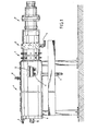
- FIG. 1 an adjustable tube head can be seen, which is seen in the direction of production connected to an extruder, not shown in the drawing.
- a vacuum suction cup 2 which is equipped with a vacuum connection 5 are provided in the measuring devices which adjust the function of the desired pipe outside diameter, the prevailing in the suction cup vacuum, thereby characterized the tubular melt stream the desired outer diameter is set, that is absorbed, wherein in the vacuum suction cup 2 already precooling of the melt strand can be done.
- the vacuum suction cup 2 can be adjusted in conjunction with the adjustable tube head a precise tube wall thickness, the tube wall thickness can be varied depending on the outer diameter of the tube.
- the vacuum suction cup 2 is followed by a calibration station 3.
- this calibration station can be used for all plastics in question.
- several dimensions can also be set with the different wall coverings.
- vacuum calibration 4 In a seen in the direction of production subsequent thereto vacuum calibration 4 then the cooling and curing of the plastic tube is carried out by water spray, in the drawing, a water inlet 6 and a water outlet 7 can be seen. Furthermore, the vacuum calibration bath 4 is followed by a vacuum connection 8 and the tube 10 located in the vacuum calibration bath 4 passes over support rollers 11 which can also be referred to as calibration rollers and can be adjusted to the desired pipe diameter.
- the surface of the tube 10 is relatively hard and the tube 10 leaves the vacuum calibration 4 by a vacuum seal 9, which either automatically adjusts to the tube diameter or is adjusted depending on the set tube dimensions in the calibration station 3 and / or in the vacuum calibration 4 ,
- a vacuum seal 9 can be arranged, which are actuated hydraulically or by mechanical springs, wherein at the same time here in the passage of the pipe water for lubrication and sealing can be introduced.
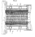
- FIGS. 2 and 3 show sections through an embodiment of the calibration 3. It can be seen that within the outer wall 44 of the calibration a plurality of fins 40 is arranged, which rest over the circumference of the tube 10 distributed on the tube outer wall of the tube 10. The adjacent edge 41 of each blade 40 has a rounding, which corresponds to the largest possible outer diameter of the tube 10. From Fig. 2 and Fig. 3 it can be seen that a plurality of lamellar rings 42 and 43 are arranged one behind the other in the direction of production of the tube.
- positioning motors 45 are provided, which jointly control a common adjustment of all lamellar rings, whereby here too the adjustment of the positioning motors 45 can be controlled centrally with the corresponding control in the suction group 2 and the calibration 4.
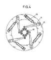
- Fig. 4 shows an embodiment in which a plurality of individual rollers 50 abut against the outer wall of the tube to be produced, wherein the rollers are supported by levers 51, which are movable via adjusting devices, thereby the desired inner diameter of the roller circle can be adjusted.
- the adjusting devices 52 and the levers 51 are arranged on a setting wheel 53 that can be moved circumferentially via a motor device.
Abstract
Description
Die Erfindung bezieht sich auf eine Vorrichtung und ein verfahren zur Herstellung von Kunststoffrohren gemäß dem Oberbegriff des Hauptanspruches.The invention relates to an apparatus and a method for producing plastic pipes according to the preamble of the main claim.
In Kunststoffrohre produzierenden Einrichtungen besteht das Problem, daß Rohre unterschiedlicher Außendurchmesser mit gleichzeitig unterschiedlichen Wanddicke hergestellt werden müssen. Im Stand der Technik ist es dabei erforderlich, daß entsprechend dem Außendurchmesser des Rohres und der gewünschten, üblicherweise in Abhängigkeit des Außendurchmessers genormten Wanddicke des Rohres entsprechende Werkzeuge ausgewechselt werden müssen. Dies bedingt ein Stillsetzen der Maschine, einen hohen Arbeitsaufwand für das Auswechseln der Werkzeuge und Verlust an Kunststoffmaterial, bis das neue Rohr wieder gezogen werden kann. Ein entsprechendes Ziehen des Rohres, um bei einem bestehenden Außendurchmesser ein Rohr geringerer Wandstärke herstellen zu können, verbietet sich deshalb, da die Molekülkette des Kunststoffes gereckt und damit orientiert wird, so daß dadurch die Festigkeit des Rohres negativ beeinflußt wird, der Schrumpf-und die Faltenbildung aber gefördert werden.In plastic pipe producing facilities, there is the problem that pipes of different outer diameter must be made with simultaneously different wall thickness. In the prior art, it is necessary that according to the outer diameter of the tube and the desired, usually standardized as a function of the outer diameter wall thickness of the tube corresponding tools must be replaced. This requires a shutdown of the machine, a lot of work for the replacement of tools and loss of plastic material until the new pipe can be pulled again. A corresponding pulling of the tube in order to produce a tube of lesser wall thickness at an existing outer diameter can prohibits, therefore, since the molecular chain of the plastic is stretched and thus oriented, so that thereby the strength of the tube is adversely affected, the shrinkage and wrinkling are promoted.
Aus der gattungsbildenden DE 24 12 818 ist eine Vorrichtung zum Kalibrieren eines aus einer Strangpresse austretenden Rohres aus thermoplastischem Kunststoff bekannt, wobei bei dieser bekannten Anordnung in Produktionsrichtung des Rohres gesehen, Kalibrierlamellen aufeinanderfolgend angeordnet sind. Jede Kalibrierlamelle weist einen Kalibrierdurchlaß auf, der für alle aufeinanderfolgenden Kalibrierlamellen gleich und unveränderbar ist. Jede Kalibrierlamelle arbeitet mit einem nach oben abhebbaren Lamellensegment zusammen, das während der Anlaufphase der Produktion abgehoben werden kann, so daß das Einlegen des den Extruder bzw. den Rohrkopf verlassenden Rohres in den Kalibrierdurchlaß erleichtert wird. Eine Variation des Rohrdurchmessers während des Produktionsverfahrens ist hier nicht möglich und nicht nahegelegt.From the generic DE 24 12 818 a device for calibrating a leaking from an extruder tube made of thermoplastic material is known, in this known arrangement seen in the production direction of the tube, calibration blades are arranged successively. Each calibration lamella has a calibration passage which is the same and unchangeable for all successive calibration lamellae. Each sizing blade cooperates with an upwardly liftable sipe segment which can be lifted during the start-up phase of production, thus facilitating the insertion of the pipe leaving the extruder or pipe head into the sizing passage. A variation of the pipe diameter during the production process is not possible here and not suggested.
Die US 5,891,481 offenbart eine Kalibrierstation, bei der geringfügige Kalibriereinstellungen dadurch vorgenommen werden können, daß einzelne offene Kalibrierringe geringfügig in ihrem Durchmesser verändert werden können. Bei dieser Anordnung ist allerdings keine Variation von Rohraußendimensionen über Normdimensionen hinweg erreichbar. Durch die Veränderung des Durchmessers der Kalibrierringe kann lediglich dem Schrumpfverhalten entgegengewirkt werden. Dafür ist die relativ geringe Verstellmöglichkeit der Kalibrierringe vollkommen ausreichend.US 5,891,481 discloses a calibration station in which minor calibration adjustments can be made by allowing individual open gauge rings to be slightly varied in diameter. In this arrangement, however, no variation of tube outside dimensions over standard dimensions away reachable. By changing the diameter of the Kalibrierringe only the shrinkage behavior can be counteracted. For the relatively small adjustment of the calibration is completely sufficient.
Aus der US 5,120,212 ist eine Zentriervorrichtung für einen Rohrextrusionskopf bekannt, die bei Rohrextrusionsdüsen mit herkömmlichen radialen Zentrierschrauben eine vollautomatische Nachzentrierung in Abhängigkeit von einer fortlaufend durchgeführten Messung der Wanddicke ermöglicht. Die in dieser Druckschrift offenbarte Vorrichtung umfasst einen Rohrextrusionskopf, in dem ein ringförmiger Düsenspalt zum Extrudieren eines Rohrs vorhanden ist. Das extrudierte Rohr läuft unmittelbar nach dem Verlassen des Düsenspalts in eine Katibrierhutse mit einem an sich bekannten Vakuumbad ein. Ferner ist ein motorbetriebenes Schraubgerät derart um die Extrusionsachse schwenkbar und radial verstellbar gelagert, daß es mit jeder der Zentrierschrauben für das radiale Verstellen der Rohrextrusionsdüsen in Eingriff gebracht werden kann. Die Stellantriebe und der Antriebsmotor des Schraubwerkzeugs werden von einer Rechen- und Steuereinheit in Abhängigkeit von den von einem Ultraschall-Messgerät an mehreren Umfangsstellen des Rohres gemessenen Wanddickenunterschieden.angesteuert. Dadurch kann eine automatische Zentrierung in einem geschlossenen Regelkreis erreicht werden. Eine Änderung der Rohrdimensionen über Normdimensionen hinweg ist während der Produktionsphase allerdings nicht möglich.From US 5,120,212 a centering device for a pipe extrusion head is known, which allows for pipe extrusion nozzles with conventional radial centering a fully automatic recentering in response to a continuous measurement of the wall thickness. The apparatus disclosed in this document comprises a pipe extrusion head in which there is an annular die gap for extruding a pipe. Immediately after leaving the die gap, the extruded tube enters a gasket cap with a vacuum bath known per se. Further, a power screwdriver is pivotally and radially adjustably mounted about the extrusion axis so as to be engageable with each of the centering screws for radially displacing the pipe extrusion nozzles. The actuators and the drive motor of the screwing tool are controlled by a computer and control unit in dependence on the wall thickness differences measured by an ultrasonic measuring instrument at a plurality of peripheral points of the tube. As a result, an automatic centering in a closed loop can be achieved. However, changing the pipe dimensions beyond standard dimensions is not possible during the production phase.
Der Erfindung liegt die Aufgabe zugrunde, eine Vorrichtung zu schaffen, um während der Produktionsphase des Rohres ohne Unterbrechung des Produktionsganges eine vollautomatisch gesteuerte Umstellung zwischen mehreren Kunststoffrohrdimensionen im kontinuierlichen Extrusionsprozeß zu erreichen, wobei der Außendurchmesser und die Rohrwanddicke entsprechend den Kundenwünschen bzw. der Normung aufeinander abgestimmt sind.The invention has for its object to provide a device to achieve during the production phase of the pipe without interrupting the production process a fully automated changeover between several plastic pipe dimensions in a continuous extrusion process, the outer diameter and the pipe wall thickness matched according to customer wishes or standardization are.
Diese der Erfindung zugrundeliegende Aufgabe wird durch die Lehre des Patentanspruches 1 und der Lehre des Verfahrensanspruches 2 gelöst.This object of the invention is achieved by the teaching of claim 1 and the teaching of method claim 2.
Der schon vordimensionierte Massestrang kann gemäß der Erfindung in eine Kalibrierstation eintreten, in der unterschiedliche Rohrdimensionen einstellbar sind.The already pre-dimensioned strand of material can according to the invention enter into a calibration station in which different pipe dimensions can be set.
Ein Ausführungsbeispiel der Erfindung wird nachfolgend anhand der Zeichnungen erläutert. Die Zeichnungen zeigen dabei in
- Fig. 1
- eine Gesamtansicht einer Produktionseinrichtung, in
- Fig. 2
- in Produktionsrichtung gesehen einen Schnitt durch einen Kalibrierkopf, in
- Fig. 3
- im Schnitt gemäß der Linie 3 - 3 in Fig. 2 die hintereinander angeordneten Lamellenkränze und in
- Fig. 4
- eine abgeänderte Ausführungsform.
- Fig. 1
- an overall view of a production facility, in
- Fig. 2
- Seen in the direction of production a section through a calibration, in
- Fig. 3
- in section along the line 3 - 3 in Fig. 2, the successively arranged lamellar rings and in
- Fig. 4
- a modified embodiment.
In Fig. 1 ist ein verstellbarer Rohrkopf erkennbar, der in Produktionsrichtung gesehen an einen in der Zeichnung nicht dargestellten Extruder anschließt. An den verstellbaren Rohrkopf 1 schließt sich eine Vakuum-Saugglocke 2 an, die mit einem Vakuumanschluß 5 ausgerüstet ist, in der Meßvorrichtungen vorgesehen sind, die in Abhängigkeit des gewünschten Rohraußendurchmessers, das in der Saugglocke herrschende Vakuum einstellen, so daß dadurch der rohrförmige Schmelzestrom auf den gewünschten Außendurchmesser eingestellt wird, d. h. aufgesaugt wird, wobei in der Vakuum-Saugglocke 2 bereits eine Vorkühlung des Schmelzestranges erfolgen kann. In der Vakuum-Saugglocke 2 kann in Verbindung mit dem verstellbaren Rohrkopf eine genaue Rohrwanddicke eingestellt werden, wobei die Rohrwanddicke in Abhängigkeit des Außendurchmessers des Rohres variiert werden kann.In Fig. 1, an adjustable tube head can be seen, which is seen in the direction of production connected to an extruder, not shown in the drawing. To the adjustable pipe head 1 is followed by a vacuum suction cup 2, which is equipped with a vacuum connection 5, are provided in the measuring devices which adjust the function of the desired pipe outside diameter, the prevailing in the suction cup vacuum, thereby characterized the tubular melt stream the desired outer diameter is set, that is absorbed, wherein in the vacuum suction cup 2 already precooling of the melt strand can be done. In the vacuum suction cup 2 can be adjusted in conjunction with the adjustable tube head a precise tube wall thickness, the tube wall thickness can be varied depending on the outer diameter of the tube.
An die Vakuum-Saugglocke 2 schließt sich eine Kalibrierstation 3 an. Hier erfolgt durch eine mechanische Zentralverstellung das genaue Kalibrieren des Außendurchmessers des Schmelzestranges und des schon teilweise ausgehärteten Rohres, wobei diese Kalibrierstation für alle in Frage kommenden Kunststoffe einsetzbar ist. In dieser Kalibrierstation können mehrere Dimensionen auch mit den unterschiedlichen Wanddecken eingestellt werden.The vacuum suction cup 2 is followed by a
In einem sich in Produktionsrichtung gesehen daran anschließenden Vakuum-Kalibrierbad 4 erfolgt dann das Auskühlen und Aushärten des Kunststoffrohres durch Sprühwasser, wobei in der Zeichnung ein Wasserzulauf 6 und ein Wasserabfluß 7 erkennbar ist. Weiterhin schließt an das Vakuum-Kalibrierbad 4 ein Vakuumanschluß 8 an und das sich in dem Vakuum-Kalibrierbad 4 befindende Rohr 10 läuft über Stützrollen 11, die auch als Kalibrierrollen bezeichnet werden können und sich auf den gewünschten Rohrdurchmesser einstellen lassen. Die Oberfläche des Rohres 10 ist relativ hart und das Rohr 10 verläßt das Vakuum-Kalibrierbad 4 durch eine Vakuumabdichtung 9, die sich entweder selbständig auf den Rohrdurchmesser einstellt oder in Abhängigkeit der eingestellten Rohrdimensionen in derKalibrierstation 3 und/oder im Vakuum-Kalibrierbad 4 eingestellt wird. In der Vakuumabdichtung 9 können Formrollen angeordnet sein, die hydraulisch oder durch mechanische Federn betätigt werden, wobei gleichzeitig hier in den Durchlauf des Rohres Wasser zur Schmierung und Abdichtung eingeführt werden kann.In a seen in the direction of production subsequent thereto vacuum calibration 4 then the cooling and curing of the plastic tube is carried out by water spray, in the drawing, a
Die Fig. 2 und 3 zeigen Schnitte durch eine Ausführungsform der Kalibrierstation 3. Es ist erkennbar, daß innerhalb der Außenwandung 44 der Kalibrierstation eine Vielzahl von Lamellen 40 angeordnet ist, die über den Umfang des Rohres 10 verteilt an der Rohraußenwandung des Rohres 10 anliegen. Die anliegende Kante 41 jeder Lamelle 40 weist dabei eine Rundung auf, die dem größtmöglichen Außendurchmesser des Rohres 10 entspricht. Aus Fig. 2 und Fig. 3 ist erkennbar, daß eine Vielzahl von Lamellenkränzen 42 und 43 hintereinander in Produktionsrichtung des Rohres gesehen angeordnet sind.2 and 3 show sections through an embodiment of the
Bei der Ausführungsform gemäß Fig. 2 sind Stellmotore 45 vorgesehen, die gemeinsam gesteuert ein gemeinsames Verstellen aller Lamellenkränze bewirken, wobei auch hier die Verstellung der Stellmotore 45 zentral gesteuert mit der entsprechenden Steuerung in der Sauggruppe 2 und dem Kalibrierbad 4 erfolgen kann.In the embodiment according to FIG. 2,
Fig. 4 zeigt eine Ausführungsform, bei der eine Vielzahl von Einzelrollen 50 an der Außenwand des herzustellenden Rohres anliegen, wobei die Rollen von Hebel 51 getragen werden, die über Stellvorrichtungen beweglich sind, so daß dadurch der gewünschte Innendurchmesser des Rollenkreises eingestellt werden kann. Die Stellvorrichtungen 52 und die Hebel 51 sind an einem Stellrad 53 angeordnet, daß über eine motorische Einrichtung umlaufend bewegt werden kann.Fig. 4 shows an embodiment in which a plurality of
Claims (2)
- Device for the production of plastics pipes with an extruder, a pipe die head (1), which adjoins the extruder in the direction of production and the melt gap of which can be adjusted during the production phase, and a calibrating station (3), in which calibrating dies lie against the outer wall of the pipe (10), characterized in that- the outlet of the pipe die head (1) is adjoined by a vacuum suction bell (2), which acts on the outer side of the not yet cured pipe (10) and in which the diameter of the melt strand can be changed in a controlled manner by setting the vacuum,- different pipe diameters can be set during the production phase by means of the calibrating dies in the calibrating station (3) adjoining the vacuum suction bell (2),- a vacuum calibrating bath (4) is provided, which adjoins the calibrating station (3) and in which the pipe (10) can be cooled and cured, the vacuum calibrating bath (4) having a vacuum calibrating bath outlet, which is provided with a vacuum seal (9), which sets itself automatically to the pipe diameter.
- Method for the production of plastics pipes with an extruder, a pipe die head (1), which adjoins the extruder in the direction of production, a vacuum suction bell (2), which adjoins the outlet of the pipe die head (1), and a calibrating station (3), in which calibrating dies can be brought to bear against the outer wall of the pipe (10), in which method:- the melt gap of the pipe die head (1) is adjusted during the production phase,- the diameter of the melt strand is changed in a controlled manner by setting the vacuum in the vacuum suction bell (2),- different pipe diameters are set in the calibrating station (3) during the production phase,- the pipe (10) is cooled and cured in a vacuum calibrating bath (4) adjoining the calibrating station (3).
Applications Claiming Priority (3)
| Application Number | Priority Date | Filing Date | Title |
|---|---|---|---|
| DE19843340 | 1998-09-22 | ||
| DE19843340A DE19843340C2 (en) | 1998-09-22 | 1998-09-22 | Device for the production of plastic pipes |
| EP99969371A EP1115550B1 (en) | 1998-09-22 | 1999-08-24 | Device for producing plastic pipes |
Related Parent Applications (1)
| Application Number | Title | Priority Date | Filing Date |
|---|---|---|---|
| EP99969371A Division EP1115550B1 (en) | 1998-09-22 | 1999-08-24 | Device for producing plastic pipes |
Publications (3)
| Publication Number | Publication Date |
|---|---|
| EP1249331A2 EP1249331A2 (en) | 2002-10-16 |
| EP1249331A3 EP1249331A3 (en) | 2002-11-13 |
| EP1249331B1 true EP1249331B1 (en) | 2006-05-31 |
Family
ID=7881771
Family Applications (2)
| Application Number | Title | Priority Date | Filing Date |
|---|---|---|---|
| EP02015151A Expired - Lifetime EP1249331B1 (en) | 1998-09-22 | 1999-08-24 | Device and method for the production of plastics pipes |
| EP99969371A Expired - Lifetime EP1115550B1 (en) | 1998-09-22 | 1999-08-24 | Device for producing plastic pipes |
Family Applications After (1)
| Application Number | Title | Priority Date | Filing Date |
|---|---|---|---|
| EP99969371A Expired - Lifetime EP1115550B1 (en) | 1998-09-22 | 1999-08-24 | Device for producing plastic pipes |
Country Status (9)
| Country | Link |
|---|---|
| US (1) | US7335010B2 (en) |
| EP (2) | EP1249331B1 (en) |
| CN (2) | CN1272160C (en) |
| AT (2) | ATE237457T1 (en) |
| DE (3) | DE19843340C2 (en) |
| DK (2) | DK1115550T3 (en) |
| ES (2) | ES2192102T3 (en) |
| PT (2) | PT1249331E (en) |
| WO (1) | WO2000016962A1 (en) |
Cited By (1)
| Publication number | Priority date | Publication date | Assignee | Title |
|---|---|---|---|---|
| CN104999645A (en) * | 2015-06-16 | 2015-10-28 | 凤阳九龙新型建材有限公司 | PVC pipe production technology |
Families Citing this family (51)
| Publication number | Priority date | Publication date | Assignee | Title |
|---|---|---|---|---|
| DK1048434T3 (en) * | 1999-04-21 | 2003-05-26 | Conpro Gmbh | Calibration sleeve with variable diameter adjustment |
| EP1157805B1 (en) * | 2000-05-22 | 2003-02-12 | K. Sandern Maschinenbau GmbH | Calibrating sleeve for extruded plastic tube |
| DE10206276B4 (en) * | 2002-02-15 | 2005-07-14 | Egeplast Werner Strumann Gmbh & Co. Kg | Self-leveling end seal of a vacuum calibration bath adjusting to the pipe diameter |
| DE10315125B3 (en) | 2003-04-03 | 2004-09-09 | Krauss-Maffei Kunststofftechnik Gmbh | Calibration unit for endless extruded profiles, comprises numerous segment crown sections formed from individual segments, and a carrier structure |
| AU2003901596A0 (en) * | 2003-04-08 | 2003-05-01 | Uponor Innovation Ab | Method and apparatus for control of plastics tube orientation process |
| DE10318137B3 (en) * | 2003-04-17 | 2005-01-27 | Inoex Gmbh | Infinitely adjustable calibration sleeve for extruded plastic strands, in particular plastic pipes |
| DE10323543B4 (en) | 2003-05-24 | 2005-02-10 | Krauss-Maffei Kunststofftechnik Gmbh | calibration |
| DE10324187B4 (en) * | 2003-05-28 | 2006-10-26 | Krauss-Maffei Kunststofftechnik Gmbh | Combined roller for pipe extrusion line |
| DE10324475B4 (en) * | 2003-05-30 | 2007-08-02 | Krauss-Maffei Kunststofftechnik Gmbh | calibration |
| DE10337533B4 (en) * | 2003-08-14 | 2006-04-06 | Krauss-Maffei Kunststofftechnik Gmbh | Easy to install, adjustable calibration device |
| DE10337964B4 (en) * | 2003-08-19 | 2007-04-26 | Egeplast Werner Strumann Gmbh & Co. Kg | Method and device for producing plastic pipes |
| DE102004008620B3 (en) * | 2004-02-21 | 2005-10-13 | Egeplast Werner Strumann Gmbh & Co. Kg | Calibration basket for a calibration station |
| DE102004029498B3 (en) * | 2004-06-18 | 2005-10-13 | INOEX GmbH Innovationen und Ausrüstungen für die Extrusionstechnik | Adjustable calibrating sleeve for plastic pipes comprises inlet head, across which overlapping radial plates are mounted, two sets of spiral wound strips being attached to these which are connected by pivots at points where they cross |
| DE102004039316A1 (en) | 2004-08-13 | 2006-02-23 | Inoex Gmbh | Method and device for producing plastic pipes in an extrusion line |
| DE102004052973B4 (en) * | 2004-10-29 | 2009-03-05 | Battenfeld Extrusionstechnik Gmbh | support device |
| DE102004059515B3 (en) * | 2004-12-10 | 2006-05-11 | Inoex Gmbh | Support for extruded profiles, in particular pipes, on extrusion line comprises rotatable cylinder section having conical channel with increasing width from one end to the other |
| DE102005002820B3 (en) | 2005-01-20 | 2006-05-11 | Inoex Gmbh | Stepless adjustable calibration sleeve for extruded plastic pipe comprises overlapping toothed radial segments and variable braid and segment ends contact pipe and connect to segments with flush joints |
| DE102005003860B4 (en) * | 2005-01-27 | 2011-04-28 | Egeplast Werner Strumann Gmbh & Co. Kg | calibration |
| DE102005010808A1 (en) * | 2005-03-07 | 2006-06-29 | Battenfeld Extrusionstechnik Gmbh | Open or closed loop control of extrusion line for plastic profiles, in particular pipes, knows extrusion speed relative to extrusion line length and automatically resets each plant unit for new profile at correct time during extrusion |
| DE102005020296B4 (en) * | 2005-04-30 | 2010-06-02 | Battenfeld Extrusionstechnik Gmbh | Device for profile extrusion |
| DE102005028084B4 (en) * | 2005-06-17 | 2010-03-11 | Cincinnati Extrusion Gmbh | Method and device for changing a calibration device |
| EP1749638A1 (en) * | 2005-08-03 | 2007-02-07 | Zumbach Electronic Ag | Device for measuring the thickness of extruded tubes |
| US7829164B2 (en) | 2005-10-07 | 2010-11-09 | Pirelli & C. S.P.A. | Utility pole of thermoplastic composite material |
| DE102005060099B4 (en) * | 2005-12-16 | 2015-02-05 | Battenfeld-Cincinnati Germany Gmbh | Method for supporting a plastic melt |
| DE102005063041B4 (en) * | 2005-12-29 | 2013-08-08 | Inoex Gmbh | Infinitely adjustable calibration sleeve for extruded plastic pipes |
| US7758331B2 (en) * | 2006-02-22 | 2010-07-20 | American Maplan Corporation | Pipe support system |
| DE102007015065A1 (en) | 2007-03-29 | 2008-10-02 | Kraussmaffei Technologies Gmbh | PVC foam core pipes |
| FI20070284A (en) * | 2007-04-13 | 2008-11-03 | Kwh Pipe Ab Oy | calibrator |
| DE102007019854A1 (en) | 2007-04-25 | 2008-10-30 | Inoex Gmbh | Method for producing tubular plastic profiles |
| DE102007050938A1 (en) | 2007-10-23 | 2009-04-30 | Inoex Gmbh | Infinitely adjustable calibration sleeve for extruded plastic pipes |
| DE102009010396A1 (en) | 2009-02-26 | 2010-09-02 | Egeplast Werner Strumann Gmbh & Co. Kg | Method for producing and sheathing plastic pipes or metal pipes |
| EP2227942B1 (en) * | 2009-03-10 | 2012-05-30 | THE Machines Yvonand SA | Method for producing a drip watering pipe |
| DE102009016100A1 (en) | 2009-04-03 | 2010-10-07 | Egeplast Werner Strumann Gmbh & Co. Kg | Calibrating device for plastic pipe extruding system, has calibrating tools formed as hollow body, where tools have slots in area of sliding surfaces that are attached to pipe circumference, and slots are connected with cavity in body |
| AT508213B1 (en) * | 2009-04-07 | 2011-09-15 | Amx Automation Technologies Gmbh | DEVICE FOR CALIBRATING PROFILES |
| DE102012106035A1 (en) * | 2012-07-05 | 2014-01-09 | Kraussmaffei Technologies Gmbh | Seal for use in an extrusion device |
| DE102013209703B4 (en) * | 2013-05-24 | 2017-03-30 | Greiner Tool.Tec Gmbh | Calibration device, calibration method and method for producing a calibration device |
| DE102013220619A1 (en) * | 2013-10-12 | 2015-04-16 | Battenfeld-Cincinnati Germany Gmbh | Device for fixing extruded plastic profile |
| CN105291403A (en) * | 2015-11-10 | 2016-02-03 | 上海天力实业(集团)有限公司 | Method and device for reducing axial stress concentration of thermoplastic plastic pipe |
| CN109049624A (en) * | 2018-08-17 | 2018-12-21 | 海南联塑科技实业有限公司 | A kind of adjustable shaping cover of PVC |
| DE102019002022A1 (en) | 2019-03-21 | 2020-09-24 | Kraussmaffei Technologies Gmbh | Lamella block with laterally offset lamellae |
| DE102019002004A1 (en) | 2019-03-21 | 2020-09-24 | Kraussmaffei Technologies Gmbh | Lamella block with internal temperature control |
| DE102019002005A1 (en) * | 2019-03-21 | 2020-09-24 | Kraussmaffei Technologies Gmbh | Lamellar block for a calibration device with internal bar |
| DE102019002008A1 (en) * | 2019-03-21 | 2020-09-24 | Kraussmaffei Technologies Gmbh | Lamella block with continuously varied lamella width |
| DE102019002018A1 (en) | 2019-03-21 | 2020-09-24 | Kraussmaffei Technologies Gmbh | Lamella block for a calibration device |
| DE102019002011A1 (en) | 2019-03-21 | 2020-09-24 | Kraussmaffei Technologies Gmbh | Slat block with offset slats |
| DE102019002007A1 (en) | 2019-03-21 | 2020-09-24 | Kraussmaffei Technologies Gmbh | Lamellar block for a calibration device with internal bar |
| DE102019002027A1 (en) | 2019-03-21 | 2020-09-24 | Kraussmaffei Technologies Gmbh | Lamellar block with lamellar openings |
| DE102019002019A1 (en) | 2019-03-21 | 2020-09-24 | Kraussmaffei Technologies Gmbh | Calibration basket with staggered intersections |
| DE102019002025A1 (en) | 2019-03-21 | 2020-09-24 | Kraussmaffei Technologies Gmbh | Lamella block with continuously varied lamella pitch |
| CN110588028B (en) * | 2019-09-28 | 2020-06-30 | 诸暨市合纵科技有限公司 | Gluing repair equipment for compensating damage of electric wire |
| CN112721083B (en) * | 2020-12-10 | 2022-06-14 | 安徽长荣光纤光缆科技有限公司 | Special optical cable extrusion die and use method thereof |
Family Cites Families (23)
| Publication number | Priority date | Publication date | Assignee | Title |
|---|---|---|---|---|
| BE488618A (en) * | 1948-10-27 | 1900-01-01 | ||
| FR2027408A1 (en) | 1968-12-31 | 1970-09-25 | Shell Int Research | |
| DE1923490A1 (en) | 1969-05-08 | 1970-11-12 | Motor Patent Ag | Calibrated hollow shapes from extruded the- - rmoplastic material |
| GB1380397A (en) | 1971-05-12 | 1975-01-15 | British Insulated Callenders | Elastic memory tubing |
| DE2210657C3 (en) * | 1972-03-06 | 1984-05-17 | Plastic-Werk A. U. G. Scherer & Trier Ohg, 8626 Michelau | Method and device for calibrating the extrusion of hollow profiles made of thermoplastic material |
| DE2357138C3 (en) | 1973-11-15 | 1978-08-03 | Windmoeller & Hoelscher, 4540 Lengerich | After-cooling device for blown films made of thermoplastics |
| DE2359975C3 (en) * | 1973-12-01 | 1980-09-18 | Hoechst Ag, 6000 Frankfurt | Cooling device for tubular films |
| DE2412818A1 (en) * | 1974-03-16 | 1975-09-25 | Bellaplast Maschinenbau Gmbh | Calibrator for extruded thermoplastics tube - comprising two sets of plates which can be opened to introduce pipe |
| US3980418A (en) | 1975-09-05 | 1976-09-14 | Gloucester Engineering Co. Inc. | Guide assembly for air-expanded thermoplastic tubes |
| US4355966A (en) | 1981-05-04 | 1982-10-26 | E. B. Westlake, Jr. | Automatic control of bubble size in blown film |
| US4683094A (en) | 1985-03-18 | 1987-07-28 | Mobil Oil Corporation | Process for producing oriented polyolefin films with enhanced physical properties |
| DE3521321A1 (en) * | 1985-06-14 | 1986-12-18 | Battenfeld Extrusionstechnik GmbH, 4970 Bad Oeynhausen | Infinitely variable calibrator for plastics extrudates |
| GB8527300D0 (en) * | 1985-11-06 | 1985-12-11 | Victaulic Plc | Extrusion of products |
| DE8706688U1 (en) | 1987-05-09 | 1987-07-02 | Reifenhaeuser Gmbh & Co Maschinenfabrik, 5210 Troisdorf, De | |
| DE3829234A1 (en) * | 1988-08-29 | 1990-03-08 | Nittel Gmbh & Co Kg | METHOD AND DEVICE FOR THE PRODUCTION OF TUBE FILMS |
| AT401031B (en) | 1988-11-18 | 1996-05-28 | Cincinnati Milacron Austria | DEVICE FOR REGULATING THE WALL THICKNESS |
| DE4002884C2 (en) * | 1989-09-28 | 1998-08-13 | Cincinnati Milacron Austria | Device for extruding pipes with an extrusion press |
| ATE99596T1 (en) * | 1989-10-31 | 1994-01-15 | Inoex Gmbh | EXTRUDING PLANT FOR PLASTIC PIPES. |
| DE3936496A1 (en) * | 1989-11-02 | 1991-05-08 | Krauss Maffei Ag | CENTERING DEVICE FOR A TUBE EXTRUSION HEAD |
| DE4135339A1 (en) * | 1991-10-26 | 1993-04-29 | Conpro Gmbh | Wall thickness meter for extrusions - has ultrasonic heads enabling speed of sound through extrusion to be measured, and further test heads use this to provide thickness values |
| US5945138A (en) * | 1994-04-07 | 1999-08-31 | Advanced Drainage Systems, Inc. | Cam adjustable former for plastic pipe |
| US5891481A (en) * | 1995-05-17 | 1999-04-06 | Pedersen; Knud Kristian | Tubular calibration unit for machines for extruding plastic strings such as pipes |
| US5700489A (en) * | 1996-04-08 | 1997-12-23 | Pearl Technologies, Inc. | Bubble stabilizer and sizing cage with wear strips |
-
1998
- 1998-09-22 DE DE19843340A patent/DE19843340C2/en not_active Expired - Lifetime
-
1999
- 1999-08-24 WO PCT/DE1999/002708 patent/WO2000016962A1/en active IP Right Grant
- 1999-08-24 DK DK99969371T patent/DK1115550T3/en active
- 1999-08-24 ES ES99969371T patent/ES2192102T3/en not_active Expired - Lifetime
- 1999-08-24 PT PT02015151T patent/PT1249331E/en unknown
- 1999-08-24 AT AT99969371T patent/ATE237457T1/en active
- 1999-08-24 CN CNB031239315A patent/CN1272160C/en not_active Expired - Fee Related
- 1999-08-24 EP EP02015151A patent/EP1249331B1/en not_active Expired - Lifetime
- 1999-08-24 AT AT02015151T patent/ATE327880T1/en active
- 1999-08-24 DE DE59913496T patent/DE59913496D1/en not_active Expired - Lifetime
- 1999-08-24 DK DK02015151T patent/DK1249331T3/en active
- 1999-08-24 EP EP99969371A patent/EP1115550B1/en not_active Expired - Lifetime
- 1999-08-24 CN CN99811201A patent/CN1119227C/en not_active Expired - Fee Related
- 1999-08-24 ES ES02015151T patent/ES2266353T3/en not_active Expired - Lifetime
- 1999-08-24 PT PT99969371T patent/PT1115550E/en unknown
- 1999-08-24 DE DE59905099T patent/DE59905099D1/en not_active Expired - Lifetime
-
2005
- 2005-09-19 US US11/229,794 patent/US7335010B2/en not_active Expired - Lifetime
Cited By (1)
| Publication number | Priority date | Publication date | Assignee | Title |
|---|---|---|---|---|
| CN104999645A (en) * | 2015-06-16 | 2015-10-28 | 凤阳九龙新型建材有限公司 | PVC pipe production technology |
Also Published As
| Publication number | Publication date |
|---|---|
| EP1115550B1 (en) | 2003-04-16 |
| US7335010B2 (en) | 2008-02-26 |
| PT1115550E (en) | 2003-08-29 |
| CN1319045A (en) | 2001-10-24 |
| PT1249331E (en) | 2006-10-31 |
| ATE237457T1 (en) | 2003-05-15 |
| CN1473699A (en) | 2004-02-11 |
| ATE327880T1 (en) | 2006-06-15 |
| DE19843340C2 (en) | 2001-11-22 |
| DK1249331T3 (en) | 2006-10-02 |
| CN1119227C (en) | 2003-08-27 |
| DE59905099D1 (en) | 2003-05-22 |
| DK1115550T3 (en) | 2003-07-07 |
| EP1249331A3 (en) | 2002-11-13 |
| CN1272160C (en) | 2006-08-30 |
| US20060034965A1 (en) | 2006-02-16 |
| EP1249331A2 (en) | 2002-10-16 |
| DE59913496D1 (en) | 2006-07-06 |
| WO2000016962A1 (en) | 2000-03-30 |
| ES2192102T3 (en) | 2003-09-16 |
| EP1115550A1 (en) | 2001-07-18 |
| DE19843340A1 (en) | 2000-04-06 |
| ES2266353T3 (en) | 2007-03-01 |
Similar Documents
| Publication | Publication Date | Title |
|---|---|---|
| EP1249331B1 (en) | Device and method for the production of plastics pipes | |
| EP0563575A2 (en) | Method and apparatus for continuous production of a composite pipe with sleeve | |
| DE4013610C2 (en) | ||
| DE19843339B4 (en) | Method and device for producing plastic pipes | |
| WO2005080064A1 (en) | Calibration basket for a calibration station | |
| EP1736297A1 (en) | Controllable gas cooling ring with rectifying unit and method for controlling and/or regulating a gas cooling ring during the manufacture of blown thermoplastic films | |
| EP1363766B1 (en) | Method and device for producing a double-walled thermoplastic pipe with integral pipe bell | |
| DE2459785B1 (en) | INTERNAL COOLING DEVICE FOR PLASTIC TUBE FILMS, FITTED TO A BLOW HEAD WITH AN ANNUAL SPLIT NOZZLE THAT CAN BE CONNECTED TO A SCREW EXTRUSION PRESS | |
| EP1207999B1 (en) | Tyre building apparatus with press units | |
| EP1914060B1 (en) | Device for extruding hollow rods | |
| DE4218997C1 (en) | Appts. for prodn. of plastic film from extrude blown tubing - produces close tolerances by dividing cooling system into segments of circumference of blowing nozzle each with finely controlled valve | |
| DE19724857C1 (en) | Rapid production of large-diameter, cut lengths of corrugated plastic tubing | |
| DE10337964B4 (en) | Method and device for producing plastic pipes | |
| WO2000016960A1 (en) | Device for producing plastic pipes | |
| EP1627724A2 (en) | Device and process for the production of plastic pipes in an extrusion line | |
| DE10206276A1 (en) | End seal for an underpressure calibration bath, in the production of plastics pipes, has a lamella seal with sealing segments around the pipe to move in guides and form a seal at the circumference automatically or under control | |
| EP1108522A1 (en) | Process and apparatus to modify the volume flow of a fan | |
| EP0253216A2 (en) | Apparatus for manufacturing plastic sheets | |
| DE19829183A1 (en) | Separating arrangement avoiding direct contact between moveable inserts forming different nozzle cross-sections and polymer melt in the flow channel | |
| DE4218993C1 (en) | Fault-free blown film tubing prodn. - using machine with extruding nozzle and air cooling system fitted with circumferential gauges connected to computer to correct deviations | |
| DE102005060099B4 (en) | Method for supporting a plastic melt | |
| DE102015219221A1 (en) | Spray head for a device for producing a composite pipe | |
| DE10164897B4 (en) | Method and device for producing a double-walled thermoplastic pipe with a pipe socket | |
| DE102006042110A1 (en) | Process and assembly to calibrate the diameter of an extruded plastic pipe | |
| DE19821856A1 (en) | Process for producing blown films and device for carrying out the process |
Legal Events
| Date | Code | Title | Description |
|---|---|---|---|
| PUAI | Public reference made under article 153(3) epc to a published international application that has entered the european phase |
Free format text: ORIGINAL CODE: 0009012 |
|
| PUAL | Search report despatched |
Free format text: ORIGINAL CODE: 0009013 |
|
| AC | Divisional application: reference to earlier application |
Ref document number: 1115550 Country of ref document: EP |
|
| AK | Designated contracting states |
Kind code of ref document: A2 Designated state(s): AT BE CH CY DE DK ES FI FR GB GR IE IT LI LU MC NL PT SE |
|
| AK | Designated contracting states |
Kind code of ref document: A3 Designated state(s): AT BE CH CY DE DK ES FI FR GB GR IE IT LI LU MC NL PT SE |
|
| RIC1 | Information provided on ipc code assigned before grant |
Free format text: 7B 29C 47/90 A, 7B 29C 47/92 B, 7B 29C 47/22 B |
|
| 17P | Request for examination filed |
Effective date: 20021130 |
|
| AKX | Designation fees paid |
Designated state(s): AT BE CH CY DE DK ES FI FR GB GR IE IT LI LU MC NL PT SE |
|
| 17Q | First examination report despatched |
Effective date: 20050614 |
|
| GRAP | Despatch of communication of intention to grant a patent |
Free format text: ORIGINAL CODE: EPIDOSNIGR1 |
|
| RTI1 | Title (correction) |
Free format text: DEVICE AND METHOD FOR THE PRODUCTION OF PLASTICS PIPES |
|
| GRAS | Grant fee paid |
Free format text: ORIGINAL CODE: EPIDOSNIGR3 |
|
| GRAA | (expected) grant |
Free format text: ORIGINAL CODE: 0009210 |
|
| AC | Divisional application: reference to earlier application |
Ref document number: 1115550 Country of ref document: EP Kind code of ref document: P |
|
| AK | Designated contracting states |
Kind code of ref document: B1 Designated state(s): AT BE CH CY DE DK ES FI FR GB GR IE IT LI LU MC NL PT SE |
|
| REG | Reference to a national code |
Ref country code: CH Ref legal event code: EP Ref country code: GB Ref legal event code: FG4D Free format text: NOT ENGLISH |
|
| REG | Reference to a national code |
Ref country code: IE Ref legal event code: FG4D Free format text: LANGUAGE OF EP DOCUMENT: GERMAN |
|
| REF | Corresponds to: |
Ref document number: 59913496 Country of ref document: DE Date of ref document: 20060706 Kind code of ref document: P |
|
| PG25 | Lapsed in a contracting state [announced via postgrant information from national office to epo] |
Ref country code: MC Free format text: LAPSE BECAUSE OF NON-PAYMENT OF DUE FEES Effective date: 20060831 |
|
| REG | Reference to a national code |
Ref country code: SE Ref legal event code: TRGR |
|
| REG | Reference to a national code |
Ref country code: DK Ref legal event code: T3 |
|
| REG | Reference to a national code |
Ref country code: GR Ref legal event code: EP Ref document number: 20060402820 Country of ref document: GR |
|
| GBT | Gb: translation of ep patent filed (gb section 77(6)(a)/1977) |
Effective date: 20060919 |
|
| REG | Reference to a national code |
Ref country code: PT Ref legal event code: SC4A Effective date: 20060825 |
|
| RAP2 | Party data changed (patent owner data changed or rights of a patent transferred) |
Owner name: KRAUSS-MAFFEI KUNSTSTOFFTECHNIK GMBH Owner name: EGEPLAST WERNER STRUMANN GMBH & CO. KG |
|
| REG | Reference to a national code |
Ref country code: CH Ref legal event code: NV Representative=s name: KIRKER & CIE SA Ref country code: CH Ref legal event code: PUE Owner name: KRAUSS-MAFFEI KUNSTSTOFFTECHNIK GMBH Free format text: EGEPLAST WERNER STRUMANN GMBH & CO. KG#ROBERT-BOSCH-STRASSE 7#48268 GREVEN (DE) -TRANSFER TO- KRAUSS-MAFFEI KUNSTSTOFFTECHNIK GMBH#KRAUSS-MAFFEI STRASSE 2#80997 MUENCHEN (DE) |
|
| REG | Reference to a national code |
Ref country code: PT Ref legal event code: PC4A Owner name: KRAUSS-MAFFEI VERKEHRSTECHNIK GMBH, DE Effective date: 20061113 |
|
| NLT2 | Nl: modifications (of names), taken from the european patent patent bulletin |
Owner name: EGEPLAST Effective date: 20061102 |
|
| ET | Fr: translation filed | ||
| REG | Reference to a national code |
Ref country code: ES Ref legal event code: FG2A Ref document number: 2266353 Country of ref document: ES Kind code of ref document: T3 |
|
| PLBE | No opposition filed within time limit |
Free format text: ORIGINAL CODE: 0009261 |
|
| STAA | Information on the status of an ep patent application or granted ep patent |
Free format text: STATUS: NO OPPOSITION FILED WITHIN TIME LIMIT |
|
| 26N | No opposition filed |
Effective date: 20070301 |
|
| PG25 | Lapsed in a contracting state [announced via postgrant information from national office to epo] |
Ref country code: LU Free format text: LAPSE BECAUSE OF NON-PAYMENT OF DUE FEES Effective date: 20060824 |
|
| PG25 | Lapsed in a contracting state [announced via postgrant information from national office to epo] |
Ref country code: CY Free format text: LAPSE BECAUSE OF FAILURE TO SUBMIT A TRANSLATION OF THE DESCRIPTION OR TO PAY THE FEE WITHIN THE PRESCRIBED TIME-LIMIT Effective date: 20060531 |
|
| PGFP | Annual fee paid to national office [announced via postgrant information from national office to epo] |
Ref country code: ES Payment date: 20090821 Year of fee payment: 11 Ref country code: IE Payment date: 20090821 Year of fee payment: 11 |
|
| PGFP | Annual fee paid to national office [announced via postgrant information from national office to epo] |
Ref country code: FI Payment date: 20090814 Year of fee payment: 11 Ref country code: PT Payment date: 20090807 Year of fee payment: 11 |
|
| PGFP | Annual fee paid to national office [announced via postgrant information from national office to epo] |
Ref country code: GR Payment date: 20090825 Year of fee payment: 11 |
|
| REG | Reference to a national code |
Ref country code: PT Ref legal event code: MM4A Free format text: LAPSE DUE TO NON-PAYMENT OF FEES Effective date: 20110224 |
|
| PG25 | Lapsed in a contracting state [announced via postgrant information from national office to epo] |
Ref country code: PT Free format text: LAPSE BECAUSE OF NON-PAYMENT OF DUE FEES Effective date: 20110224 Ref country code: FI Free format text: LAPSE BECAUSE OF NON-PAYMENT OF DUE FEES Effective date: 20100824 |
|
| PG25 | Lapsed in a contracting state [announced via postgrant information from national office to epo] |
Ref country code: GR Free format text: LAPSE BECAUSE OF NON-PAYMENT OF DUE FEES Effective date: 20110302 |
|
| PG25 | Lapsed in a contracting state [announced via postgrant information from national office to epo] |
Ref country code: IE Free format text: LAPSE BECAUSE OF NON-PAYMENT OF DUE FEES Effective date: 20100824 |
|
| REG | Reference to a national code |
Ref country code: ES Ref legal event code: FD2A Effective date: 20111019 |
|
| PG25 | Lapsed in a contracting state [announced via postgrant information from national office to epo] |
Ref country code: ES Free format text: LAPSE BECAUSE OF NON-PAYMENT OF DUE FEES Effective date: 20100825 |
|
| REG | Reference to a national code |
Ref country code: DE Ref legal event code: R082 Ref document number: 59913496 Country of ref document: DE Representative=s name: FRITZ & BRANDENBURG PATENTANWAELTE, DE |
|
| REG | Reference to a national code |
Ref country code: DE Ref legal event code: R082 Ref document number: 59913496 Country of ref document: DE Representative=s name: FRITZ & BRANDENBURG PATENTANWAELTE, DE Effective date: 20130628 Ref country code: DE Ref legal event code: R081 Ref document number: 59913496 Country of ref document: DE Owner name: EGEPLAST INTERNATIONAL GMBH, DE Free format text: FORMER OWNER: EGEPLAST WERNER STRUMANN GMBH & CO. KG, 48268 GREVEN, DE Effective date: 20130628 Ref country code: DE Ref legal event code: R082 Ref document number: 59913496 Country of ref document: DE Representative=s name: PATENTANWAELTE FRITZ & BRANDENBURG, DE Effective date: 20130628 |
|
| REG | Reference to a national code |
Ref country code: FR Ref legal event code: PLFP Year of fee payment: 17 |
|
| REG | Reference to a national code |
Ref country code: FR Ref legal event code: PLFP Year of fee payment: 18 |
|
| REG | Reference to a national code |
Ref country code: FR Ref legal event code: PLFP Year of fee payment: 19 |
|
| PGFP | Annual fee paid to national office [announced via postgrant information from national office to epo] |
Ref country code: SE Payment date: 20170821 Year of fee payment: 19 |
|
| REG | Reference to a national code |
Ref country code: FR Ref legal event code: PLFP Year of fee payment: 20 |
|
| PGFP | Annual fee paid to national office [announced via postgrant information from national office to epo] |
Ref country code: NL Payment date: 20180821 Year of fee payment: 20 Ref country code: IT Payment date: 20180830 Year of fee payment: 20 Ref country code: FR Payment date: 20180827 Year of fee payment: 20 Ref country code: DE Payment date: 20180903 Year of fee payment: 20 |
|
| REG | Reference to a national code |
Ref country code: DE Ref legal event code: R079 Ref document number: 59913496 Country of ref document: DE Free format text: PREVIOUS MAIN CLASS: B29C0047900000 Ipc: B29C0048900000 |
|
| PGFP | Annual fee paid to national office [announced via postgrant information from national office to epo] |
Ref country code: AT Payment date: 20180822 Year of fee payment: 20 Ref country code: GB Payment date: 20180822 Year of fee payment: 20 Ref country code: CH Payment date: 20180822 Year of fee payment: 20 Ref country code: DK Payment date: 20180823 Year of fee payment: 20 Ref country code: BE Payment date: 20180821 Year of fee payment: 20 |
|
| REG | Reference to a national code |
Ref country code: SE Ref legal event code: EUG |
|
| PG25 | Lapsed in a contracting state [announced via postgrant information from national office to epo] |
Ref country code: SE Free format text: LAPSE BECAUSE OF NON-PAYMENT OF DUE FEES Effective date: 20180825 |
|
| REG | Reference to a national code |
Ref country code: DE Ref legal event code: R071 Ref document number: 59913496 Country of ref document: DE |
|
| REG | Reference to a national code |
Ref country code: DK Ref legal event code: EUP Effective date: 20190824 |
|
| REG | Reference to a national code |
Ref country code: NL Ref legal event code: MK Effective date: 20190823 |
|
| REG | Reference to a national code |
Ref country code: CH Ref legal event code: PL |
|
| REG | Reference to a national code |
Ref country code: GB Ref legal event code: PE20 Expiry date: 20190823 |
|
| REG | Reference to a national code |
Ref country code: BE Ref legal event code: MK Effective date: 20190824 |
|
| REG | Reference to a national code |
Ref country code: AT Ref legal event code: MK07 Ref document number: 327880 Country of ref document: AT Kind code of ref document: T Effective date: 20190824 |
|
| PG25 | Lapsed in a contracting state [announced via postgrant information from national office to epo] |
Ref country code: GB Free format text: LAPSE BECAUSE OF EXPIRATION OF PROTECTION Effective date: 20190823 |