EP1248330A1 - Prise électrique de puissance de véhicule automobile comportant un dispositif intégré d'éclairage - Google Patents
Prise électrique de puissance de véhicule automobile comportant un dispositif intégré d'éclairage Download PDFInfo
- Publication number
- EP1248330A1 EP1248330A1 EP02290715A EP02290715A EP1248330A1 EP 1248330 A1 EP1248330 A1 EP 1248330A1 EP 02290715 A EP02290715 A EP 02290715A EP 02290715 A EP02290715 A EP 02290715A EP 1248330 A1 EP1248330 A1 EP 1248330A1
- Authority
- EP
- European Patent Office
- Prior art keywords
- connector
- insulating body
- lamp
- socket
- electrical
- Prior art date
- Legal status (The legal status is an assumption and is not a legal conclusion. Google has not performed a legal analysis and makes no representation as to the accuracy of the status listed.)
- Granted
Links
- 230000000295 complement effect Effects 0.000 claims abstract description 13
- 239000011810 insulating material Substances 0.000 claims abstract 2
- 239000012212 insulator Substances 0.000 claims description 6
- 230000004907 flux Effects 0.000 claims description 4
- 239000002991 molded plastic Substances 0.000 claims description 2
- 238000005286 illumination Methods 0.000 abstract 1
- 208000031968 Cadaver Diseases 0.000 description 10
- 210000000078 claw Anatomy 0.000 description 4
- 230000002093 peripheral effect Effects 0.000 description 4
- 210000004027 cell Anatomy 0.000 description 3
- 239000000463 material Substances 0.000 description 3
- 238000000465 moulding Methods 0.000 description 3
- 230000000717 retained effect Effects 0.000 description 3
- 239000004020 conductor Substances 0.000 description 2
- 238000004519 manufacturing process Methods 0.000 description 2
- 239000002184 metal Substances 0.000 description 2
- 238000012550 audit Methods 0.000 description 1
- 235000019504 cigarettes Nutrition 0.000 description 1
- 238000004140 cleaning Methods 0.000 description 1
- 238000005520 cutting process Methods 0.000 description 1
- 230000006378 damage Effects 0.000 description 1
- 230000005489 elastic deformation Effects 0.000 description 1
- 239000004744 fabric Substances 0.000 description 1
- 230000014759 maintenance of location Effects 0.000 description 1
- 238000000034 method Methods 0.000 description 1
- 238000010137 moulding (plastic) Methods 0.000 description 1
- 239000003973 paint Substances 0.000 description 1
- 238000005192 partition Methods 0.000 description 1
- 239000008188 pellet Substances 0.000 description 1
- 239000004033 plastic Substances 0.000 description 1
- 238000003825 pressing Methods 0.000 description 1
- 239000007779 soft material Substances 0.000 description 1
Images








Classifications
-
- H—ELECTRICITY
- H01—ELECTRIC ELEMENTS
- H01R—ELECTRICALLY-CONDUCTIVE CONNECTIONS; STRUCTURAL ASSOCIATIONS OF A PLURALITY OF MUTUALLY-INSULATED ELECTRICAL CONNECTING ELEMENTS; COUPLING DEVICES; CURRENT COLLECTORS
- H01R33/00—Coupling devices specially adapted for supporting apparatus and having one part acting as a holder providing support and electrical connection via a counterpart which is structurally associated with the apparatus, e.g. lamp holders; Separate parts thereof
- H01R33/05—Two-pole devices
- H01R33/06—Two-pole devices with two current-carrying pins, blades or analogous contacts, having their axes parallel to each other
- H01R33/09—Two-pole devices with two current-carrying pins, blades or analogous contacts, having their axes parallel to each other for baseless lamp bulb
-
- H—ELECTRICITY
- H01—ELECTRIC ELEMENTS
- H01R—ELECTRICALLY-CONDUCTIVE CONNECTIONS; STRUCTURAL ASSOCIATIONS OF A PLURALITY OF MUTUALLY-INSULATED ELECTRICAL CONNECTING ELEMENTS; COUPLING DEVICES; CURRENT COLLECTORS
- H01R33/00—Coupling devices specially adapted for supporting apparatus and having one part acting as a holder providing support and electrical connection via a counterpart which is structurally associated with the apparatus, e.g. lamp holders; Separate parts thereof
- H01R33/945—Holders with built-in electrical component
- H01R33/955—Holders with built-in electrical component with switch operated manually and independent of engagement or disengagement of coupling
Definitions
- the present invention relates to an electrical outlet for power intended to equip a motor vehicle.
- the invention relates more particularly to a socket electric power for connection to the circuit electric motor vehicle appliance or accessory comprising a male plug complementary to the outlet.
- Such accessories include phones mobile, components belonging to a interior sound system, cleaning devices by suction, etc.
- a body made of material insulator which comprises a cylindrical tank capable of receiving the complementary body of the male plug, and which carries means of electrical connection of the plug to a circuit electric vehicle power.
- a socket is achieved thanks to a cutout or window formed in a panel of the vehicle whose contour is complementary to that of the insulating body, the socket comprising a connector for its connection with a additional connector belonging to a branch of the vehicle wiring harness.
- the arrangement of a power outlet therefore requires assembly and electrical connection operations.
- Such a lighting device comprises a housing with a lamp, the housing being mounted in a cutout of a panel of the area and comprising a connector for connecting the lamp to another branch of the vehicle's wiring harness.
- the invention proposes an electrical power outlet characterized in that the insulating body includes a cavity for a lighting lamp, especially for powerful lighting of an area of the vehicle, and carries means for electrical connection of the lamp to a vehicle electrical system.
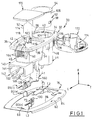
- the insulating body 32 has an upper plate horizontal mounting 34 delimited by upper faces 36 and lower 38, which has a circular opening 40 and a substantially rectangular opening 42 which extends respectively down by a tank 44 of the intake power and by a cavity 46 of an integrated lighting device, in accordance with the teachings of the invention, when taking power.
- the opening may take any other shape, and in particular circular.
- the plate or plate 34 is substantially shaped rectangular oriented in the longitudinal direction and, in the embodiments illustrated in the figures, the openings 40 and 42 are arranged adjacent in the longitudinal direction so as to have a very compact package.
- the tank 44 is in cylindrical pot shape with vertical axis A1 and is in particular delimited by a cylindrical skirt 48 and by a lower bottom horizontal 50.
- the cavity 46 of the lighting device which receives a lamp 52 is of overall shape rectangular parallelepiped delimited by a side wall peripheral 54 and by a horizontal bottom bottom 56.
- the upper plate 34 Under its lower face 38, the upper plate 34 has a peripheral shoulder 60, essentially around of the cavity 46 whose contour is complementary to that of a cutout 62 formed in a panel 64 of a part of the vehicle automobile and in which is mounted the socket 30 integrating the lamp 52.
- the insulating body 32 has two ribs 164 vertical and longitudinal orientation formed outside of the wall 54 and which are each delimited by a shoulder upper 66 extending below the lower face 38 to a distance which, as can be seen in figure 5, corresponds substantially to the thickness of the panel 64.
- the body 32 has a tab 68, elastically deformable which is molded with the side wall 48 of the tank 44 and which extends generally vertically towards the high with its upper free end 70 which delimits a notch or spout 72 located opposite the underside 38.
- this design allows easy mounting and economic of the socket 30 by introducing the edge of the cutout 62 on the side of the ribs 164, then tilting overall vertically from top to bottom to introduce tab 68 which is elastically deforms thanks to its external face forming a ramp which cooperates with the corresponding edge of the cutout until that its notch 72 comes to fit under the cutout.
- This method of attachment allows the disassembly of the socket 30 by elastically deforming the tab 68.
- the number and position of the ribs 164 and the legs 68 may vary depending on the applications, and in particular function of the efforts to be collected, the value of which is determined by the client's specifications which integrate the plug into a sign.
- the body 32 shown in Figures 1 to 6 also allows the mounting of socket 30 by means of the peripheral clip lower 76, in panels of different thicknesses, especially in the case of an externally coated panel a fabric or a covering carpet.
- the front transverse face of the side wall 54 of the tank 46 has a series of notches 78 formed between the ribs 164, while the rear longitudinal part of the side wall 48 of the tank 44 comprises, on either side of the elastic tab 68, similar notches 80.
- Clip 76 is a cut and folded sheet metal part that consists essentially of a peripheral flange 82 whose upper face 84 is planar and horizontal to come in support under the lower face 65 of the panel 64.
- the internal contour 86 of the collar 84 includes a front elastic lug 88 which extends opposite the notches 78 and two rear pins 90 which extend opposite the notches 80.
- the clip 76 can be used in combination with the snap-in mounting of tab 68, to avoid any accidental dismantling, or understood to be used when the thickness of the panel 64, delimited by its upper 63 and lower 65 faces, is more large or weaker, the leg 68 then no longer having fixing function, the latter being provided by the sole clip 76.
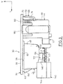
- the power take-off 30 essentially consists by the tank 44 which internally receives a tubular sleeve metallic 92 which internally doubles the cylindrical wall internal 94 of the skirt 48 at the top of the latter, the sleeve having at its upper end a flange horizontal 94 which is supported in a counterbore 96 of the opening 40 to position it in its assembled position in which it is immobilized by lugs 96 of the wall 94 received in notches 98 of the sleeve.
- the sleeve 92 is angularly oriented around the axis A1 compared to tank 44 thanks to a lug 100, coming from cut out with sleeve 92 near its lower edge 102 which projects radially outward and which is received in a groove 104 formed in the wall 94 which is open vertically upwards to allow the passage of the lug 100 when the sleeve 92 is placed in the tank 44.
- the rear part (at left) of the side wall 48 of the tank 44 has a slot vertical 106 opposite the side wall 54 of the cavity 46, which extends over part of the height and which constitutes a passage, allowing, as will be explained later, a electrical connection with the cylindrical external lateral face and conductor 108 of sleeve 92.
- the bottom 50 of the tank 44 has a central hole 110, laterally delimited by a tubular collar 112 of axis vertical which projects inside the tank 44, and in which is arranged a fixed contact pad P2 belonging to a blade conductor L2.
- the arrangement and positioning of the sleeve 92 and the P2 fixed stud are such that they allow their connection electric with complementary means of a male plug standardized (not shown in the figures).
- the sleeve 92 is in particular partly defined by the SAE J563 standard.
- the collar 112 makes it possible to prevent a metallic object falling into tank 44 does not establish a short circuit accidental between the sleeve 92 and the pad P2 thereby causing destruction of the fuse fitted to the electrical circuit vehicle correspondent.
- the lamp 52 is here, without limitation, of type W5W and it conventionally comprises a body or bulb 114 and a lower base 116 which has two contacts or terminals 118, 120 each of which is intended to be connected to a stud contact P1, P3, respectively, belonging to a socket 122 for mounting the base 116 of the lamp which is integrated into the bottom of cavity 46.
- the sleeve 122 thus comprises an insulating body 124 produced come of matter by molding with the bottom 56, below this last and it houses two pairs of fixed contact pads P1 and P3 each of which belongs respectively to a first blade of electrical connection L1 and a third electrical connection blade L3 (see Figure 1).
- each pair of studs P1, P3 is presented here in the form of a fork which, when the lamp 52 is in place, clamps the terminal 118, 120 corresponding.
- the invention is in no way limited to this type of lamp and at this conformation of the pads P1 and P3, the lamp can be of any type and in particular an LED, the pads P1, P3 of the socket 122 being of a design and shape adapted to the lamp base 116.
- the pads P1 and P3 are placed vertically from below up in the insulating body 124 of the socket 122 and they are there retained thanks to associated claws 128 and 130 respectively which are made integrally with the pads P1, P3 of the blades L1 and L2, by cutting and folding, and which are received in complementary slots of the insulating body 124 of the sleeve 122 thereby ensuring vertical retention in the position of blades L1 and L3.
- the second blade L2 is the power blade which connects the central fixed stud P2 to a pin B2 of the connector which is itself intended to be connected to the electrical circuit device of the vehicle.
- the blade L2 is cut and folded in a thick sheet and its two opposite front and rear longitudinal ends make up respectively the fixed central block P2 and the pin B2 of the common connector.
- the insulating body 142 of the connector 140 is here produced formed by molding with the insulating body 32 and it has a general rectangular parallelepiped shape horizontal orientation being located at the longitudinal end before under the cavity 46.
- the body 142 is delimited by a lateral side wall rectangular 144 and by a transverse and vertical rear bottom 146.
- the rear wall 146 has a clearance 148 in vertical and longitudinal slot shape for the passage of the spindle B2, the blade L2 being retained in position with its overall horizontal orientation thanks to a lug 150 which is resiliently fitted over a complementary shape 152 of the body of the sleeve 122, as well as by the socket of the rear free end constituting the fixed stud P2 in shapes 154 and 156 from the bottom 50 of the tank 44.
- the first conductive strip L1 ensures the connection at the negative pole of the vehicle's electrical circuit, i.e. at the mass, and it is cut and folded in a sheet of weaker thickness than that of blade L2 with its free end rear 160 which is folded vertically upwards and elastically deformable to come into contact support with the outer surface of sleeve 92, through slot 106, as this can be seen in Figure 5.
- the first blade L1 has a horizontal longitudinal pin B1 belonging to the connector 140.
- Pin B1 penetrates longitudinally into the body insulator 142 thanks to a clearance 162 provided for this purpose (see figure 1).
- the L1 blade is fixed in position by the claw 128, in the same way as the attachment of the third blade L3 which is provided by the claw 130.
- the design of the third L3 blade is analogous to that of the first blade L1, but it only ensures the connection of the stud 120 of the lamp 52 with a positive wire of the circuit comprising for this purpose a third pin B3 produced in one piece with the L3 blade and which penetrates the body of connector 140 in the same way as pin B1.
- the three pins B1, B2 and B3 have a longitudinal, horizontal orientation and are coplanar.
- the connector 140 with its insulating body 142 and its three pins is a common connector for the connection of the electrical power outlet 30 integrating a lamp 52, in accordance with the teachings of the invention, this common connector comprising a common pin B1 for the earth connection of the plug and the lamp.
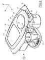
- the invention proposes, in the first three embodiments, to use an attached plug 172 which is here a soft material cabochon which has a body 174 capable of being received, in the closed position, inside the sleeve 92 (see FIG. 5), the body being slightly compressed elastically and being retained in the sleeve by friction.
- an attached plug 172 which is here a soft material cabochon which has a body 174 capable of being received, in the closed position, inside the sleeve 92 (see FIG. 5), the body being slightly compressed elastically and being retained in the sleeve by friction.
- the plug 172 is attached to the plate 34 by a tab articulation 176 comprising a fold 178 forming a hinge, the tab 176 being fitted into a notch 180 formed in the underside 38 of the plate 34 (see Figure 3) being there maintained by nesting complementary shapes, the mounting of tab 176 being "locked” when the product is in place in cutout 62 as far as it is trapped between the plate 34 and the part facing the upper face 63 of panel 64.
- Inscriptions for example of voltage and power, can be made by molding with the cabochon 172, or in the form of stickers affixed to the cabochon, or by paint depot, etc.
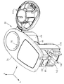
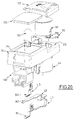
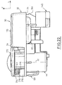
- the plug 172 can be produced in the form of a flap rigid mounted articulated on the plate 34 and which, in its position closed towards which it is spring-loaded by a spring torsion 210 arranged around its axis of articulation A3, extends in a horizontal plane flush with the face upper 36 of plate 34, in the same manner as the transparent plate 170 which closes the cavity 46 while improving thus the aesthetics of the whole and avoiding that the users do not forget to close the plug 172 after using the power take-off.
- the upper face 36 of the upper plate 34 has a clearance 212 which receives the articulated flap 172 in position closed.
- the spring 210 is mounted on a pivot 214 produced coming from material with the plate 32 and its vertical end strands 216 and horizontal (not visible in the figures) take respectively pressing on a rear facet 218 of the insulating body and in a housing under the internal face of the flap 172 to stress permanently the flap 172 in horizontal position closed in support on the upper face of clearance 212.
- the general axis of the lamp 52 and the cavity 46 which receives is a vertical axis A2 parallel to the axis A1 of the tank 44 of so that the luminous flux provided by the lamp 52 is globally directed vertically upwards considering the FIGS.
- the invention is not limited to this design, the lighting device which can have an axis A2 along a different orientation, forming an angle with respect to the axis A1 of the socket, for example horizontal.
- the assembly 30 can for example then be placed on the side of a rear shelf of the passenger compartment of the vehicle and be accessible to rear passengers while lighting the trunk.
- a switch 190 of general design known with a control button 192 on its face upper is mounted by elastic fitting in a complementary opening 194 formed in the upper plate 34, between the tank 44 and the cavity 42, the length of the plate being for this purpose greater than in the first mode of production.
- the body 196 of the switch extends vertically in below the plate 34 with its two terminals 198 and 200 which extend vertically in the space between the tank 44 and the cavity 42.
- the electrical connection blade L3 is made in two parallel sections L3G and L3D.
- the L3D section includes pin B3 and, at its end rear longitudinal, one leg bent in direction vertical 202 which has at its free end a pellet of contact 204 which, in the mounted position of switch 190, is in elastic support against terminal 200.
- the L3G section is generally similar in design to that of the blade L3 of the first embodiment, with the pair of poles P3 and the claw 130, while its end longitudinal rear extends by a vertical tab 206 and a contact pad 208 which, in the mounted position, is supported elastic against terminal 198.
- the assembly constituted by the two sections L3G and L3D and the switch 190 thus ensures electrical continuity between the poles P3 and terminal B3, which can be interrupted when switch 190 is open.
- the means for fixing the socket 30 are here simplified, that is, they only have the ribs 164 and the tab 68 in the absence of the system constituted by the clip 76 and the notches 78 and 80 provided in the first embodiment.
- the body 142 is a part molded from material insulating plastic independently of the body 32, with shapes broadly analogous to those of the first two modes of production.
- the body insulator has two vertical arms 220 and 222 which extend the along the longitudinal faces of the side wall 54 of the cavity, vertically below the latter, with faces internal facing 224 and 226 vertical orientation and longitudinal which are designed to receive the faces between them corresponding 228 and 230 of the body 142, the arms 220 and 222 thus being received vertically in two vertical slides formed in the body 142.
- Each slide is thus formed by the face 228, 230 associated with two vertical ribs 229, 231.
- the fixing in the vertical direction of the body 142 is ensured by two nozzles or hooks 232 and 234 which, in position body mounted 142, are received under the lower faces 236 and 238 of horizontal orientation of the body 142 (see FIG. 15, 16, 18 and 19).
- the upper face 145 of the horizontal partition upper 144 of the insulating body 142 of the connector 140 comprises three longitudinal grooves R1 to R3 which receive the arms horizontal top belonging to three metal jumpers CA1, CA2 and CA3 including the longitudinal lower arms constitute pins B1, B2 and B3 respectively.
- the three riders are mounted in the body 142 of so that the three pins B1, B2 and B3 protrude at the interior of the insulating body by crossing slits formed in the rear transverse bulkhead 146 thereof.
- the body 142 can be molded around the three jumpers CA1 to CA3.
- the free upper faces 240, 242 and 244 of the arms of the three jumpers CA1 to CA3 constitute contact surfaces for connecting each jumper with the associated link blade L1 to L3 whose end front longitudinal is shaped for this purpose.
- the blades L1 to L3 are standardized components with power take-off 30 for constitute a common component, only the connector 140 with its jumpers CA1 to CA3 can be of shapes and different dimensions depending on the model.
- the three blades L1 to L3 thus each have an arm horizontal 241, 243 and 245 which are coplanar, the contacts being established by slight elastic deformation, vertically towards the top, legs 241, 243 and 245 when the body 142 is in resiliently fitted position between the arms 220 and 222.
Landscapes
- Connector Housings Or Holding Contact Members (AREA)
- Non-Portable Lighting Devices Or Systems Thereof (AREA)
- Liquid Crystal (AREA)
- Lighting Device Outwards From Vehicle And Optical Signal (AREA)
- Details Of Connecting Devices For Male And Female Coupling (AREA)
- Arrangement Of Elements, Cooling, Sealing, Or The Like Of Lighting Devices (AREA)
- Connecting Device With Holders (AREA)
Abstract
Description
- la cuve du corps isolant est doublée intérieurement par un manchon de contact fixe et porte une première lame conductrice qui relie le manchon à une première broche d'un connecteur ;
- le corps isolant porte un plot de contact fixe agencé au centre de la cuve et une deuxième lame conductrice qui relie le plot central de contact à une deuxième broche d'un connecteur ;
- le fond de la cavité comporte une douille à deux pôles opposés qui reçoit le culot de la lampe ;
- le corps isolant porte deux lames conductrices qui relient les deux pôles de la douille à deux broches d'un connecteur ;
- la prise électrique comporte un connecteur commun pour le raccordement de la prise et de la lampe ;
- le connecteur commun est un connecteur à trois broches, la première lame conductrice relie l'un des pôles de la douille à la première broche du connecteur commun, et le corps isolant porte une troisième lame conductrice qui relie l'autre pôle de la douille de la lampe à une troisième broche du connecteur commun ;
- les broches du connecteur commun sont portées par un support isolant réalisé en une seule pièce avec le corps isolant ;
- les broches du connecteur commun sont portées par un support isolant rapporté sur le corps isolant ;
- chaque broche de connecteur est constituée par une extrémité libre de la lame conductrice associée ;
- chaque broche de connecteur est portée par le support isolant rapporté du connecteur commun et est reliée électriquement à une patte de la lame conductrice associée ;
- le corps isolant est une pièce moulée en matière plastique qui intègre la cuve et la cavité ;
- le corps isolant comporte des moyens de positionnement et de fixation des lames conductrices ;
- le corps isolant comporte une plaque supérieure horizontale de montage de la prise dans laquelle débouche la cuve ;
- la cavité comporte une face ouverte, opposée audit fond, par laquelle sort le flux lumineux de la lampe ;
- la face ouverte de la cavité débouche dans la plaque de montage du corps isolant ;
- la prise électrique comporte un interrupteur intégré de commande de la lampe ;
- la troisième lame est réalisée en deux tronçons entre lesquels est interposé l'interrupteur ;
- la prise électrique comporte un bouchon articulé de fermeture de la cuve ;
- le bouchon est un volet articulé de fermeture, rappelé élastiquement en position fermée dans laquelle il s'étend sensiblement dans le plan de la plaque supérieure de montage.
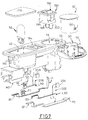
- la figure 1 est une vue en perspective des différents composants d'un premier mode de réalisation d'une prise de puissance intégrant un dispositif d'éclairage conformément aux enseignements de l'invention ;
- la figure 2 est une vue en perspective de la prise de la figure 1 qui est représentée avec ses composants assemblés et son bouchon de prise en position ouverte ;
- la figure 3 est une vue latérale selon la flèche F3 de la figure 2, sans le bouchon ;
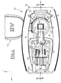
- la figure 4 est une vue de dessous de la prise représentée à la figure 2 ;
- la figure 5 est une vue en coupe longitudinale, selon la ligne 5-5 de la figure 4 avec le bouchon en position fermée, et sur laquelle la prise est représentée en position montée dans un panneau du véhicule ;
- la figure 6 est une vue en section transversale selon la ligne 6-6 de la figure 5 ;
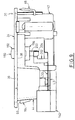
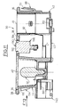
- les figures 7 à 11 sont des vues similaires à celles des figures 1 à 5 qui illustrent un deuxième mode de réalisation d'une prise selon l'invention qui intègre un interrupteur de commande du dispositif d'éclairage ;
- la figure 12 est une vue longitudinale en bout selon la flèche F12 de la figure 11 ;
- les figures 13 à 18 sont des vues similaires à celles des figures 1 à 6 qui illustrent un troisième mode de réalisation d'une prise électrique de puissance selon l'invention avec une conception modulaire du connecteur commun ;
- la figure 19 est une vue longitudinale en bout selon la flèche F19 de la figure 17 ; et
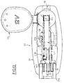
- les figures 20 à 22 sont des vues similaires à celles des figures 1 à 3 qui illustrent une variante de réalisation du bouchon de fermeture de la cuve de la prise de puissance.
Claims (17)
- Prise électrique de puissance (30), notamment pour le raccordement au circuit électrique d'un véhicule automobile d'un appareil ou d'un accessoire comportant une fiche mâle complémentaire de la prise, du type comportant un corps (32) en matériau isolant qui comporte une cuve cylindrique (44) d'axe (A1) vertical, susceptible de recevoir le corps complémentaire de la fiche mâle, et qui porte des moyens (92, P2, L2, L1) de raccordement électrique de la prise à un circuit électrique de puissance du véhicule, caractérisée en ce que le corps isolant (32) comporte une cavité (46) pour une lampe (52) d'éclairage, notamment pour un éclairage puissant d'une zone du véhicule, et porte des moyens (P1, L1, P3, L3) de raccordement électrique de la lampe (52) à un circuit électrique du véhicule.
- Prise électrique selon la revendication précédente, caractérisée :en ce que la cuve (44) du corps isolant est doublée intérieurement par un manchon (92) de contact fixe et porte une première lame conductrice (L1) qui relie le manchon (92) à une première broche (B1) d'un connecteur (140) ;en ce que le corps isolant (32, 44) porte un plot de contact fixe agencé au centre de la cuve (44) et une deuxième lame conductrice (L2) qui relie le plot central de contact (P2) à une deuxième broche (B2) d'un connecteur ;en ce que le fond (56) de la cavité (46) comporte une douille (122) à deux pôles opposés (P1, P3) qui reçoit le culot (116) de la lampe (52) ;et en ce que le corps isolant porte deux lames conductrices (L1, L3) qui relient les deux pôles (P1, P3) de la douille (122) à deux broches (B1, B3) d'un connecteur (140).
- Prise électrique selon la revendication précédente, caractérisée en ce qu'elle comporte un connecteur (140, B1, B2, B3) commun pour le raccordement de la prise (30) et de la lampe (52).
- Prise électrique selon la revendication précédente, caractérisée en ce que :le connecteur commun (140) est un connecteur à trois broches (B1, B2, B3) ;la première lame conductrice (L1) relie l'un des pôles (P1) de la douille (122) à la première broche (B1) du connecteur commun ;et le corps isolant porte une troisième lame (L3) conductrice qui relie l'autre pôle (P3) de la douille de la lampe (52) à une troisième broche du connecteur commun.
- Prise électrique selon l'une des revendications 3 ou 4, caractérisée en ce que les broches (B1, B2, B3) du connecteur (140) commun sont portées par un support isolant (142) réalisé en une seule pièce avec le corps isolant (32).
- Prise électrique selon l'une des revendications 3 ou 4, caractérisée en ce que les broches (B1-CA1, B2-CA2, B3-CA3) du connecteur (140) commun sont portées par un support isolant (142) rapporté sur le corps isolant (32, 220, 222).
- Prise électrique selon l'une quelconque des revendications 2 à 6, caractérisée en ce que chaque broche de connecteur (B1, B2, B3) est constituée par une extrémité libre de la lame conductrice (L1, L2, L3) associée.
- Prise électrique selon la revendication 5, caractérisée en ce que chaque broche (B1-CA1, B2-CA2, B3-CA3) de connecteur est portée par le support isolant (142) rapporté du connecteur commun et est reliée électriquement à une patte (241, 243, 245) de la lame conductrice (L1, L2, L3) associée.
- Prise électrique selon l'une quelconque des revendications 2 à 8, caractérisée en ce que le corps isolant (32) est une pièce moulée en matière plastique qui intègre la cuve (44) et la cavité (46).
- Prise électrique selon la revendication précédente, caractérisée en ce que le corps isolant (32) comporte des moyens de positionnement et de fixation des lames conductrices (L1, L2, L3).
- Prise électrique selon l'une quelconque des revendications 9 ou 10, caractérisée en ce que le corps isolant (32) comporte une plaque supérieure horizontale (34) de montage de la prise (30) dans laquelle débouche la cuve (40, 44).
- Prise électrique selon l'une quelconque des revendications 9 à 11, caractérisée en ce que la cavité comporte (46) une face ouverte(42), opposée audit fond (56), par laquelle sort le flux lumineux de la lampe (52).
- Prise électrique selon la revendication précédente prise en combinaison avec la revendication 11, caractérisée en ce que la face ouverte (42) de la cavité (46) débouche dans la plaque de montage (34) du corps isolant (32).
- Prise électrique selon l'une quelconque des revendications précédentes, caractérisée en ce qu'elle comporte un interrupteur intégré (190) de commande de la lampe (52).
- Prise électrique selon la revendication précédente prise en combinaison avec la revendication 4, caractérisée en ce que la troisième lame (L3) est réalisée en deux tronçons (L3G, L3D) entre lesquels est interposé l'interrupteur (190).
- Prise électrique selon l'une quelconque des revendications précédentes, caractérisée en ce qu'elle comporte un bouchon articulé (172) de fermeture de la cuve (44, 92).
- Prise électrique selon la revendication précédente, prise en combinaison avec la revendication 11, caractérisée en ce que le bouchon est un volet articulé de fermeture, rappelé élastiquement en position fermée dans laquelle il s'étend sensiblement dans le plan de la plaque supérieure de montage.
Applications Claiming Priority (2)
| Application Number | Priority Date | Filing Date | Title |
|---|---|---|---|
| FR0104216 | 2001-03-27 | ||
| FR0104216A FR2823023B1 (fr) | 2001-03-27 | 2001-03-27 | Prise de puissance avec eclaireur d'interieur vehicule integre |
Publications (2)
| Publication Number | Publication Date |
|---|---|
| EP1248330A1 true EP1248330A1 (fr) | 2002-10-09 |
| EP1248330B1 EP1248330B1 (fr) | 2012-02-01 |
Family
ID=8861665
Family Applications (1)
| Application Number | Title | Priority Date | Filing Date |
|---|---|---|---|
| EP02290715A Expired - Lifetime EP1248330B1 (fr) | 2001-03-27 | 2002-03-21 | Prise électrique de puissance de véhicule automobile comportant un dispositif intégré d'éclairage |
Country Status (5)
| Country | Link |
|---|---|
| US (1) | US6796832B2 (fr) |
| EP (1) | EP1248330B1 (fr) |
| JP (1) | JP2002313508A (fr) |
| AT (1) | ATE544204T1 (fr) |
| FR (1) | FR2823023B1 (fr) |
Families Citing this family (2)
| Publication number | Priority date | Publication date | Assignee | Title |
|---|---|---|---|---|
| JP2005148296A (ja) * | 2003-11-13 | 2005-06-09 | Olympus Corp | 顕微鏡の光源装置 |
| US20240198934A1 (en) * | 2022-12-20 | 2024-06-20 | Nomadyn Inc. | Replacement Vehicle Body Panel with Integral Accessory Mounts |
Citations (4)
| Publication number | Priority date | Publication date | Assignee | Title |
|---|---|---|---|---|
| US5007863A (en) * | 1990-09-17 | 1991-04-16 | Jialuo Xuan | Module-type multi-function electrical power adapter for automobiles and the like |
| DE4041886A1 (de) * | 1990-12-27 | 1992-07-02 | Schoeller & Co Elektrotech | Kfz-steckdose |
| JPH0785934A (ja) * | 1993-09-20 | 1995-03-31 | Stanley Electric Co Ltd | カプラ直結型バルブソケット |
| EP1033791A2 (fr) * | 1999-03-02 | 2000-09-06 | Osram Sylvania Inc. | Douille de lampe coudée |
Family Cites Families (6)
| Publication number | Priority date | Publication date | Assignee | Title |
|---|---|---|---|---|
| US1314218A (en) * | 1919-08-26 | Manuel b | ||
| US1274552A (en) * | 1916-02-21 | 1918-08-06 | Nat Metal Molding Company | Electrical fitting. |
| US1634404A (en) * | 1921-04-04 | 1927-07-05 | Harry A Douglas | Circuit-continuing device |
| US1722886A (en) * | 1928-03-16 | 1929-07-30 | Beck James Earl | Illuminated ornamental device for decorative purposes |
| US2684470A (en) * | 1952-04-16 | 1954-07-20 | Pierce John B Foundation | Electrical fixture for flat twin electrical conductors |
| US5536175A (en) * | 1994-09-29 | 1996-07-16 | Cooper Industries, Inc. | Backplate assembly and method of making same |
-
2001
- 2001-03-27 FR FR0104216A patent/FR2823023B1/fr not_active Expired - Lifetime
-
2002
- 2002-03-21 AT AT02290715T patent/ATE544204T1/de active
- 2002-03-21 EP EP02290715A patent/EP1248330B1/fr not_active Expired - Lifetime
- 2002-03-27 JP JP2002089314A patent/JP2002313508A/ja active Pending
- 2002-03-27 US US10/109,229 patent/US6796832B2/en not_active Expired - Lifetime
Patent Citations (4)
| Publication number | Priority date | Publication date | Assignee | Title |
|---|---|---|---|---|
| US5007863A (en) * | 1990-09-17 | 1991-04-16 | Jialuo Xuan | Module-type multi-function electrical power adapter for automobiles and the like |
| DE4041886A1 (de) * | 1990-12-27 | 1992-07-02 | Schoeller & Co Elektrotech | Kfz-steckdose |
| JPH0785934A (ja) * | 1993-09-20 | 1995-03-31 | Stanley Electric Co Ltd | カプラ直結型バルブソケット |
| EP1033791A2 (fr) * | 1999-03-02 | 2000-09-06 | Osram Sylvania Inc. | Douille de lampe coudée |
Non-Patent Citations (1)
| Title |
|---|
| PATENT ABSTRACTS OF JAPAN vol. 1995, no. 06 31 July 1995 (1995-07-31) * |
Also Published As
| Publication number | Publication date |
|---|---|
| ATE544204T1 (de) | 2012-02-15 |
| FR2823023B1 (fr) | 2003-05-16 |
| US20020197909A1 (en) | 2002-12-26 |
| FR2823023A1 (fr) | 2002-10-04 |
| US6796832B2 (en) | 2004-09-28 |
| EP1248330B1 (fr) | 2012-02-01 |
| JP2002313508A (ja) | 2002-10-25 |
Similar Documents
| Publication | Publication Date | Title |
|---|---|---|
| EP2859631A1 (fr) | Plaque de finition equipee de moyens de centrage sur un element interne d'un appareillage electrique | |
| EP0505256A2 (fr) | Adaptateur en deux parties pour appareil électrique à brancher par une fiche sur un socle de prise de courant | |
| EP0813663B1 (fr) | Dispositif de raccordement d'angle pour conduit a corps en gouttiere et couvercle tel que moulure, plinthe ou goulotte, notamment pour appareillage electrique | |
| EP1248330B1 (fr) | Prise électrique de puissance de véhicule automobile comportant un dispositif intégré d'éclairage | |
| FR2738957A1 (fr) | Connecteur electrique | |
| FR2698492A1 (fr) | Bloc intégré à câble et plaque à bornes. | |
| FR2738676A1 (fr) | Appareil electrique a bornes de raccordement protegees par un diaphragme | |
| FR2503466A1 (fr) | Structure de connecteur a plusieurs contacts pour le branchement de remorques ou vehicules similaires | |
| FR2728208A1 (fr) | Projecteur de vehicule | |
| EP0820119B1 (fr) | Installation d'alimentation de dispositifs électriques sur des pavillons de véhicules | |
| FR2835595A1 (fr) | Douille de lampe pour projecteur de vehicule automobile, et reflecteur de projecteur destine a recevoir une telle douille de lampe. | |
| EP0669695B1 (fr) | Ensemble perfectionné d'alimentation et de commande, pour un alternateur de véhicule automobile | |
| EP0547929B1 (fr) | Prise de courant, notamment pour véhicule automobile | |
| EP1334877B1 (fr) | Kit de branchement de téléphone sur un véhicule | |
| FR2699744A1 (fr) | Groupe boîte à bornes-câbles, en particulier pour l'alimentation électrique d'appareils électroménagers. | |
| EP0669696B1 (fr) | Ensemble modulaire d'alimentation et de commande pour un alternateur de véhicule automobile | |
| FR2636278A1 (fr) | Structure de bras de siege a positions multiples particulierement adaptee pour le conducteur de vehicule automobile | |
| FR2823914A1 (fr) | Dispositif de blindage electromagnetique pour connecteur electrique | |
| FR2748977A1 (fr) | Motoreducteur pour essuie-glace et organe de connexion associe | |
| WO2011131894A1 (fr) | Douille a double verrouillage pour ampoule electrique | |
| FR2948237A1 (fr) | Douille pour lampe electrique avec un volet de securite | |
| FR2768861A1 (fr) | Boitier a piles pour jouet, et jouet equipe d'un tel boitier | |
| FR2776050A1 (fr) | Projecteur notamment pour vehicule automobile comportant un porte-lampe a connexion simplifiee | |
| FR3159119A1 (fr) | Ensemble comportant un cordon de recharge et un socle support pour le cordon de recharge | |
| FR2812978A1 (fr) | Douille automatique a doubles contacts |
Legal Events
| Date | Code | Title | Description |
|---|---|---|---|
| PUAI | Public reference made under article 153(3) epc to a published international application that has entered the european phase |
Free format text: ORIGINAL CODE: 0009012 |
|
| AK | Designated contracting states |
Kind code of ref document: A1 Designated state(s): AT BE CH CY DE DK ES FI FR GB GR IE IT LI LU MC NL PT SE TR |
|
| AX | Request for extension of the european patent |
Free format text: AL;LT;LV;MK;RO;SI |
|
| 17P | Request for examination filed |
Effective date: 20030326 |
|
| AKX | Designation fees paid |
Designated state(s): AT BE CH CY DE DK ES FI FR GB GR IE IT LI LU MC NL PT SE TR |
|
| 17Q | First examination report despatched |
Effective date: 20090820 |
|
| GRAP | Despatch of communication of intention to grant a patent |
Free format text: ORIGINAL CODE: EPIDOSNIGR1 |
|
| RIN1 | Information on inventor provided before grant (corrected) |
Inventor name: LAU, MICHEL,C/O VALEO VISION Inventor name: ANDRIEU, MICHEL,C/O VALEO VISION Inventor name: ROSTAN, PHILIPPE,C/O VALEO VISION |
|
| GRAS | Grant fee paid |
Free format text: ORIGINAL CODE: EPIDOSNIGR3 |
|
| GRAA | (expected) grant |
Free format text: ORIGINAL CODE: 0009210 |
|
| AK | Designated contracting states |
Kind code of ref document: B1 Designated state(s): AT BE CH CY DE DK ES FI FR GB GR IE IT LI LU MC NL PT SE TR |
|
| REG | Reference to a national code |
Ref country code: GB Ref legal event code: FG4D Free format text: NOT ENGLISH |
|
| REG | Reference to a national code |
Ref country code: CH Ref legal event code: EP Ref country code: AT Ref legal event code: REF Ref document number: 544204 Country of ref document: AT Kind code of ref document: T Effective date: 20120215 |
|
| REG | Reference to a national code |
Ref country code: DE Ref legal event code: R096 Ref document number: 60242126 Country of ref document: DE Effective date: 20120405 |
|
| REG | Reference to a national code |
Ref country code: NL Ref legal event code: VDEP Effective date: 20120201 |
|
| PGFP | Annual fee paid to national office [announced via postgrant information from national office to epo] |
Ref country code: DE Payment date: 20120315 Year of fee payment: 11 |
|
| PGFP | Annual fee paid to national office [announced via postgrant information from national office to epo] |
Ref country code: BE Payment date: 20120329 Year of fee payment: 11 Ref country code: GB Payment date: 20120320 Year of fee payment: 11 |
|
| PG25 | Lapsed in a contracting state [announced via postgrant information from national office to epo] |
Ref country code: NL Free format text: LAPSE BECAUSE OF FAILURE TO SUBMIT A TRANSLATION OF THE DESCRIPTION OR TO PAY THE FEE WITHIN THE PRESCRIBED TIME-LIMIT Effective date: 20120201 |
|
| REG | Reference to a national code |
Ref country code: IE Ref legal event code: FD4D |
|
| PG25 | Lapsed in a contracting state [announced via postgrant information from national office to epo] |
Ref country code: FI Free format text: LAPSE BECAUSE OF FAILURE TO SUBMIT A TRANSLATION OF THE DESCRIPTION OR TO PAY THE FEE WITHIN THE PRESCRIBED TIME-LIMIT Effective date: 20120201 Ref country code: PT Free format text: LAPSE BECAUSE OF FAILURE TO SUBMIT A TRANSLATION OF THE DESCRIPTION OR TO PAY THE FEE WITHIN THE PRESCRIBED TIME-LIMIT Effective date: 20120601 Ref country code: GR Free format text: LAPSE BECAUSE OF FAILURE TO SUBMIT A TRANSLATION OF THE DESCRIPTION OR TO PAY THE FEE WITHIN THE PRESCRIBED TIME-LIMIT Effective date: 20120502 |
|
| REG | Reference to a national code |
Ref country code: AT Ref legal event code: MK05 Ref document number: 544204 Country of ref document: AT Kind code of ref document: T Effective date: 20120201 |
|
| PG25 | Lapsed in a contracting state [announced via postgrant information from national office to epo] |
Ref country code: CY Free format text: LAPSE BECAUSE OF FAILURE TO SUBMIT A TRANSLATION OF THE DESCRIPTION OR TO PAY THE FEE WITHIN THE PRESCRIBED TIME-LIMIT Effective date: 20120201 |
|
| PG25 | Lapsed in a contracting state [announced via postgrant information from national office to epo] |
Ref country code: MC Free format text: LAPSE BECAUSE OF NON-PAYMENT OF DUE FEES Effective date: 20120331 Ref country code: DK Free format text: LAPSE BECAUSE OF FAILURE TO SUBMIT A TRANSLATION OF THE DESCRIPTION OR TO PAY THE FEE WITHIN THE PRESCRIBED TIME-LIMIT Effective date: 20120201 Ref country code: IE Free format text: LAPSE BECAUSE OF FAILURE TO SUBMIT A TRANSLATION OF THE DESCRIPTION OR TO PAY THE FEE WITHIN THE PRESCRIBED TIME-LIMIT Effective date: 20120201 Ref country code: SE Free format text: LAPSE BECAUSE OF FAILURE TO SUBMIT A TRANSLATION OF THE DESCRIPTION OR TO PAY THE FEE WITHIN THE PRESCRIBED TIME-LIMIT Effective date: 20120201 |
|
| REG | Reference to a national code |
Ref country code: CH Ref legal event code: PL |
|
| PG25 | Lapsed in a contracting state [announced via postgrant information from national office to epo] |
Ref country code: IT Free format text: LAPSE BECAUSE OF FAILURE TO SUBMIT A TRANSLATION OF THE DESCRIPTION OR TO PAY THE FEE WITHIN THE PRESCRIBED TIME-LIMIT Effective date: 20120201 |
|
| PLBE | No opposition filed within time limit |
Free format text: ORIGINAL CODE: 0009261 |
|
| STAA | Information on the status of an ep patent application or granted ep patent |
Free format text: STATUS: NO OPPOSITION FILED WITHIN TIME LIMIT |
|
| 26N | No opposition filed |
Effective date: 20121105 |
|
| PG25 | Lapsed in a contracting state [announced via postgrant information from national office to epo] |
Ref country code: CH Free format text: LAPSE BECAUSE OF NON-PAYMENT OF DUE FEES Effective date: 20120331 Ref country code: LI Free format text: LAPSE BECAUSE OF NON-PAYMENT OF DUE FEES Effective date: 20120331 |
|
| REG | Reference to a national code |
Ref country code: DE Ref legal event code: R097 Ref document number: 60242126 Country of ref document: DE Effective date: 20121105 |
|
| PGFP | Annual fee paid to national office [announced via postgrant information from national office to epo] |
Ref country code: AT Payment date: 20120223 Year of fee payment: 11 |
|
| PG25 | Lapsed in a contracting state [announced via postgrant information from national office to epo] |
Ref country code: ES Free format text: LAPSE BECAUSE OF FAILURE TO SUBMIT A TRANSLATION OF THE DESCRIPTION OR TO PAY THE FEE WITHIN THE PRESCRIBED TIME-LIMIT Effective date: 20120512 |
|
| PGFP | Annual fee paid to national office [announced via postgrant information from national office to epo] |
Ref country code: ES Payment date: 20120323 Year of fee payment: 11 |
|
| BERE | Be: lapsed |
Owner name: VALEO VISION Effective date: 20130331 |
|
| GBPC | Gb: european patent ceased through non-payment of renewal fee |
Effective date: 20130321 |
|
| REG | Reference to a national code |
Ref country code: DE Ref legal event code: R119 Ref document number: 60242126 Country of ref document: DE Effective date: 20131001 |
|
| PG25 | Lapsed in a contracting state [announced via postgrant information from national office to epo] |
Ref country code: DE Free format text: LAPSE BECAUSE OF NON-PAYMENT OF DUE FEES Effective date: 20131001 Ref country code: GB Free format text: LAPSE BECAUSE OF NON-PAYMENT OF DUE FEES Effective date: 20130321 Ref country code: BE Free format text: LAPSE BECAUSE OF NON-PAYMENT OF DUE FEES Effective date: 20130331 |
|
| PG25 | Lapsed in a contracting state [announced via postgrant information from national office to epo] |
Ref country code: TR Free format text: LAPSE BECAUSE OF FAILURE TO SUBMIT A TRANSLATION OF THE DESCRIPTION OR TO PAY THE FEE WITHIN THE PRESCRIBED TIME-LIMIT Effective date: 20120201 |
|
| PG25 | Lapsed in a contracting state [announced via postgrant information from national office to epo] |
Ref country code: LU Free format text: LAPSE BECAUSE OF NON-PAYMENT OF DUE FEES Effective date: 20120321 |
|
| REG | Reference to a national code |
Ref country code: FR Ref legal event code: PLFP Year of fee payment: 15 |
|
| PG25 | Lapsed in a contracting state [announced via postgrant information from national office to epo] |
Ref country code: AT Free format text: THE PATENT HAS BEEN ANNULLED BY A DECISION OF A NATIONAL AUTHORITY Effective date: 20120201 |
|
| REG | Reference to a national code |
Ref country code: FR Ref legal event code: PLFP Year of fee payment: 16 |
|
| REG | Reference to a national code |
Ref country code: FR Ref legal event code: PLFP Year of fee payment: 17 |
|
| PGFP | Annual fee paid to national office [announced via postgrant information from national office to epo] |
Ref country code: FR Payment date: 20180329 Year of fee payment: 17 |
|
| PG25 | Lapsed in a contracting state [announced via postgrant information from national office to epo] |
Ref country code: FR Free format text: LAPSE BECAUSE OF NON-PAYMENT OF DUE FEES Effective date: 20190331 |