EP1248277B1 - Electromagnetic tripdevice having an elastically socket mounted electromagnetic circuit and an electromagnetic tripdevice having a floating coil - Google Patents
Electromagnetic tripdevice having an elastically socket mounted electromagnetic circuit and an electromagnetic tripdevice having a floating coil Download PDFInfo
- Publication number
- EP1248277B1 EP1248277B1 EP02290798A EP02290798A EP1248277B1 EP 1248277 B1 EP1248277 B1 EP 1248277B1 EP 02290798 A EP02290798 A EP 02290798A EP 02290798 A EP02290798 A EP 02290798A EP 1248277 B1 EP1248277 B1 EP 1248277B1
- Authority
- EP
- European Patent Office
- Prior art keywords
- release device
- electromagnetic
- electromagnetic release
- fixed core
- support
- Prior art date
- Legal status (The legal status is an assumption and is not a legal conclusion. Google has not performed a legal analysis and makes no representation as to the accuracy of the status listed.)
- Expired - Fee Related
Links
Images


Classifications
-
- H—ELECTRICITY
- H01—ELECTRIC ELEMENTS
- H01H—ELECTRIC SWITCHES; RELAYS; SELECTORS; EMERGENCY PROTECTIVE DEVICES
- H01H71/00—Details of the protective switches or relays covered by groups H01H73/00 - H01H83/00
- H01H71/10—Operating or release mechanisms
- H01H71/12—Automatic release mechanisms with or without manual release
- H01H71/24—Electromagnetic mechanisms
- H01H71/32—Electromagnetic mechanisms having permanently magnetised part
- H01H71/325—Housings, assembly or disposition of different elements in the housing
-
- H—ELECTRICITY
- H01—ELECTRIC ELEMENTS
- H01H—ELECTRIC SWITCHES; RELAYS; SELECTORS; EMERGENCY PROTECTIVE DEVICES
- H01H71/00—Details of the protective switches or relays covered by groups H01H73/00 - H01H83/00
- H01H71/02—Housings; Casings; Bases; Mountings
- H01H71/0207—Mounting or assembling the different parts of the circuit breaker
- H01H71/0214—Housing or casing lateral walls containing guiding grooves or special mounting facilities
-
- H—ELECTRICITY
- H01—ELECTRIC ELEMENTS
- H01H—ELECTRIC SWITCHES; RELAYS; SELECTORS; EMERGENCY PROTECTIVE DEVICES
- H01H71/00—Details of the protective switches or relays covered by groups H01H73/00 - H01H83/00
- H01H71/02—Housings; Casings; Bases; Mountings
- H01H71/025—Constructional details of housings or casings not concerning the mounting or assembly of the different internal parts
-
- H—ELECTRICITY
- H01—ELECTRIC ELEMENTS
- H01H—ELECTRIC SWITCHES; RELAYS; SELECTORS; EMERGENCY PROTECTIVE DEVICES
- H01H71/00—Details of the protective switches or relays covered by groups H01H73/00 - H01H83/00
- H01H71/10—Operating or release mechanisms
- H01H71/12—Automatic release mechanisms with or without manual release
- H01H71/24—Electromagnetic mechanisms
- H01H71/32—Electromagnetic mechanisms having permanently magnetised part
- H01H71/321—Electromagnetic mechanisms having permanently magnetised part characterised by the magnetic circuit or active magnetic elements
- H01H71/323—Electromagnetic mechanisms having permanently magnetised part characterised by the magnetic circuit or active magnetic elements with rotatable armature
-
- H—ELECTRICITY
- H01—ELECTRIC ELEMENTS
- H01H—ELECTRIC SWITCHES; RELAYS; SELECTORS; EMERGENCY PROTECTIVE DEVICES
- H01H71/00—Details of the protective switches or relays covered by groups H01H73/00 - H01H83/00
- H01H71/10—Operating or release mechanisms
- H01H71/12—Automatic release mechanisms with or without manual release
- H01H71/24—Electromagnetic mechanisms
- H01H71/32—Electromagnetic mechanisms having permanently magnetised part
- H01H71/327—Manufacturing or calibrating methods, e.g. air gap treatments
Definitions
- the invention relates to an electromagnetic actuator comprising, in a housing comprising a base covered by a cover, an electromagnetic circuit comprising a fixed armature resting on the base, and a movable armature capable of opening and closing the electromagnetic circuit, said fixed armature being taken between the base and the cover.
- This type of trigger including the mounting it provides has a number of disadvantages.
- the application of the fixed armature against the base is likely to cause in the latter stresses and uncontrolled deformations that can cause a bad positioning of the fixed armature, which affects the proper operation of the trigger.
- An object of the present invention is to solve in particular the aforementioned drawbacks by proposing an electromagnetic release which, while being of simple design, has a reliable, precise, durable operation.
- the invention proposes an electromagnetic trigger as presented in the introduction, characterized in that the base comprises an elastically deformable zone, capable of sinking under the pressure of the fixed armature, the dimensions and the conformation of the base, the cover and the armature being able to allow the clamping of the armature between the cover and said deformable zone which solicits it towards the cover under the effect of its own elasticity.
- the pin occupies a median position in said deformable zone, which allows a substantially uniform distribution of the stresses in the deformable zone.
- the carcass of the coil being secured to the fixed armature, it is likely to transmit its own stresses and deformations, especially during the assembly of the trigger, when welding the son of the coil on its pins, or again during the installation of the trigger, during which the pins intervene.
- the fixed armature is thus likely to be veiled or folded, which can affect the air gap between the armatures and, in any case, is detrimental to the proper functioning of the trigger.
- a further object of the present invention is to solve in particular the disadvantages which have just been exposed, by proposing an electromagnetic release whose design allows at least to limit the impact of external constraints on the fixed armature.
- the invention provides an electromagnetic trip device comprising, in a housing comprising a pedestal capped with a cover, an electromagnetic circuit comprising a fixed armature resting on the base, and a movable armature capable to open and close the electromagnetic circuit, said fixed armature being taken between the base and the cover, the trigger further comprising a coil comprising a carcass on which is wound a winding, said carcass being threaded on the fixed and integral armature housing, characterized in that the carcass is rigidly mounted relative to the housing and floating relative to the fixed armature.
- the trigger is thus more reliable, more durable, and in a sustainable way.
- FIGS. 1 to 3 show an electromagnetic trigger 1 with high sensitivity for a switch or a circuit breaker, which comprises, in a case 2 supposedly fixed, composed of a base 3 capped with a cover 4, an electromagnetic circuit 5 comprising a U-shaped fixed armature 6, secured to the casing 2, and a movable armature 7 called a pallet, pivotable to open or close the electromagnetic circuit 5.
- the trigger 1 is described with respect to this marker, according to the orientation adopted in FIG. 2, which corresponds to the most common use of the trigger 1.
- the fixed armature 6 and the pallet 7 are both made of a ferromagnetic material, such as an iron-nickel alloy.
- the fixed armature 6 comprises a first branch 8 called before and a second branch 9 said rear, connected by a base 10 resting on the base 3 of the housing 2.
- the electromagnetic circuit 5 comprises a coil 11 comprising a carcass 12 on which is wound a winding 13, the carcass 12 being threaded onto the front branch 8 of the fixed armature 6 and integral with the base 3.
- the magnet 14 for the magnetic polarization of the fixed armature 6.
- the magnet 14, of parallelepipedal shape, is fixed by one of its ends on the base 10 of the fixed armature 6, preferably by welding. More specifically, the magnet 14 is fixed on an upper face 15 of the base 10, which also has an opposite lower face 16.
- the pallet 7 is capable of occupying at least two positions of stable equilibrium, namely a working or engaged position, in which it is pressed against the branches 8, 9 of the fixed armature 6 and closes the electromagnetic circuit 5 , and a rest or triggered position, in which it is separated from the fixed armature 6 and opens the electromagnetic circuit 5.
- the pallet 7 is biased towards its triggered position by a return spring 17 operating in tension.
- the pallet 7 has two opposite parallel flat faces, namely an upper face 18 and a lower face 19.
- the respective free ends 20, 21 of the front 8 and rear 9 branches form polarization surfaces situated substantially in the same plane of polarization P, with which the lower face 19 of the pallet 7 cooperates in the engaged position.
- the pallet 7 has the shape of a trident and comprises a body 22 of rectangular shape which project two lateral wings 23, 24 bent backwards, and whose rear edges 25 are beveled to form knives 26 for the articulation of the pallet 7.
- Each knife 26 has an inclined face 27 facing upwards, terminated downwards by an edge 28 situated substantially in the plane of the lower face 19 of the pallet 7.
- the edges 28 together form an axis A for pivoting the pallet 7 .
- This wafer 31 is a one-piece piece made for example of a metallic material for rigidity purposes. It comprises a body 32 pressed against the rear face 30 of the rear branch 9, which it substantially covers. This body 32 is extended upward, in the form of a fork, by two similar upper tabs 33, 34 protruding from the fixed armature 6 protruding from the plane of polarization P, arranged opposite the wings 23, 24 of FIG. pallet 7, against which the knives 26 are applied.
- each lug 33, 34 has a front bearing surface 35 against which is applied, under the action of the return spring 17, the edge 28 of the knife, 26 in the engaged position ( Figure 4).
- the pallet 7 In the released position, the pallet 7 is in linear contact, by its body 22, with the rear branch 9, the lower face 19 of the pallet 7 being supported on a rear edge 36 of the free end 21 of the rear branch 9 ( Figure 5).
- the pallet 7 has, at its wings 23, 24, a transverse extension greater than that of the rear branch 9, the knives 26 being permanently spaced laterally thereof.
- the knives 26 never being in contact with the rear branch 9, they produce, during possible wear, no particle capable of being deposited on the polarization surface 20, 21.
- the pallet 7 has a rear tail 37 which extends beyond the wings 23, 24 protruding from them, which is, being free to move, between the legs 33, 34 of the plate 31 , and in which is anchored one of the upper ends 38 of the return spring 17.
- This upper end 38 of the return spring 17 forms a loop inserted into a through-hole 39 formed in the shank 37, beyond the rearward-facing edges 28, so as to form a cantilever allowing the pivoting of the pallet 7, under the action of the spring 17, around the axis A formed by its edges 28.
- the plate 31 terminates downwardly by a lower pawl 40 folded backwards, in which is anchored the other end, lower 41, of the return spring 17.
- the upper tabs 33, 34 are each extended, upwards, by an angled extension 42 forming a hook defining a housing 43 capable of receiving the pallet 7.
- the hook 42 comprises, towards the rear, an inclined base 44 connected to the lug 33, 34 by a portion 45 folded aft at right angles to the lug 33, 34, and, upward, a return 46. folded at right angles to the bottom 44.
- the bottom 44 has a bearing surface 47 facing forward and upward, while the return 46 has a bearing surface 48 facing the fixed armature 6, that is to say towards the before and down.
- the pallet 7 is capable of occupying a third position of stable equilibrium, called lifting, in which it is inclined and is separated from the fixed armature 6 beyond the rest position, and in which it cooperates with the hook 42 being received in the housing 43 ( Figures 6, 7, 8).
- the tail 37 of the pallet 7 has, towards the rear, an end portion 49 of reduced transverse extension defined forwards by two lateral recesses 50, 51 forming abutments.
- the pallet 7 can be moved to its raised position from its triggered position under the action, for example, of an automated gripping device (not shown), which seizes the pallet 7 in the released position and then pulling on the spring, place the pallet 7 in the raised position in cooperation with the housing 43.
- an automated gripping device not shown
- the pallet 7 can be reestablished in the triggered position - or directly in the engaged position - from the raised position, by the same automated gripping device, which, entering the pallet 7, removes it from the housing 43 by pulling on the spring 17 to then deposit it on the fixed armature 6.
- the spring 17 is slightly inclined backwards, from the top to the bottom.
- This cleaning which takes place in particular when mounting the trigger 1, can be carried out by ultrasound, by sprinkling, in particular by cryogenic spraying such as a jet of carbon dioxide, or by any other equivalent method known to those skilled in the art.
- the portions 45 of the hooks 42 folded rearwardly each have a recess 52 inward, which bypasses the pallet 7 during its passage from the triggered position to the raised position, before coming to press against the bottom 44 of the hook 42 .
- the plate 31 has, in its lower part, integrated latching means in the form of two arms 54, 55 protruding from the body 32 in its part. lower, come integrally with it and folded at right angles to the front, and which frame the rear branch 9 near the base 10 of the fixed armature 6.
- the arms 54, 55 are arranged between, on the one hand, upwards, two lugs 56, 57 protruding transversely from the rear branch 9 approximately halfway up the this one, and on the other hand, downwards, the base 10 of the fixed armature 6.
- Each arm 54, 55 further has, on its upper edge in the vicinity of the body 32, a boss 53 projecting upwards and which, under the effect of the tension of the spring 17 on the plate 31, is in abutment against a lower face of the corresponding ear 56, 57 so as to catch the elevation sets likely to appear between the plate 31 and the fixed armature 9.
- the arms 54, 55 are resiliently flexible, and each have a boss 58 projecting inwardly.
- each arm 54, 55 is formed, at the boss 58, a U-shaped or V-shaped cutout defining a tooth 59 which projects from the arm 54, 55 towards the body 32 of the wafer 31, and has a bearing surface 60 facing back looking at the body 32.
- the wafer body 32 has, opposite and to the right of the teeth 59, a tongue 61 formed by a V-shaped cut-out in the wafer body 32 and which , in the absence of stress, is inclined forward.
- the tongue 61 has a certain elasticity so that, in the latched position, the rear branch 9 is clamped between the teeth 59 and this tongue 61.
- the base 3 and the cover 4 are two one-piece parts each produced by molding a synthetic material such as PVC, polypropylene, polyoxymethylene, or equivalent.
- the base 3 comprises a bottom wall 62 on which rests the electromagnetic circuit 5, bordered by two facing side walls 63, 64, from which outwardly protruding teeth 65 project to latch the cover 4.
- the side walls 63, 64 extend forwardly beyond the bottom wall 62, and the base 3 has, at the front, a through hole 66 with a rectangular cross-section, extended from a wall 63 to the outside. other 64.
- This hole 66 is bordered forwards by a cross member 67 forming the front end of the base 3, and towards the rear by a partition 68 which separates it from the bottom wall 62.
- the base 3 furthermore has two identical pairs of studs 69, 70 arranged facing each other transversely, at each of the junctions between the base 3 and the side walls 63, 64.
- Each pair comprises a first 69 and a second 70 pins projecting upwards. and inward, at the junction between the side wall 63, 64 and the bottom wall 62.
- the first stud 69 located near the partition 68, has transverse dimensions and elevation respectively higher and lower than those of the second stud 70.
- Each pin 69, 70 is rounded inwards, the pins 69, 70 delimiting together, at the right of the bottom wall 62, a receiving zone 71 of the base 10 of the fixed armature 6.
- the bottom wall 62 has, in line with the receiving zone 71, an elastically deformable zone 72, this zone 72 being more particularly capable of penetrating elastically downwards under the effect of a pressure applied to it. top to bottom.
- the base 3 has, near the center of this deformable zone 72, a pin 73 which protrudes from the bottom wall 62 upwards and has a free end 74 forming a bearing surface localized with respect to the deformable zone 72.
- this zone 72 is here inscribed in a circle inside which the bottom wall 62 has a tapered conical section facing downwards, the bottom wall 62 ' slimming from the edge of said circle towards its center - ie to the right of the pawn 73.
- the cover 4 is in turn a hollow part, of generally parallelepipedal shape, having an upper wall 75 bordered by a front wall 76, a rear wall 77, and two side walls 78, 79 which together define, downwards, an opening 80 by which the cover 4 is intended to be associated with the base 3.
- each side wall 78, 79 comprises two paired tabs 81 in each of which is made a window 82 intended to cooperate with one of the teeth 65 of the base 3 to snap the lid 4.
- each side wall 78, 79 has a notch 83 between the tabs 81, intended to cooperate with a complementary bead 84 projecting outwards on each lateral wall 63, 64 of the base 3.
- Each side wall 78, 79 of the lid 4 further has an inner surface 85 along which runs an inwardly projecting rib 86 which extends from the top wall 75 to the opening 80.
- rib 86 has a lower end portion 87 protruding from the notch 83 downwards, terminated by a surface 88 forming a stop.
- the fixed armature 6 When mounting the trigger 1, the fixed armature 6 is disposed on the base 3, its base 10 being placed in the receiving zone 71, which is complementary to it, being inserted between the pins 69, 70 which surround the deformable zone 72 and which, forming shims, limit the longitudinal and possibly transverse deflection of the fixed armature 6, the limitation of the transverse deflection also being able to be achieved by the lateral walls 63, 64.
- the lower face 16 of the base rests on the pin 73 by being in contact with the bearing surface 74 thereof, which is of limited area with respect to that of the deformable zone 72 in order to concentrate the stresses.
- the base 10 is then tightened, held, immobilized in elevation between the pin 73 and the rib 86, the deformable zone 72 soliciting, under the effect of its own elasticity, the base 10 towards the lid 4.
- the base 10 Under the effect of the pressure of the rib 86 against the upper face 15 of the base 10 of the fixed armature 6, the base 10 bears on the pin 73, which causes the depression of the deformable zone 72 and, by the elasticity of the latter, the catching of the games likely to appear between the base 10 of the fixed armature 6, the base 3, and the cover 4, and the precise positioning of the fixed armature 6 relative to the housing 2 .
- the cover 4 has, on its front walls 76 and rear 77, two attachment lugs 89, 90 perforated or hollowed out in the form of an ear, making it possible to fasten the trigger 1 to a differential protection device (no shown) bistable that can be actuated by the trigger 1.
- the trigger 1 comprises an actuating device 119 which comprises a pusher 114 inserted in a through hole 115 formed in the upper wall 75 of the cover 4, to the right of the pallet body 22.
- the pusher 114 comprises an upper end portion 116 projecting from the upper wall 75 towards the outside and capable of cooperating with the differential protection apparatus, and a lower end portion 117 projecting from this wall 75 inwards, and the end shape or carries a hemispherical head 118 capable of cooperating with the pallet body 22.
- trigger 1 The operation of trigger 1 is briefly described.
- the pallet 7 is supposed to be in its engaged position, the plunger 114 being in a so-called depressed position where the head 118, which bears against the pallet body 22, is at a distance from the wall 75 (FIG. 3).
- the pusher 114 Under the action of an external mechanical stress applied to the upper end portion 116, and directed from the top downwards, the pusher 114 returns to its depressed position by forcing the pallet 7 to occupy its engaged position.
- the accuracy of the positioning of the pusher 114 relative to the housing 2 depends on the accuracy of action of the trigger 1, both in the triggered position in the engaged position.
- the elevation position of the pusher 114 depends on the elevation positioning of the armatures 6, 7, that is to say, given that the pallet 7 is located between the pusher 114 and the armature fixed 6, the positioning of the fixed armature 6 relative to the housing 2. This positioning being accurate, as has been seen above, the positioning accuracy of the pusher 114 relative to the housing 2 is ensured.
- the carcass 12 comprises a lower flange 91 and an upper flange 92 flanking the winding 13, connected by a hollow core 93 threaded on the front branch 8, and having a through hole 94 whose shape is complementary thereto.
- the carcass 12 further comprises a foot 95 of rectangular section which projects from the lower flange 91, downwards.
- the carcass 12 is assembled to the base 3 by depressing its foot 95 in the hole 66.
- the relative dimensions of the foot 95 and the hole 66 are chosen so that, once pushed into the hole 94, the foot 95 is mounted tightly in this hole. last, so that the carcass 12, once assembled, is held firmly in a predetermined fixed position.
- the foot 95 has two through holes 96 in each of which is inserted a metal pin 97 having a projecting lower portion 98 intended to be connected to the electrical circuit, and an upper portion 99 projecting to be associated with the winding wire 13, by example by welding.
- the pin 97 Before it is assembled to the carcass 12, the pin 97 has substantially the shape of a J, its lower portion 98 being of greater transverse dimension than that of its upper portion 99 (FIG. 25).
- Each pin 97 has near its center, that is to say at the junction between its lower portions 98 and upper 99, a recess 100 forming a stop which, when the pin 97 is inserted into the corresponding hole 96 in the foot 95, is pressed against a bearing surface 101 formed in the hole 96.
- the upper portion 99 In order to immobilize the pin 97 in the foot 95 to make it integral with the carcass 12, its upper portion 99 is folded Z forward.
- the upper portion 99 has, at a certain distance from the recess 100, a constriction 102 which, when the upper portion 99 is folded, forms the central branch of the Z and is housed in a complementary notch 103 made in the upper surface of the lower flange 91, and adjacent to hole 96.
- the pin 97 is thus immobilized in translation in the direction of elevation.
- the front branch 8 of the fixed armature 6 has a front face 104 and a rear face 105 opposite, connected by two side faces 106, 107.
- the hole through 94 of the core 93 of the carcass 12 also has a front face 108 and an opposite rear face 109, connected by two side faces 110, 111.
- Each set J1, J2, J3, J4 is here predetermined by the shortest dimension chain directly connecting the junction surfaces of the fixed armature 6, the base 3 and the carcass 12, starting from a terminal surface formed by a face 104, 105, 106, 107 of the front branch 8 delimiting said clearance, to lead to the face 108, 109, 110, 111 of the opposite hole 94, forming another end surface delimiting the same set J1, J2, J3, J4.
- the dimension of elevation or height of the carcass 12, measured between the non-facing faces of the flanges, that is to say a lower face 112 of the lower flange 91 and an upper face 113 of the upper flange 92, is chosen smaller than the elevation dimension or height of the front branch 8, that is to say the distance separating the upper face 15 of the base 10 from the polarization surface 20.
- the foot 95 is pressed into the hole 66 to a predetermined depth, such that, on the one hand, the front branch 8 protrudes from the upper flange 92, the free end 20 of the front branch 8 protruding from the upper face 113 of the upper flange 92, and, secondly, the lower face 112 of the lower flange 91 is spaced from the upper face 15 of the base 10 so that there is a game J5 between them ( Figure 2).
- the carcass 12 is rigidly mounted relative to the housing, while being mounted floating relative to the fixed armature 6, that is to say spaced from it at any point.
- the fixed armature 6 is thus preserved from the constraints and deformations to which the carcass 12 is subjected, in particular when mounting the pins 97 on the aforementioned electrical circuit.
Landscapes
- Physics & Mathematics (AREA)
- Electromagnetism (AREA)
- Electromagnets (AREA)
- Breakers (AREA)
- Manipulator (AREA)
- Gear-Shifting Mechanisms (AREA)
- Braking Arrangements (AREA)
- Slot Machines And Peripheral Devices (AREA)
- Reciprocating, Oscillating Or Vibrating Motors (AREA)
Abstract
Description
L'invention concerne un déclencheur électromagnétique comportant, dans un boîtier comprenant un socle coiffé d'un couvercle, un circuit électromagnétique comprenant une armature fixe reposant sur le socle, ainsi qu'une armature mobile susceptible d'ouvrir et de fermer le circuit électromagnétique, ladite armature fixe étant prise entre le socle et le couvercle.The invention relates to an electromagnetic actuator comprising, in a housing comprising a base covered by a cover, an electromagnetic circuit comprising a fixed armature resting on the base, and a movable armature capable of opening and closing the electromagnetic circuit, said fixed armature being taken between the base and the cover.
Un déclencheur électromagnétique de ce type est connu du document FR-A- 2 630 256 et du document EP-A-0337900, d'après lesquels l'armature fixe se trouve assujettie au boîtier en étant coincée entre le socle et la carcasse d'une bobine enfilée sur l'armature fixe, la carcasse étant elle-même prise en sandwich entre le couvercle et l'armature fixe.An electromagnetic release of this type is known from document FR-A-2,630,256 and from EP-A-0337900, according to which the fixed armature is secured to the casing by being wedged between the base and the casing of the casing. a coil threaded on the fixed armature, the carcass itself being sandwiched between the cover and the fixed armature.
Ce type de déclencheur, et notamment le montage qu'il prévoit présente un certain nombre d'inconvénients.This type of trigger, including the mounting it provides has a number of disadvantages.
En effet, l'intervention de la bobine dans la fixation de l'armature fixe au boîtier complique le montage du déclencheur.Indeed, the intervention of the coil in fixing the fixed armature to the housing complicates the mounting of the trigger.
Par ailleurs, l'application de l'armature fixe contre le socle est susceptible de provoquer dans ce dernier des contraintes et des déformations incontrôlées pouvant entraîner un mauvais positionnement de l'armature fixe, ce qui nuit au bon fonctionnement du déclencheur.Furthermore, the application of the fixed armature against the base is likely to cause in the latter stresses and uncontrolled deformations that can cause a bad positioning of the fixed armature, which affects the proper operation of the trigger.
Un but de la présente invention est de résoudre notamment les inconvénients précités en proposant un déclencheur électromagnétique qui, tout en étant de conception simple, présente un fonctionnement fiable, précis, durable.An object of the present invention is to solve in particular the aforementioned drawbacks by proposing an electromagnetic release which, while being of simple design, has a reliable, precise, durable operation.
A cet effet, et selon un premier aspect, l'invention propose un déclencheur électromagnétique tel que présenté en introduction, caractérisé en ce que le socle comprend une zone déformable élastiquement, apte à s'enfoncer sous la pression de l'armature fixe, les dimensions et la conformation du socle, du couvercle et de l'armature étant aptes à permettre le serrage de l'armature entre le couvercle et ladite zone déformable qui la sollicite vers le couvercle sous l'effet de son élasticité propre.For this purpose, and according to a first aspect, the invention proposes an electromagnetic trigger as presented in the introduction, characterized in that the base comprises an elastically deformable zone, capable of sinking under the pressure of the fixed armature, the dimensions and the conformation of the base, the cover and the armature being able to allow the clamping of the armature between the cover and said deformable zone which solicits it towards the cover under the effect of its own elasticity.
De la sorte, la déformation du socle est contrôlée, et contribue au bon positionnement et au maintien ferme, précis et durable de l'armature fixe.In this way, the deformation of the base is controlled, and contributes to the correct positioning and firm, precise and durable maintenance of the fixed armature.
La précision de fonctionnement, la durabilité et la fiabilité du déclencheur s'en trouvent accrues.The accuracy of operation, durability and reliability of the trigger are increased.
Selon d'autres caractéristiques préférentielles, non limitatives :
- le socle comporte, dans ladite zone déformable, une surface d'appui localisée, par l'intermédiaire de laquelle le socle est en contact avec l'armature ;
- ladite surface d'appui appartient à un pion saillant du socle dans ladite zone déformable.
- the base comprises, in said deformable zone, a localized support surface, through which the base is in contact with the armature;
- said bearing surface belongs to a protruding pin of the base in said deformable zone.
Les contraintes engendrées dans le socle par l'appui de l'armature sont ainsi concentrées localement, ce qui favorise l'enfoncement de la zone déformable.The stresses generated in the base by the support of the armature are thus concentrated locally, which favors the deformation of the deformable zone.
Par ailleurs, et selon un mode préféré de réalisation, le pion occupe une position médiane dans ladite zone déformable, ce qui permet une répartition sensiblement uniforme des contraintes dans la zone déformable.Furthermore, and according to a preferred embodiment, the pin occupies a median position in said deformable zone, which allows a substantially uniform distribution of the stresses in the deformable zone.
Ceci peut également être favorisé par la conformation, notamment le profil de la zone déformable, qui s'amincit par exemple depuis son bord vers son centre.This can also be promoted by the conformation, in particular the profile of the deformable zone, which thins for example from its edge towards its center.
Selon d'autres caractéristiques préférentielles, non limitatives :
- l'armature fixe se trouve positionnée, au droit de ladite zone déformable par quatre tétons appartenant au reste du socle et encadrant ladite zone déformable ;
- le couvercle présente une surface de butée regardant ladite zone déformable, et par laquelle il prend appui sur l'armature à l'opposée de ladite zone déformable ;
- ladite surface de butée appartient à une nervure saillant d'une paroi du couvercle ;
- le socle et le couvercle sont assemblés par encliquetage ;
- le socle présente des dents en saillie aptes à coopérer, lors de l'assemblage, avec des fenêtres pratiquées dans le couvercle ;
- ladite armature fixe est en forme de U, et comporte une première et une deuxième branche reliées par une base qui se trouve serrée entre le socle et le couvercle ;
- ladite armature mobile est une palette pivotante apte à occuper deux positions d'équilibre stable, à savoir une position de travail dans laquelle elle se trouve plaquée contre l'armature fixe et ferme le circuit électromagnétique, et une position de repos dans laquelle elle est écartée de l'armature fixe et ouvre le circuit électromagnétique.
- the fixed armature is positioned at the right of said deformable zone by four pins belonging to the rest of the base and flanking said deformable zone;
- the cover has an abutment surface facing said deformable zone, and by which it bears on the armature opposite said deformable zone;
- said abutment surface belongs to a rib projecting from a wall of the lid;
- the base and the cover are assembled by snap-fastening;
- the base has protruding teeth adapted to cooperate, during assembly, with windows made in the cover;
- said fixed armature is U-shaped, and has first and second legs connected by a base which is clamped between the base and the cover;
- said movable armature is a pivoting pallet adapted to occupy two positions of stable equilibrium, namely a working position in which it is pressed against the fixed armature and closes the electromagnetic circuit, and a rest position in which it is separated from the fixed armature and opens the electromagnetic circuit.
Les déclencheurs connus, notamment du type de celui décrit dans le document FR-A-2 630 256, présentent d'autres inconvénients.Known triggers, in particular of the type described in document FR-A-2 630 256, have other drawbacks.
En effet, la carcasse de la bobine étant solidaire de l'armature fixe, elle est susceptible de lui transmettre ses propres contraintes et déformations, notamment lors de l'assemblage du déclencheur, lors du soudage des fils de la bobine sur ses picots, ou encore lors de l'installation du déclencheur, au cours de laquelle interviennent les picots.Indeed, the carcass of the coil being secured to the fixed armature, it is likely to transmit its own stresses and deformations, especially during the assembly of the trigger, when welding the son of the coil on its pins, or again during the installation of the trigger, during which the pins intervene.
L'armature fixe est ainsi susceptible d'être voilée, ou pliée, ce qui peut affecter l'entrefer entre les armatures et, en tout état de cause, se révèle nuisible au bon fonctionnement du déclencheur.The fixed armature is thus likely to be veiled or folded, which can affect the air gap between the armatures and, in any case, is detrimental to the proper functioning of the trigger.
Un but supplémentaire de la présente invention est de résoudre notamment les inconvénients qui viennent d'être exposés, en proposant un déclencheur électromagnétique dont la conception permet au moins de limiter l'impact des contraintes extérieures sur l'armature fixe.A further object of the present invention is to solve in particular the disadvantages which have just been exposed, by proposing an electromagnetic release whose design allows at least to limit the impact of external constraints on the fixed armature.
A cet effet, et selon un deuxième aspect, l'invention propose un déclencheur électromagnétique comportant, dans un boîtier comprenant un socle coiffé d'un couvercle, un circuit électromagnétique comprenant une armature fixe reposant sur le socle, ainsi qu'une armature mobile susceptible d'ouvrir et de fermer le circuit électromagnétique, ladite armature fixe étant prise entre le socle et le couvercle, le déclencheur comportant en outre une bobine comprenant une carcasse sur laquelle est enroulé un bobinage, ladite carcasse étant enfilée sur l'armature fixe et solidaire du boîtier, caractérisé en ce que la carcasse est montée rigidement par rapport au boîtier et flottante par rapport à l'armature fixe.For this purpose, and according to a second aspect, the invention provides an electromagnetic trip device comprising, in a housing comprising a pedestal capped with a cover, an electromagnetic circuit comprising a fixed armature resting on the base, and a movable armature capable to open and close the electromagnetic circuit, said fixed armature being taken between the base and the cover, the trigger further comprising a coil comprising a carcass on which is wound a winding, said carcass being threaded on the fixed and integral armature housing, characterized in that the carcass is rigidly mounted relative to the housing and floating relative to the fixed armature.
De la sorte, l'armature fixe se trouve préservée notamment des contraintes et déformations inévitables ou accidentelles subies par la bobine.In this way, the fixed armature is preserved including unavoidable or accidental stresses and deformations experienced by the coil.
Le déclencheur est ainsi plus fiable, plus résistant, et ce de manière durable.The trigger is thus more reliable, more durable, and in a sustainable way.
Selon d'autres caractéristiques préférentielles non limitatives :
- la carcasse comporte un premier et un deuxième flasques reliés par une âme creuse enfilée sur l'armature fixe, la carcasse étant solidarisée au socle ;
- la conformation du socle, de l'armature et de la carcasse sont choisis pour qu'il existe de toute part un jeu entre l'armature et l'âme de la carcasse ;
- l'armature est en forme de U, et comporte une première et une deuxième branche reliées par une base, la carcasse de ladite bobine étant enfilée sur ladite première branche, un jeu étant prévu entre l'âme de la carcasse et la première branche d'une part, entre le premier flasque et la base d'autre part ;
- la carcasse est munie d'un pied saillant du premier flasque, et enfoncé dans un trou complémentaire dans le socle, ledit pied étant enfoncé dans ledit trou selon une profondeur prédéterminée telle que l'armature présente une partie qui s'étend au-delà du deuxième flasque, cependant qu'il existe un jeu entre le premier flasque et l'armature ;
- les dimensions relatives du pied et du trou sont choisies pour que le pied soit monté serré dans le trou, de sorte que la carcasse soit maintenue dans une position fixe prédéterminée ;
- le pied présente deux trous traversants dans chacun desquels est inséré un picot métallique saillant de part et d'autre dudit trou traversant et solidaire de la carcasse ;
- le picot présente une butée qui vient s'appliquer contre une surface d'appui prévue dans ledit trou traversant, ainsi qu'une partie repliée qui vient se loger dans une encoche complémentaire prévue dans la carcasse, pour que le picot se trouve immobilisé par rapport audit pied.
- the carcass comprises first and second flanges connected by a hollow core threaded onto the fixed armature, the carcass being secured to the base;
- the conformation of the base, the frame and the carcass are chosen so that there is on all sides a clearance between the frame and the soul of the carcass;
- the armature is U-shaped, and comprises a first and a second arm connected by a base, the carcass of said coil being threaded on said first arm, a clearance being provided between the core of the casing and the first arm of the casing. on the one hand, between the first flange and the base on the other hand;
- the carcass is provided with a protruding foot of the first flange, and pressed into a complementary hole in the base, said foot being pressed into said hole to a predetermined depth such that the armature has a portion which extends beyond the second flange, while there is a game between the first flange and the frame;
- the relative dimensions of the foot and the hole are chosen so that the foot is mounted tightly in the hole, so that the carcass is held in a predetermined fixed position;
- the foot has two through holes in each of which is inserted a metal pin projecting from either side of said through hole and secured to the carcass;
- the pin has a stop which is applied against a bearing surface provided in said through hole, and a folded portion which is housed in a complementary slot provided in the carcass, so that the pin is immobilized relative audit foot.
D'autres caractéristiques et avantages de l'invention apparaîtront à la lumière de la description qui va suivre d'un mode de réalisation donné à titre d'exemple non limitatif, description faite en référence aux dessins annexés dans lesquels :
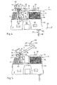
- la figure 1 est une vue en perspective d'un déclencheur électromagnétique conforme à l'invention ;
- la figure 2 est une vue en coupe d'élévation longitudinale suivant le plan de coupe II-II de la figure 1 ;
- la figure 3 est une vue en coupe d'élévation transversale partiellement selon la ligne IIIa - IIIa, et partiellement selon la ligne IIIb - IIIb de la figure 2 ;
- la figure 4 est une vue d'élévation en plan du déclencheur électromagnétique des figures précédentes, sans son couvercle, représenté dans une première position d'équilibre stable de l'armature mobile ;
- la figure 5 est une vue analogue à la figure 4, dans une deuxième position d'équilibre stable de l'armature mobile ;
- la figure 6 est une vue similaire aux figures 4 et 5, dans une troisième position d'équilibre stable de l'armature mobile ;
- la figure 7 est une vue en plan de dessus du déclencheur électromagnétique de la figure 6 ;
- la figure 8 est une vue en coupe d'élévation longitudinale selon la ligne VIII - VIII de la figure 7 ;
- la figure 9 est une vue en perspective du déclencheur électromagnétique des figures précédentes, dépourvu de son socle et de son couvercle ainsi que du bobinage de la bobine, dans la position de la figure 4 ;
- la figure 10 est une vue en perspective du déclencheur électromagnétique de la figure 9, selon un autre angle de vue ;
- la figure 11 est une vue en plan de dessus de l'armature mobile d'un déclencheur selon l'invention ;
- la figure 12 est une vue en plan d'élévation longitudinale de l'armature mobile de la figure 11 ;
- la figure 13 est une vue en perspective d'une pièce de guidage de l'armature mobile d'un déclencheur électromagnétique selon l'invention ;
- la figure 14 est une vue en plan d'élévation longitudinale de la pièce de guidage de la figure 13 ;
- la figure 15 est une vue en plan de dessus de la pièce de guidage de la figure 13 ;
- la figure 16 est une vue en plan d'élévation longitudinale de l'armature fixe d'un déclencheur électromagnétique selon l'invention ;
- la figure 17 est une vue en plan d'élévation transversale de l'armature fixe de la figure 16 ;
- la figure 18 est une vue en perspective du socle du déclencheur électromagnétique des figures 1 à 8 ;
- la figure 19 est une vue en plan de dessus du socle de la figure 18 ;
- la figure 20 est une vue en coupe d'élévation longitudinale du socle des figures 18
et 19, selon la ligne XX - XX de la figure 19 ; - la figure 21 est une vue en coupe d'élévation longitudinale du couvercle du déclencheur électromagnétique de la figure 2, représenté seul ;
- la figure 22 est une vue en plan d'élévation longitudinale de la carcasse de la bobine d'un déclencheur électromagnétique selon l'invention ;
- la figure 23 est une vue en plan de dessous de la carcasse de la figure 22 ;
- la figure 24 est une vue en coupe d'élévation longitudinale de la bobine du déclencheur électromagnétique des figures 1 à 8, selon la ligne XXIV - XXIV de la figure 7 ;
- la figure 25 est une vue en plan d'un picot entrant dans la réalisation de la bobine de la figure 24.
- Figure 1 is a perspective view of an electromagnetic release according to the invention;
- Figure 2 is a longitudinal elevation sectional view along the sectional plane II-II of Figure 1;
- Figure 3 is a cross-sectional elevational view partly along the line IIIa-IIIa, and partially along the line IIIb-IIIb of Figure 2;
- FIG. 4 is a plan elevation view of the electromagnetic release of the preceding figures, without its cover, represented in a first position of stable equilibrium of the mobile armature;
- Figure 5 is a view similar to Figure 4, in a second position of stable equilibrium of the movable armature;
- Figure 6 is a view similar to Figures 4 and 5, in a third position of stable equilibrium of the movable armature;
- Fig. 7 is a top plan view of the electromagnetic trigger of Fig. 6;
- Figure 8 is a longitudinal elevational sectional view along line VIII - VIII of Figure 7;
- Figure 9 is a perspective view of the electromagnetic release of the preceding figures, without its base and its cover and the winding of the coil, in the position of Figure 4;
- Figure 10 is a perspective view of the electromagnetic trigger of Figure 9, according to another angle of view;
- Figure 11 is a top plan view of the movable armature of a trigger according to the invention;
- Figure 12 is a longitudinal elevation plan view of the movable armature of Figure 11;
- Figure 13 is a perspective view of a guide part of the movable armature of an electromagnetic actuator according to the invention;
- Figure 14 is a longitudinal elevation plan view of the guide member of Figure 13;
- Fig. 15 is a top plan view of the guide member of Fig. 13;
- Figure 16 is a longitudinal elevation plan view of the fixed armature of an electromagnetic actuator according to the invention;
- Figure 17 is a transverse elevational plan view of the fixed armature of Figure 16;
- Figure 18 is a perspective view of the base of the electromagnetic release of Figures 1 to 8;
- Fig. 19 is a top plan view of the pedestal of Fig. 18;
- Figure 20 is a longitudinal elevational sectional view of the base of Figures 18 and 19 along the line XX - XX of Figure 19;
- Figure 21 is a longitudinal elevational sectional view of the electromagnetic release cover of Figure 2, shown alone;
- Figure 22 is a longitudinal elevational plan view of the coil casing of an electromagnetic release according to the invention;
- Figure 23 is a bottom plan view of the frame of Figure 22;
- Fig. 24 is a longitudinal elevational sectional view of the solenoid actuator coil of Figs. 1-8 taken along line XXIV-XXIV of Fig. 7;
- Figure 25 is a plan view of a pin entering the embodiment of the coil of Figure 24.
Sur les figures 1 à 3 est représenté un déclencheur électromagnétique 1 à haute sensibilité pour un interrupteur ou un disjoncteur, qui comprend, dans un boîtier 2 supposé fixe, composé d'un socle 3 coiffé d'un couvercle 4, un circuit électromagnétique 5 comprenant une armature fixe 6 en forme de U, assujettie au boîtier 2 ainsi qu'une armature mobile 7 appelée palette, susceptible de pivoter pour ouvrir ou fermer le circuit électromagnétique 5.FIGS. 1 to 3 show an
Sur les figures 1 à 3 est également représenté un repère constitué par trois directions orthogonales, à savoir :
- une direction L longitudinale orientée depuis une localisation dite arrière vers une localisation opposée dite avant ;
- une direction T transversale ; et
- une direction E d'élévation, orientée depuis une localisation dite « basse » ou « inférieure » vers une localisation opposée dite « haute » ou supérieure.
- a longitudinal direction L oriented from a so-called rear location to a so-called opposite front location;
- a transverse direction T; and
- a direction E of elevation, oriented from a so-called "low" or "lower" location to an opposite location called "high" or higher.
Pour des raisons de commodité, le déclencheur 1 est décrit par rapport à ce repère, suivant l'orientation adoptée à la figure 2, qui correspond à l'usage le plus courant du déclencheur 1.For reasons of convenience, the
Dans tout ce qui suit, les termes « avant », « arrière », « bas », « haut », « inférieur », « supérieur » sont employés en référence aux directions qui viennent d'être définies.In all that follows, the terms "before", "back", "down", "up", "lower", "higher" are used with reference to the directions that have just been defined.
L'armature fixe 6 et la palette 7 sont réalisées toutes deux dans un matériau ferromagnétique, tel qu'un alliage Fer - Nickel.The fixed
L'armature fixe 6 comprend une première branche 8 dite avant et une deuxième branche 9 dite arrière, reliées par une base 10 reposant sur le socle 3 du boîtier 2.The fixed
Le circuit électromagnétique 5 comporte une bobine 11 comprenant une carcasse 12 sur laquelle est enroulé un bobinage 13, la carcasse 12 étant enfilée sur la branche avant 8 de l'armature fixe 6 et solidaire du socle 3.The
Entre les branches 8, 9 est intercalé un aimant permanent 14 pour la polarisation magnétique de l'armature fixe 6. L'aimant 14, de forme parallélépipédique, est fixé par l'une de ses extrémités sur la base 10 de l'armature fixe 6, de préférence par soudage. Plus précisément, l'aimant 14 est fixé sur une face supérieure 15 de la base 10, qui présente également une face inférieure 16 opposée.Between the
La palette 7 est susceptible d'occuper au moins deux positions d'équilibre stable, à savoir une position de travail ou enclenchée, dans laquelle elle se trouve plaquée contre les branches 8, 9 de l'armature fixe 6 et ferme le circuit électromagnétique 5, et une position de repos ou déclenchée, dans laquelle elle est écartée de l'armature fixe 6 et ouvre le circuit électromagnétique 5.The
La palette 7 est sollicitée vers sa position déclenchée par un ressort 17 de rappel fonctionnant en traction.The
Lorsque la bobine 11 n'est pas excitée, la palette 7 est maintenue en position enclenchée à l'encontre de son ressort de rappel 17 par la force d'attraction de l'aimant permanent 14.When the
L'excitation de la bobine 11 libère la palette 7 de l'action de l'aimant 14, celle-ci pivotant alors vers sa position déclenchée, sous l'action du ressort de rappel 17.The excitation of the
La palette 7 présente deux faces planes parallèles opposées, à savoir une face supérieure 18 et une face inférieure 19.The
Les extrémités libres 20, 21 respectives des branches avant 8 et arrière 9 forment des surfaces de polarisation situées sensiblement dans un même plan de polarisation P, avec lesquelles coopère en position enclenchée la face inférieure 19 de la palette 7.The respective free ends 20, 21 of the
La palette 7 a la forme d'un trident et comporte un corps 22 de forme rectangulaire dont saillent deux ailes latérales 23, 24 coudées vers l'arrière, et dont les bords arrière 25 sont biseautés pour former des couteaux 26 pour l'articulation de la palette 7.The
Chaque couteau 26 présente une face inclinée 27 tournée vers le haut, terminée vers le bas par une arête 28 située sensiblement dans le plan de la face inférieure 19 de la palette 7. Les arêtes 28 forment ensemble un axe A de pivotement de la palette 7.Each
Sur la branche arrière 9, qui présente une face avant 29 et une face arrière 30 opposées, est fixée par encliquetage ou par tout autre moyen équivalent une plaquette 31 assurant le guidage de la palette 7, cette dernière étant montée pivotante par rapport à la plaquette 31.On the
Cette plaquette 31 est une pièce monobloc réalisée par exemple dans un matériau métallique à des fins de rigidité. Elle comporte un corps 32 plaqué contre la face arrière 30 de la branche arrière 9, qu'il recouvre sensiblement. Ce corps 32 est prolongé vers le haut, sous la forme d'une fourche, par deux pattes supérieures 33, 34 semblables qui dépassent de l'armature fixe 6 en saillant du plan de polarisation P, disposées en regard des ailes 23, 24 de la palette 7, et contre lesquelles viennent s'appliquer les couteaux 26.This
Plus précisément, chaque patte 33, 34 présente une face avant 35 d'appui contre laquelle vient s'appliquer, sous l'action du ressort de rappel 17, l'arête 28 du couteau, 26 en position enclenchée (figure 4).More specifically, each
En position déclenchée, la palette 7 est en contact linéaire, par son corps 22, avec la branche arrière 9, la face inférieure 19 de la palette 7 étant en appui sur un bord arrière 36 de l'extrémité libre 21 de la branche arrière 9 (figure 5).In the released position, the
Par ailleurs, la palette 7 présente, au niveau de ses ailes 23, 24, une extension transversale supérieure à celle de la branche arrière 9, les couteaux 26 étant en permanence écartés latéralement de celle-ci.Furthermore, the
Les couteaux 26 n'étant jamais en contact avec la branche arrière 9, ils ne produisent, lors d'une usure éventuelle, aucune particule susceptible de se déposer sur la surface de polarisation 20, 21.The
Il en résulte que l'entrefer entre la palette 7 et l'armature fixe 6 est maintenu sensiblement constant. L'efficacité, la rapidité et la durée de vie du déclencheur 1 s'en trouvent accrues.As a result, the air gap between the
La palette 7 présente vers l'arrière une queue 37 qui se prolonge au-delà des ailes 23, 24 en dépassant de celles-ci, qui se trouve, en étant libre de se mouvoir, entre les pattes 33, 34 de la plaquette 31, et dans laquelle est ancrée l'une des extrémités, supérieure 38, du ressort de rappel 17.The
Cette extrémité supérieure 38 du ressort de rappel 17 forme une boucle insérée dans un trou traversant 39 pratiqué dans la queue 37, au-delà des arêtes 28 vers l'arrière, de sorte à former un porte-à-faux permettant le pivotement de la palette 7, sous l'action du ressort 17, autour de l'axe A formé par ses arêtes 28.This
La plaquette 31 se termine vers le bas par une patte inférieure 40 repliée vers l'arrière, dans laquelle est ancrée l'autre extrémité, inférieure 41, du ressort de rappel 17.The
Les pattes supérieures 33, 34 sont prolongées chacune, vers le haut, par une extension coudée 42 formant un crochet définissant un logement 43 susceptible de recevoir la palette 7.The
Le crochet 42 comporte, vers l'arrière, un fond 44 incliné relié à la patte 33, 34 par une partie 45 repliée vers l'arrière en équerre par rapport à la patte 33, 34, et, vers le haut, un retour 46 replié en équerre vers l'avant par rapport au fond 44.The
Le fond 44 présente une surface d'appui 47 tournée vers l'avant et vers le haut, tandis que le retour 46 présente une surface d'appui 48 tournée vers l'armature fixe 6, c'est-à-dire vers l'avant et vers le bas.The bottom 44 has a bearing
La palette 7 est susceptible d'occuper une troisième position d'équilibre stable, dite levée, dans laquelle elle est inclinée et se trouve écartée de l'armature fixe 6 au-delà de la position de repos, et dans laquelle elle coopère avec le crochet 42 en étant reçue dans le logement 43 (figures 6, 7, 8).The
La queue 37 de la palette 7 présente, vers l'arrière, une partie extrême 49 d'extension transversale réduite délimitée vers l'avant par deux décrochements latéraux 50, 51 formant des butées.The
En position levée de la palette 7, ces butées 51, 52 viennent s'appliquer contre la surface d'appui 47 du fond 44 du crochet 42 avec la partie extrême 49 insérée entre les fonds 44 des crochets 42 en regard, tandis que la face supérieure 18 de la palette 7 vient s'appliquer contre la surface d'appui 48 du retour 46 du crochet 42.In the raised position of the
Dans cette position levée, la palette 7 se trouve espacée de chacune des branches 8, 9 de l'armature fixe 6, tel qu'il apparaît sur les figures 6 et 8.In this raised position, the
La palette 7 peut être déplacée vers sa position levée depuis sa position déclenchée sous l'action, par exemple, d'un dispositif automatisé de préhension (non représenté), qui vient saisir la palette 7 en position déclenchée puis, tirant sur le ressort, place la palette 7 dans la position levée en coopération avec le logement 43.The
Inversement, la palette 7 peut être rétablie en position déclenchée - ou directement en position enclenchée - à partir de la position levée, par le même dispositif automatisé de préhension, qui, venant saisir la palette 7, l'éloigne du logement 43 en tirant sur le ressort 17 pour la déposer ensuite sur l'armature fixe 6.Conversely, the
Il existe un porte-à-faux entre les butées 50, 51 et le bord arrière du trou 39, contre lequel prend appui le ressort de rappel 17, de sorte que l'action de celui-ci suffit à maintenir la palette 7 en équilibre stable dans sa position levée.There is a cantilever between the
D'ailleurs, afin d'accroître la stabilité de cet équilibre, le ressort 17 est légèrement incliné vers l'arrière, depuis le haut vers le bas.Moreover, in order to increase the stability of this balance, the
Dans cette position, il est possible d'accéder au circuit électromagnétique pour procéder à son nettoyage afin de le débarrasser, particulièrement au niveau des surfaces polaires 20, 21 des branches 8, 9 et de la face inférieure 19 de la palette 7, de toute impureté susceptible d'enrayer le bon fonctionnement ultérieur du déclencheur 1, notamment en modifiant l'entrefer entre la palette 7 et l'armature fixe 6.In this position, it is possible to access the electromagnetic circuit to clean it in order to get rid of it, especially at the
Ce nettoyage, qui a lieu notamment au montage du déclencheur 1, peut être réalisé par ultrasons, par aspersion, notamment par aspersion cryogénique telle qu'un jet de dioxyde de carbone, ou par tout autre procédé équivalent connu de l'homme du métier.This cleaning, which takes place in particular when mounting the
Il est à noter que, dans cette position levée, les couteaux 26 sont libres, espacés des crochets 42, et préservés de tout choc susceptible de les endommager (figure 6).It should be noted that, in this raised position, the
Les parties 45 des crochets 42 repliées vers l'arrière présentent chacune un décrochement 52 vers l'intérieur, que contourne la palette 7 pendant son passage depuis la position déclenchée vers la position levée, avant de venir se plaquer contre le fond 44 du crochet 42.The
Par ailleurs, afin de réaliser la fixation de la plaquette 31 à la branche arrière 9, la plaquette 31 comporte, dans sa partie inférieure, des moyens d'encliquetage intégrés sous la forme de deux bras 54, 55 saillant du corps 32 dans sa partie inférieure, venus de matière avec lui et repliés en équerre vers l'avant, et qui encadrent la branche arrière 9 à proximité de la base 10 de l'armature fixe 6.Furthermore, in order to fix the
Afin d'assurer l'immobilisation de la plaquette 31 en élévation, les bras 54, 55 sont disposés entre, d'une part, vers le haut, deux oreilles 56, 57 saillant transversalement de la branche arrière 9 environ à mi-hauteur de celle-ci, et d'autre part, vers le bas, la base 10 de l'armature fixe 6.In order to ensure the immobilization of the
Chaque bras 54, 55 présente en outre, sur sa tranche supérieure au voisinage du corps 32, une bosse 53 en saillie vers le haut et qui, sous l'effet de la tension du ressort 17 sur la plaquette 31, se trouve en appui contre une face inférieure de l'oreille correspondante 56, 57 de sorte à rattraper les jeux d'élévation susceptibles d'apparaître entre la plaquette 31 et l'armature fixe 9.Each
Les bras 54, 55 sont flexibles de manière élastique, et présentent chacun un bossage 58 saillant vers l'intérieur.The
Dans chaque bras 54, 55 est réalisée, au niveau du bossage 58, une découpe en U ou en V délimitant une dent 59 qui saille du bras 54, 55 vers le corps 32 de la plaquette 31, et présente une surface d'appui 60 tournée vers l'arrière qui regarde le corps 32.In each
Compte tenu de la rigidité de la plaquette 31, son encliquetage sur la branche arrière 9 peut être réalisé de manière automatique par une machine spécifique (non représentée), qui, par exemple, écarte préalablement les bras 54, 55 afin de ne pas endommager la branche 9.Given the rigidity of the
Afin d'assurer un maintien ferme de la plaquette 31 sur la branche arrière 9, le corps 32 de plaquette présente, en regard et au droit des dents 59, une languette 61 formée par une découpe en V dans le corps 32 de plaquette et qui, en l'absence de sollicitation, est inclinée vers l'avant.In order to firmly hold the
La languette 61 présente une certaine élasticité pour que, en position encliquetée, la branche arrière 9 se trouve serrée entre les dents 59 et cette languette 61.The
La conformation de la plaquette 31, notamment des bras 54, 55, par rapport à l'armature fixe, est ainsi apte, à elle seule, à permettre la fixation rigide par encliquetage, de la plaquette 31 sur l'armature fixe 6.The conformation of the
L'on décrit à présent le montage du déclencheur 1.The arrangement of the
Le socle 3 et le couvercle 4 sont deux pièces monobloc réalisées chacune par moulage d'un matériau synthétique tel que PVC, polypropylène, polyoxyméthylène, ou équivalent.The
Le socle 3 comprend une paroi de fond 62 sur laquelle repose le circuit électromagnétique 5, bordée par deux parois latérales 63, 64 en regard, dont saillent des dents 65 vers l'extérieur pour l'encliquetage du couvercle 4.The
Les parois latérales 63, 64 s'étendent vers l'avant au-delà de la paroi de fond 62, et le socle 3 présente, à l'avant, un trou 66 traversant à section rectangulaire, étendu d'une paroi 63 à l'autre 64.The
Ce trou 66 est bordé vers l'avant par une traverse 67 formant l'extrémité avant du socle 3, et vers l'arrière par une cloison 68 qui le sépare de la paroi de fond 62.This
Le socle 3 présente en outre deux paires identiques de tétons 69, 70 disposées en regard transversalement, à chacune des jonctions entre le socle 3 et les parois latérales 63, 64. Chaque paire comprend un premier 69 et un deuxième 70 tétons saillant vers le haut et vers l'intérieur, à la jonction entre la paroi latérale 63, 64 et la paroi de fond 62.The
Le premier téton 69, situé à proximité de la cloison 68, présente des dimensions transversale et d'élévation respectivement supérieure et inférieure à celles du deuxième téton 70.The
Chaque téton 69, 70 est arrondi vers l'intérieur, les tétons 69, 70 délimitant ensemble, au droit de la paroi de fond 62, une zone de réception 71 de la base 10 de l'armature fixe 6.Each
La paroi de fond 62 présente, au droit de la zone de réception 71, une zone 72 déformable élastiquement, cette zone 72 étant plus particulièrement apte à s'enfoncer élastiquement vers le bas sous l'effet d'une pression qui lui serait appliquée de haut en bas.The
Le socle 3 présente, à proximité du centre de cette zone déformable 72, un pion 73 qui saille de la paroi de fond 62 vers le haut et présente une extrémité libre 74 formant une surface d'appui localisée par rapport à la zone déformable 72.The
Afin de permettre la déformation élastique de la paroi de fond 62, cette zone 72 est ici inscrite dans un cercle à l'intérieur duquel la paroi de fond 62 présente une section conique à conicité tournée vers le bas, la paroi de fond 62 s'amincissant depuis le bord dudit cercle vers son centre - c'est-à-dire au droit du pion 73.In order to allow the elastic deformation of the
Le couvercle 4 est quant à lui une pièce creuse, de forme généralement parallélépipédique, présentant une paroi supérieure 75 bordée par une paroi avant 76, une paroi arrière 77, et deux parois latérales 78, 79 qui définissent ensemble, vers le bas, une ouverture 80 par laquelle le couvercle 4 est destiné à être associé au socle 3.The
A proximité de l'ouverture 80, chaque paroi latérale 78, 79 comporte deux pattes 81 jumelées dans chacune desquelles est réalisée une fenêtre 82 destinée à coopérer avec l'une des dents 65 du socle 3 pour réaliser l'encliquetage du couvercle 4.Near the
Afin de favoriser la flexion des pattes 81 et le guidage du couvercle 4 lors de son encliquetage, chaque paroi latérale 78, 79 présente une encoche 83 entre les pattes 81, destinée à coopérer avec un bourrelet 84 complémentaire en saillie vers l'extérieur sur chaque paroi latérale 63, 64 du socle 3.In order to promote the flexing of the
Chaque paroi latérale 78, 79 du couvercle 4 présente en outre une surface intérieure 85 le long de laquelle court une nervure 86 saillant vers l'intérieur, qui s'étend depuis la paroi supérieure 75 vers l'ouverture 80. Cette nervure 86 présente une partie extrême inférieure 87 saillant de l'encoche 83 vers le bas, terminée par une surface 88 formant butée.Each
Lors du montage du déclencheur 1, l'armature fixe 6 est disposée sur le socle 3, sa base 10 étant placée dans la zone de réception 71, qui lui est complémentaire, en étant insérée entre les tétons 69, 70 qui encadrent la zone déformable 72 et qui, formant des cales, limitent le débattement longitudinal et éventuellement transversal de l'armature fixe 6 , la limitation du débattement transversal pouvant également être réalisée par les parois latérales 63, 64.When mounting the
La face inférieure 16 de la base repose sur le pion 73 en étant en contact avec la surface d'appui 74 de celui-ci, qui est de superficie limitée par rapport à celle de la zone déformable 72 afin de concentrer les contraintes.The
L'encliquetage du couvercle 4 sur le socle 3, avec la butée 88 de la nervure 86 regardant la zone déformable 72, provoque, par les dimensions et la conformation du socle 3, du couvercle 4 et de la base 10 de l'armature fixe 6, l'appui de cette butée 88 contre la face supérieure 15 de la base 10 à l'encontre de la sollicitation de la zone déformable 72.The latching of the
La base 10 se trouve alors serrée, maintenue, immobilisée en élévation entre le pion 73 et la nervure 86, la zone déformable 72 sollicitant, sous l'effet de son élasticité propre, la base 10 vers le couvercle 4.The
Sous l'effet de la pression de la nervure 86 contre la face supérieure 15 de la base 10 de l'armature fixe 6, la base 10 appuie sur le pion 73, ce qui provoque l'enfoncement de la zone déformable 72 et, par l'élasticité de cette dernière, le rattrapage des jeux susceptibles d'apparaître entre la base 10 de l'armature fixe 6, le socle 3, et le couvercle 4, et le positionnement précis de l'armature fixe 6 par rapport au boîtier 2.Under the effect of the pressure of the
En outre, le couvercle 4 présente, sur ses parois avant 76 et arrière 77, deux pattes de fixation 89, 90 perforées ou creusées en forme d'oreille, permettant d'assurer la fixation du déclencheur 1 sur un appareil de protection différentielle (non représenté) bistable susceptible d'être actionné par le déclencheur 1.In addition, the
A cet effet, le déclencheur 1 comporte un dispositif d'actionnement 119 qui comprend un poussoir 114 inséré dans un trou traversant 115 pratiqué dans la paroi supérieure 75 du couvercle 4, au droit du corps 22 de palette.For this purpose, the
Le poussoir 114 comprend une partie extrême supérieure 116 saillant de la paroi supérieure 75 vers l'extérieur et susceptible de coopérer avec l'appareil de protection différentielle, et une partie extrême inférieure 117 saillant de cette paroi 75 vers l'intérieur, et dont le bout forme ou porte une tête 118 hémisphérique susceptible de coopérer avec le corps de palette 22.The
L'on décrit succinctement le fonctionnement du déclencheur 1.The operation of
La palette 7 est supposée se trouver dans sa position enclenchée, le poussoir 114 se trouvant dans une position dite enfoncée où la tête 118, qui est en appui contre le corps de palette 22, se trouve à distance de la paroi 75 (figures 2, 3).The
Lorsqu'un courant parcourt le bobinage 13, le champ magnétique induit perturbe le champ magnétique de l'aimant permanent 14. Cette perturbation provoque la libération de la palette 7, qui pivote sous l'action du ressort 17 vers sa position déclenchée en entraînant le poussoir 114 vers une position dite remontée (figure 5) où la partie extrême supérieure 116 provoque le déclenchement de l'appareil de protection différentielle.When a current flows through the winding 13, the induced magnetic field disturbs the magnetic field of the
Sous l'action d'une contrainte mécanique extérieure appliquée sur la partie extrême supérieure 116, et dirigée depuis le haut vers le bas, le poussoir 114 retrouve sa position enfoncée en forçant la palette 7 à occuper sa position enclenchée.Under the action of an external mechanical stress applied to the
L'on comprend que de la précision du positionnement du poussoir 114 par rapport au boîtier 2 dépend la précision d'action du déclencheur 1, tant en position déclenchée qu'en position enclenchée.It is understood that the accuracy of the positioning of the
En position enclenchée, la position d'élévation du poussoir 114 dépend du positionnement en élévation des armatures 6, 7, c'est-à-dire, compte tenu du fait que la palette 7 se trouve prise entre le poussoir 114 et l'armature fixe 6, du positionnement de l'armature fixe 6 par rapport au boîtier 2. Ce positionnement étant précis, comme on l'a vu ci-dessus, la précision du positionnement du poussoir 114 par rapport au boîtier 2 est donc assurée.In the engaged position, the elevation position of the
Revenons à présent à la bobine 11 et à sa carcasse 12.Now back to reel 11 and its
La carcasse 12 comprend un flasque inférieur 91 et un flasque supérieur 92 encadrant le bobinage 13, reliés par une âme 93 creuse enfilée sur la branche avant 8, et présentant un trou 94 traversant dont la forme est complémentaire de celle-ci.The
La carcasse 12 comprend en outre un pied 95 à section rectangulaire qui saille du flasque inférieur 91, vers le bas. La carcasse 12 est assemblée au socle 3 par enfoncement de son pied 95 dans le trou 66. Les dimensions relatives du pied 95 et du trou 66 sont choisies pour que, une fois enfoncé dans le trou 94, le pied 95 soit monté serré dans ce dernier, de sorte que la carcasse 12, une fois assemblée, soit maintenue fermement dans une position prédéterminée fixe.The
Le pied 95 présente deux trous traversants 96 dans chacun desquels est inséré un picot 97 métallique présentant une partie inférieure 98 saillante destinée à être connectée au circuit électrique, ainsi qu'une partie supérieure 99 saillante destinée à être associée au fil du bobinage 13, par exemple par soudage.The
Avant son assemblage à la carcasse 12, le picot 97 a sensiblement la forme d'un J, sa partie inférieure 98 étant de dimension transversale supérieure à celle de sa partie supérieure 99 (figure 25).Before it is assembled to the
Chaque picot 97 présente à proximité de son centre, c'est-à-dire à la jonction entre ses parties inférieure 98 et supérieure 99, un décrochement 100 formant une butée qui, lorsque le picot 97 est inséré dans le trou 96 correspondant dans le pied 95, vient s'appliquer contre une surface d'appui 101 transversale ménagée dans le trou 96.Each
Afin de réaliser l'immobilisation du picot 97 dans le pied 95 pour le rendre solidaire de la carcasse 12, sa partie supérieure 99 est repliée en Z vers l'avant. La partie supérieure 99 présente, à une certaine distance du décrochement 100, un rétrécissement 102 qui, lorsque la partie supérieure 99 est repliée, forme la branche centrale du Z et vient se loger dans une encoche 103 complémentaire réalisée dans la surface supérieure du flasque inférieur 91, et adjacente au trou 96.In order to immobilize the
Le picot 97 se trouve ainsi immobilisé en translation selon la direction d'élévation.The
La branche avant 8 de l'armature fixe 6 présente une face avant 104 et une face arrière 105 opposées, reliées par deux faces latérales 106, 107. Le trou traversant 94 de l'âme 93 de la carcasse 12 présente, lui aussi, une face avant 108 et une face arrière 109 opposées, reliées par deux faces latérales 110, 111.The
Les dimensions et la conformation du socle 3, de l'armature fixe 6 et de la carcasse 12 sont choisies pour que, une fois ces pièces assemblées, il existe de toute part un jeu entre la branche avant 8 et la carcasse 12, à savoir :
- un premier jeu J1 entre la
face avant 104 de la branche avant 8 etla face arrière 109 dutrou 94 de l'âme 93 en regard ; - un deuxième jeu J2 entre la
face arrière 105 de la branche avant 8 etla face avant 108 dutrou 94 de l'âme 93 en regard ; - un troisième J3 et un quatrième J4 jeux entre les faces latérales respectives 106, 107, 110, 111 de la branche avant 8 et du
trou 94 de l'âme 93 en regard.
- a first game J1 between the
front face 104 of thefront branch 8 and therear face 109 of thehole 94 of the core 93 opposite; - a second clearance J2 between the
rear face 105 of thefront branch 8 and thefront face 108 of thehole 94 of the core 93 opposite; - a third J3 and a fourth J4 clearance between the respective lateral faces 106, 107, 110, 111 of the
front branch 8 and thehole 94 of the core 93 opposite.
Chaque jeu J1, J2, J3, J4 est ici prédéterminé par la chaîne de cotes la plus courte reliant directement les surfaces de jonction de l'armature fixe 6, du socle 3 et de la carcasse 12, en partant d'une surface terminale formée par une face 104, 105, 106, 107 de la branche avant 8 délimitant ledit jeu, pour aboutir à la face 108, 109, 110, 111 du trou 94 en regard, formant une autre surface terminale délimitant le même jeu J1, J2, J3, J4.Each set J1, J2, J3, J4 is here predetermined by the shortest dimension chain directly connecting the junction surfaces of the fixed
Par ailleurs, la dimension d'élévation ou hauteur de la carcasse 12, mesurée entre les faces non en regard des flasques, c'est-à-dire une face inférieure 112 du flasque inférieur 91 et une face supérieure 113 du flasque supérieur 92, est choisie inférieure à la dimension d'élévation ou hauteur de la branche avant 8, c'est-à-dire la distance séparant la face supérieure 15 de la base 10 de la surface de polarisation 20.Moreover, the dimension of elevation or height of the
Ainsi, lors du montage du déclencheur 1, le pied 95 est enfoncé dans le trou 66 selon une profondeur prédéterminée, telle que, d'une part, la branche avant 8 dépasse du flasque supérieur 92, l'extrémité libre 20 de la branche avant 8 saillant de la face supérieure 113 du flasque supérieur 92, et, d'autre part, la face inférieure 112 du flasque inférieur 91 soit espacée de la face supérieure 15 de la base 10 de sorte qu'il existe un jeu J5 entre elles (figure 2).Thus, during the mounting of the
De la sorte, la carcasse 12 est montée rigidement par rapport au boîtier, tout en étant montée flottante par rapport à l'armature fixe 6, c'est-à-dire espacée de celle-ci en tout point. L'armature fixe 6 est ainsi préservée des contraintes et déformations auxquelles est soumise la carcasse 12, notamment lors du montage des picots 97 sur le circuit électrique précité.In this way, the
Claims (21)
- An electromagnetic release device comprising, in a casing (2) comprising a support (3) capped by a cover (4), an electromagnetic circuit (5) comprising a fixed core (6) resting on the support (3), as well as a moveable core (7) adapted to open and close the electromagnetic circuit (5), said fixed core (6) being received between the support (3) and the cover (4), characterized in that the support (3) comprises an elastically deformable region (72), adapted to be depressed by being pushed on by the core (6), the dimensions and the form of the support (3), of the cover (4) and of the fixed core (6) being adapted to enable the fixed core (6) to be clamped between the cover (4) and said deformable region (72) which urges it towards the cover (3) under the effect of its own elasticity.
- An electromagnetic release device according to claim 1, characterized in that the support (3) comprises, in said deformable region (72), a localized bearing surface (74), through which the support (3) is in contact with the fixed core (6).
- A electromagnetic release device according to claim 2, characterized in that said bearing surface (74) belongs to a projection (73) projecting from the support (3) in said deformable region (72).
- A electromagnetic release device according to claim 3, characterized in that said projection (73) occupies a median position in said deformable region (72).
- An electromagnetic release device according to claim 4, characterized in that said deformable region (72) gets thinner from its edge towards its centre.
- An electromagnetic release device according to one of claims 1 to 5, characterized in that the fixed core (6) is positioned, in register with the deformable region (72), by four nipples (69, 70) belonging to the rest of the support (3) and bounding said deformable region (72).
- An electromagnetic release device according to one of claims 1 to 6, characterized in that the cover (4) has a stop surface (88) facing said deformable region (72), and by which it bears on the fixed core (6) on the opposite side from the deformable region (72).
- A electromagnetic release device according to claim 7, characterized in that said bearing surface (88) belongs to a rib (86) projecting from a wall (78,79) of the cover (4).
- An electromagnetic release device according to one of claims 1 to 8, characterized in that the support (3) and the cover (4) are assembled by snap-fitting.
- An electromagnetic release device according to claim 9, characterized in that the support (3) has projecting teeth (65) adapted to cooperate, during the assembly, with windows (82) formed in the cover (4).
- An electromagnetic release device according to one of claims 1 to 10, characterized in that said fixed core (6) is U-shaped, and comprises a first and a second arm (8, 9) connected by a base (10) which is clamped between the support (3) and the cover (4).
- An electromagnetic release device according to one of claims 1 to 11, characterized in that said moveable core (7) is a pivoting armature adapted to occupy two positions of stable equilibrium, i.e. a working position in which it is pressed against the fixed core (6) and closes the electromagnetic circuit (5), and a resting position in which it is separated from the fixed core (6) and opens the electromagnetic circuit (5).
- An electromagnetic release device according to one of claims 1 to 12, characterized in that it comprises a coil (11) comprising a former (12) on which a winding (13) is wound, said former (12) being threaded onto the fixed core (6) and attached to the casing (2).
- An electromagnetic release device according to claim 13, characterized in that the former (12) is rigidly mounted with respect to the casing (2) and floating with respect to the fixed core (6).
- An electromagnetic release device according to claim 14, characterized in that the former (12) comprises first and second flanges (91, 92) connected by a hollow mid-part (93) threaded onto the fixed core (6), the former (12) being attached to the support (3).
- An electromagnetic release device according to claim 15, characterized in that the form of the support (3), of the fixed core (6) and of the former (12) are chosen in order for there to be play (J1 to J5) at all points between the fixed core (6) and the mid-part (93) of the armature (12)
- An electromagnetic release device according to claim 15 or 16, characterized in that the fixed core (6) is U-shaped, and comprises a first and a second arm (8, 9) connected by a base (10), the former (12) of said coil (11) being threaded onto said first arm (8), play (J1 to J5) being provided between the mid-part (83) of the former (12) and the first arm (8), as well as between the first flange (91) and the base (10).
- A electromagnetic release device according to one of claims 15 to 17, characterized in that the former (12) is provided with a foot (95) projecting from the first flange (91), and inserted into a corresponding hole (66) in the support (3), said foot (95) being inserted into said hole (66) to a predetermined depth such that the fixed core (6) presents a portion which extends beyond the second flange (92), with there nevertheless being play (J5) between the first flange (91) and the fixed core (6).
- An electromagnetic release device according to claim 18, characterized in that the relative dimensions of the foot (95) and of the hole (66) are chosen in order for the foot (95) to be a tight fit in the hole (66), such that the former (12) is held in a predetermined fixed position.
- An electromagnetic release device according to claim 18 or 19, characterized in that the foot (95) has two through holes (96) in each of which is inserted a metal pin (97) projecting either side of said through hole (96) and fastened to the former (12).
- An electromagnetic release device according to claim 20, characterized in that said pin (97) has a stop (100) which comes into abutment with a bearing surface (101) provided in said through hole (96), as well as a folded portion (102) which locates in a corresponding cut-out (103) provided in the former (12), such that the pin (97) is prevented from moving with respect to said foot (95).
Applications Claiming Priority (2)
| Application Number | Priority Date | Filing Date | Title |
|---|---|---|---|
| FR0104720 | 2001-04-06 | ||
| FR0104720A FR2823369B1 (en) | 2001-04-06 | 2001-04-06 | ELECTROMAGNETIC TRIGGER COMPRISING AN ELECTROMAGNETIC CIRCUIT BASED ON AN ELASTICALLY DEFORMABLE BASE AND ELECTROMAGNETIC TRIGGER INCLUDING A FLOATING COIL |
Publications (2)
| Publication Number | Publication Date |
|---|---|
| EP1248277A1 EP1248277A1 (en) | 2002-10-09 |
| EP1248277B1 true EP1248277B1 (en) | 2006-05-24 |
Family
ID=8862043
Family Applications (1)
| Application Number | Title | Priority Date | Filing Date |
|---|---|---|---|
| EP02290798A Expired - Fee Related EP1248277B1 (en) | 2001-04-06 | 2002-03-29 | Electromagnetic tripdevice having an elastically socket mounted electromagnetic circuit and an electromagnetic tripdevice having a floating coil |
Country Status (6)
| Country | Link |
|---|---|
| EP (1) | EP1248277B1 (en) |
| CN (1) | CN1260761C (en) |
| AT (1) | ATE327567T1 (en) |
| DE (1) | DE60211586T2 (en) |
| FR (1) | FR2823369B1 (en) |
| PL (1) | PL200462B1 (en) |
Families Citing this family (6)
| Publication number | Priority date | Publication date | Assignee | Title |
|---|---|---|---|---|
| JP4321256B2 (en) * | 2003-12-22 | 2009-08-26 | オムロン株式会社 | Electromagnetic relay |
| CN1303627C (en) * | 2004-01-30 | 2007-03-07 | 厦门宏发电声有限公司 | Low height press-button type small-sized large power AC-DC electromagnetic relay |
| FR2877137B1 (en) * | 2004-10-21 | 2006-12-22 | Schneider Electric Ind Sas | ELECTROMAGNETIC TRIGGER AND ELECTRIC PROTECTION APPARATUS HAVING THE SAME |
| CN104282508B (en) * | 2014-10-13 | 2016-08-24 | 浙江正泰电器股份有限公司 | A kind of electromagnetic trip device with tripping mechanism |
| CN106206171B (en) * | 2016-08-31 | 2023-10-03 | 陕西群力电工有限责任公司 | Radio frequency relay for realizing dynamic function |
| FR3118334B1 (en) | 2020-12-18 | 2022-12-23 | Legrand France | Electrical device for the protection of an alternating current electrical installation |
Family Cites Families (5)
| Publication number | Priority date | Publication date | Assignee | Title |
|---|---|---|---|---|
| FR2406885A1 (en) * | 1977-10-18 | 1979-05-18 | Telemecanique Electrique | ELECTRO-MAGNET FOR CONTACTOR SUPPLIED WITH DIRECT CURRENT |
| FR2589623B1 (en) * | 1985-10-31 | 1989-12-22 | Itt Composants Instr | ELECTROMAGNETIC RELAY |
| FR2620264B1 (en) * | 1987-09-03 | 1989-12-01 | Merlin Gerin | MAGNETIC TRIGGER WITH KNIFE JOINT |
| FR2630256B1 (en) * | 1988-04-14 | 1995-06-23 | Merlin Gerin | HIGH SENSITIVITY ELECTROMAGNETIC TRIGGER |
| SE9303637L (en) * | 1993-11-04 | 1995-05-05 | Asea Brown Boveri | Electromagnetically operated electric switch |
-
2001
- 2001-04-06 FR FR0104720A patent/FR2823369B1/en not_active Expired - Fee Related
-
2002
- 2002-03-29 AT AT02290798T patent/ATE327567T1/en not_active IP Right Cessation
- 2002-03-29 EP EP02290798A patent/EP1248277B1/en not_active Expired - Fee Related
- 2002-03-29 DE DE60211586T patent/DE60211586T2/en not_active Expired - Lifetime
- 2002-04-05 CN CN02106156.4A patent/CN1260761C/en not_active Expired - Fee Related
- 2002-04-05 PL PL353227A patent/PL200462B1/en unknown
Also Published As
| Publication number | Publication date |
|---|---|
| FR2823369B1 (en) | 2003-10-24 |
| PL353227A1 (en) | 2002-10-07 |
| ATE327567T1 (en) | 2006-06-15 |
| CN1387210A (en) | 2002-12-25 |
| FR2823369A1 (en) | 2002-10-11 |
| DE60211586T2 (en) | 2007-05-10 |
| EP1248277A1 (en) | 2002-10-09 |
| PL200462B1 (en) | 2009-01-30 |
| CN1260761C (en) | 2006-06-21 |
| DE60211586D1 (en) | 2006-06-29 |
Similar Documents
| Publication | Publication Date | Title |
|---|---|---|
| EP1157398B1 (en) | Sealed individual electric switch fixed by being interlocked on a circuit board | |
| EP0570647B1 (en) | Switch latch for a circuit breaker and circuit breakers incorporating it | |
| EP0633591A1 (en) | Actuating mechanism for electric modular circuit breaker | |
| EP0140761A2 (en) | Operating mechanism for a low-voltage multi-pole circuit breaker | |
| EP1586726A1 (en) | Opening and closing mechanism for a vehicle door | |
| EP1248277B1 (en) | Electromagnetic tripdevice having an elastically socket mounted electromagnetic circuit and an electromagnetic tripdevice having a floating coil | |
| EP1916683B1 (en) | Electric connection module between a first and second contactor and corresponding inverter installation | |
| EP0016169B1 (en) | Buckle for a safety belt for vehicles | |
| EP0467761B1 (en) | Container provided with a one-piece catch | |
| FR2689100A1 (en) | Container structure - has pivoting cover operated by flexible rod, whose reaction force maintains cover sealed on container body, and locking mechanism for closed position | |
| EP1901327B1 (en) | Mechanism with two stable positions and electrical control device comprising same | |
| FR2604293A1 (en) | ELECTROMAGNETIC DEVICE FOR CONTROLLING THE POWER SUPPLY OF THE ELECTRIC STARTER OF AN INTERNAL COMBUSTION ENGINE | |
| EP0205379B1 (en) | Buckle, in particular for safety belts | |
| FR2555803A1 (en) | COUPLING DEVICE BETWEEN AN ELECTROMAGNETIC SWITCH AND A UNIT WITH AUXILIARY CONTACTS REMOVABLY MOUNTED THEREON | |
| EP1248278B1 (en) | Electromagnetic tripdevice with an electromagnetic circuit and an armature capable of maintaining three stable poritions | |
| FR2555805A1 (en) | ELECTROMAGNETIC COMB RELAY | |
| EP0211718B1 (en) | Buckle, especially for a safety belt in a motor vehicle | |
| EP0188143B1 (en) | Protective switching device | |
| FR2823370A1 (en) | Electromagnetic trigger with movable armature and fixed yoke has armature guide part and latching arrangement ensuring rigid attachment of guide part to the yoke | |
| FR2788549A1 (en) | LOCK FOR AUTOMOTIVE EQUIPMENT SUCH AS DOOR LOCK, TRUNK OR FOLDING SEAT BACKREST | |
| EP0325501B1 (en) | Automatic switches, in particular differential switches and circuit breakers | |
| EP2304755B1 (en) | Arc extinction cage | |
| EP0040384A1 (en) | Apparatus for locking-unlocking a cable on an insulator cap | |
| FR2674679A1 (en) | LOCK MECHANISM FOR CIRCUIT BREAKER. | |
| EP0225248B1 (en) | Safety belt buckle, in particular for a motor vehicle |
Legal Events
| Date | Code | Title | Description |
|---|---|---|---|
| PUAI | Public reference made under article 153(3) epc to a published international application that has entered the european phase |
Free format text: ORIGINAL CODE: 0009012 |
|
| AK | Designated contracting states |
Kind code of ref document: A1 Designated state(s): AT BE CH CY DE DK ES FI FR GB GR IE IT LI LU MC NL PT SE TR |
|
| AX | Request for extension of the european patent |
Free format text: AL;LT;LV;MK;RO;SI |
|
| 17P | Request for examination filed |
Effective date: 20030403 |
|
| AKX | Designation fees paid |
Designated state(s): AT DE ES GR IT TR |
|
| 17Q | First examination report despatched |
Effective date: 20050330 |
|
| GRAP | Despatch of communication of intention to grant a patent |
Free format text: ORIGINAL CODE: EPIDOSNIGR1 |
|
| GRAS | Grant fee paid |
Free format text: ORIGINAL CODE: EPIDOSNIGR3 |
|
| GRAA | (expected) grant |
Free format text: ORIGINAL CODE: 0009210 |
|
| AK | Designated contracting states |
Kind code of ref document: B1 Designated state(s): AT DE ES GR IT TR |
|
| PG25 | Lapsed in a contracting state [announced via postgrant information from national office to epo] |
Ref country code: IT Free format text: LAPSE BECAUSE OF FAILURE TO SUBMIT A TRANSLATION OF THE DESCRIPTION OR TO PAY THE FEE WITHIN THE PRESCRIBED TIME-LIMIT;WARNING: LAPSES OF ITALIAN PATENTS WITH EFFECTIVE DATE BEFORE 2007 MAY HAVE OCCURRED AT ANY TIME BEFORE 2007. THE CORRECT EFFECTIVE DATE MAY BE DIFFERENT FROM THE ONE RECORDED. Effective date: 20060524 |
|
| REF | Corresponds to: |
Ref document number: 60211586 Country of ref document: DE Date of ref document: 20060629 Kind code of ref document: P |
|
| PG25 | Lapsed in a contracting state [announced via postgrant information from national office to epo] |
Ref country code: ES Free format text: LAPSE BECAUSE OF FAILURE TO SUBMIT A TRANSLATION OF THE DESCRIPTION OR TO PAY THE FEE WITHIN THE PRESCRIBED TIME-LIMIT Effective date: 20060904 |
|
| PLBE | No opposition filed within time limit |
Free format text: ORIGINAL CODE: 0009261 |
|
| STAA | Information on the status of an ep patent application or granted ep patent |
Free format text: STATUS: NO OPPOSITION FILED WITHIN TIME LIMIT |
|
| 26N | No opposition filed |
Effective date: 20070227 |
|
| PG25 | Lapsed in a contracting state [announced via postgrant information from national office to epo] |
Ref country code: GR Free format text: LAPSE BECAUSE OF FAILURE TO SUBMIT A TRANSLATION OF THE DESCRIPTION OR TO PAY THE FEE WITHIN THE PRESCRIBED TIME-LIMIT Effective date: 20060825 |
|
| PGFP | Annual fee paid to national office [announced via postgrant information from national office to epo] |
Ref country code: AT Payment date: 20090218 Year of fee payment: 8 |
|
| PG25 | Lapsed in a contracting state [announced via postgrant information from national office to epo] |
Ref country code: TR Free format text: LAPSE BECAUSE OF FAILURE TO SUBMIT A TRANSLATION OF THE DESCRIPTION OR TO PAY THE FEE WITHIN THE PRESCRIBED TIME-LIMIT Effective date: 20060524 |
|
| PG25 | Lapsed in a contracting state [announced via postgrant information from national office to epo] |
Ref country code: AT Free format text: LAPSE BECAUSE OF NON-PAYMENT OF DUE FEES Effective date: 20100329 |
|
| PGFP | Annual fee paid to national office [announced via postgrant information from national office to epo] |
Ref country code: DE Payment date: 20150311 Year of fee payment: 14 |
|
| REG | Reference to a national code |
Ref country code: DE Ref legal event code: R119 Ref document number: 60211586 Country of ref document: DE |
|
| PG25 | Lapsed in a contracting state [announced via postgrant information from national office to epo] |
Ref country code: DE Free format text: LAPSE BECAUSE OF NON-PAYMENT OF DUE FEES Effective date: 20161001 |
|
| PGFP | Annual fee paid to national office [announced via postgrant information from national office to epo] |
Ref country code: IT Payment date: 20180309 Year of fee payment: 17 |
|
| PG25 | Lapsed in a contracting state [announced via postgrant information from national office to epo] |
Ref country code: IT Free format text: LAPSE BECAUSE OF NON-PAYMENT OF DUE FEES Effective date: 20190329 |