EP1248274B1 - Switch assembly of an automobile having a load absorbing apparatus - Google Patents
Switch assembly of an automobile having a load absorbing apparatus Download PDFInfo
- Publication number
- EP1248274B1 EP1248274B1 EP02252444A EP02252444A EP1248274B1 EP 1248274 B1 EP1248274 B1 EP 1248274B1 EP 02252444 A EP02252444 A EP 02252444A EP 02252444 A EP02252444 A EP 02252444A EP 1248274 B1 EP1248274 B1 EP 1248274B1
- Authority
- EP
- European Patent Office
- Prior art keywords
- housing
- knob
- circuit board
- shaft
- switch assembly
- Prior art date
- Legal status (The legal status is an assumption and is not a legal conclusion. Google has not performed a legal analysis and makes no representation as to the accuracy of the status listed.)
- Expired - Lifetime
Links
Images








Classifications
-
- B—PERFORMING OPERATIONS; TRANSPORTING
- B60—VEHICLES IN GENERAL
- B60R—VEHICLES, VEHICLE FITTINGS, OR VEHICLE PARTS, NOT OTHERWISE PROVIDED FOR
- B60R21/00—Arrangements or fittings on vehicles for protecting or preventing injuries to occupants or pedestrians in case of accidents or other traffic risks
- B60R21/02—Occupant safety arrangements or fittings, e.g. crash pads
- B60R21/055—Padded or energy-absorbing fittings, e.g. seat belt anchors
-
- H—ELECTRICITY
- H01—ELECTRIC ELEMENTS
- H01H—ELECTRIC SWITCHES; RELAYS; SELECTORS; EMERGENCY PROTECTIVE DEVICES
- H01H3/00—Mechanisms for operating contacts
- H01H3/02—Operating parts, i.e. for operating driving mechanism by a mechanical force external to the switch
- H01H3/08—Turn knobs
-
- H—ELECTRICITY
- H01—ELECTRIC ELEMENTS
- H01H—ELECTRIC SWITCHES; RELAYS; SELECTORS; EMERGENCY PROTECTIVE DEVICES
- H01H3/00—Mechanisms for operating contacts
- H01H3/02—Operating parts, i.e. for operating driving mechanism by a mechanical force external to the switch
- H01H2003/026—Operating parts, i.e. for operating driving mechanism by a mechanical force external to the switch specially adapted to avoid injury to occupants of a car during an accident
-
- H—ELECTRICITY
- H01—ELECTRIC ELEMENTS
- H01H—ELECTRIC SWITCHES; RELAYS; SELECTORS; EMERGENCY PROTECTIVE DEVICES
- H01H3/00—Mechanisms for operating contacts
- H01H3/02—Operating parts, i.e. for operating driving mechanism by a mechanical force external to the switch
- H01H2003/0286—Operating parts, i.e. for operating driving mechanism by a mechanical force external to the switch having a weak point breaking or uncoupling on abnormal external force
-
- H—ELECTRICITY
- H01—ELECTRIC ELEMENTS
- H01H—ELECTRIC SWITCHES; RELAYS; SELECTORS; EMERGENCY PROTECTIVE DEVICES
- H01H9/00—Details of switching devices, not covered by groups H01H1/00 - H01H7/00
- H01H9/02—Bases, casings, or covers
-
- H—ELECTRICITY
- H05—ELECTRIC TECHNIQUES NOT OTHERWISE PROVIDED FOR
- H05K—PRINTED CIRCUITS; CASINGS OR CONSTRUCTIONAL DETAILS OF ELECTRIC APPARATUS; MANUFACTURE OF ASSEMBLAGES OF ELECTRICAL COMPONENTS
- H05K1/00—Printed circuits
- H05K1/02—Details
Definitions
- the present invention relates to a switch assembly of an automobile, and more particularly to a switch assembly having a load absorbing apparatus for absorbing a load applied to a knob of a switch assembly.
- an internal controlling apparatus having air vent nozzles and a plurality of mode switches for operating a radio and an air conditioning apparatus is installed at a center facia panel installed at the central portion of a dashboard of an automobile.
- a variety of knobs for manipulating the internal controlling apparatus are installed at the mode switches.
- the knobs protrude from the surface of the center facia panel and the heights of the knobs protruding from the surface of the center facia panel are regulated by laws for the safety of a passenger in automobile accidents.
- knobs of most mode switches installed at the internal controlling apparatus are designed not to protrude above a regulated height.
- the knobs or protrusions protruding over a predetermined height for the convenience of manipulation for a passenger, when an impact/load of a predetermined amount (38.5 kgf) is applied by a passenger in an automobile accident, the knobs or protrusions are designed to absorb the impact/load by being pushed into the center facia panel to protect the passenger.
- FIG. 1 is a view showing the arrangement of the mode switches installed at the center facia panel.
- FIG. 2 is a sectional view showing a conventional impact/load absorbing apparatus of a knob protruding over a predetermined height from the surface of the center facia panel.
- a knob impact/load absorbing apparatus for a mode switch of an automobile includes a housing 1 inserted into a center facia panel 100 of an automobile and fixed to the center facia panel 100, and a shaft 2 installed at the housing 1 to be capable of rotating and sliding in the lengthwise direction.
- a knob 3 protruding from the center facia panel 100 is installed at one end portion of the shaft 2.
- the shaft 2 is elastically biased toward the knob 3 by a buffer spring 4 installed in the housing 1.
- the impact/load absorbing apparatus of a mode switch having the above structure protects a passenger from injury by absorbing the impact/load as the buffer spring 4 is compressed.
- the impact/load absorbing apparatus for a mode switch of an automobile generates noise during rotation of the shaft 2 since the shaft 2 is elastically supported by the buffer spring 4. Also, there is lots of restrictions in designing the mode switch.
- Japanese Patent Publication No. Hei 7-201250 discloses a switch having an impact/load absorbing mechanism attached thereto.
- the switch with an impact/load absorbing mechanism includes a printed board to which a push button switch is attached. Since the printed board is elastically supported at a base by springs, an impact/load applied during manipulation of the push button switch is absorbed by retracting the printed board.
- Japanese Patent Publication Nos. 2000-222974 and Hei 8-138480 disclose switches for impact/load absorption.
- Japanese Patent Publication No. 8-138480 the structure of a switch in which elastic elements are installed in the lengthwise direction of a shaft for absorbing an impact/load is disclosed.
- US-A-5 235 648 discloses another example of load absorbing means for a switch.
- the present invention provides a load absorbing switch assembly of an automobile, comprising:
- the breaking portion has at least one notch so that the circuit board between the main body area and the fixing area is broken by an impact/load applied from the knob and the shaft.
- the support portion comprises a plurality of bosses protruding from the housing and a plurality of coupling members fixing the circuit board to the bosses.
- the breaking portion has at least one slot formed at the mounting portion and at least one connection portion to be broken by an impact/load is installed between slots.
- the invention provides a load absorbing switch assembly of an automobile comprising:
- the breaking portion has a plurality of slots for weakening the structure of the housing formed around each of the bosses so that the housing around each of the bosses is broken by an impact/load applied from the knob and the shaft.
- a load absorbing switch assembly of an automobile is provided to protect a passenger from a knob protruding from a center facia panel in an automobile accident when there is a need for the knob to protrude from the center facia panel by more than a predetermined restricted height. Since the installation of the mode switch assembly is not limited to a center facia panel, it can be installed at any place in the automobile for example ceiling or door of the automobile.
- FIG. 3 shows a mode switch assembly of an automobile according to a first embodiment of the present invention.
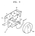
- a mode switch assembly 10 of an automobile includes a housing 20 disposed inside a center facia panel 100 inside the automobile, a circuit board 30 installed inside the housing 20 in which a switch 200 having a shaft 201, a support portion 40 for supporting the circuit board 30 to be separated a predetermined distance from the housing 20, and a knob 202 installed at the shaft 201 to protrude from the center facia panel 100.
- the mode switch assembly 10 includes a breaking portion 50 that allows the knob 202 and the shaft 201 to retreat with respect to the center facia panel 100 as part of the circuit board 30 is broken by an impact/load applied to the shaft 201 from the knob 202.
- the support portion 40 for supporting the circuit board 30 with respect to the housing 20 fixes the circuit board 30 to the housing 20.
- the support portion 40 includes a plurality of bosses 41 protruding from the inner side of the housing 20 to support the circuit board 30 and a plurality of coupling members 43 coupled to the bosses 41 through coupling holes 42 formed in the circuit board 30 to fix the circuit board 30 to the bosses 41.
- the coupling members 43 may be set screws screw-coupled to the bosses 41.
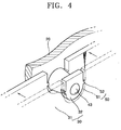
- the breaking portion 50 shown in FIG. 4 allows the knob 202 to be pushed into the center facia panel 100 as part of the circuit board 30 is broken by an impact/load applied in the lengthwise direction of the shaft 201 via the knob 202 and the shaft 201.
- a plurality of slots 51 are formed around each of the coupling holes 42 of the circuit board 30 at a predetermined interval to divide the circuit board 30 into a main body area 31 and a fixing area 32.
- At least one connection portion 52 connecting the main body area 31 and the fixing area 32 is formed between the slots 51.
- the size and number of the slots 51 and the connection portion 52 can be designed to satisfy the restriction regulation of an automobile so that the connection portion 52 can be broken by an impact/load applied through the knob 202 and the shaft 201.
- the breaking portion 50 can be a notch 53 formed between the main body area 31 and the fixing area 32 of the circuit board 30, as shown in FIG. 5.
- the notch 53 can be a groove(s) continuously or discontinuously formed in the circuit board 30.
- FIG. 6 shows another example of the breaking portion 50 in the mode switch assembly of an automobile.
- the breaking portion 50 is formed such that the knob 202 can retreat with respect to the center facia panel 100 by making a portion around the boss 41 of the housing 20 relatively weak so that the portion of the housing 20 can be broken by an impact/load transferred through the knob 202 and the shaft 201.
- at least one slot 56 is formed in the housing 20 around the boss 41 to thus form a housing main body area 21 and a housing boss area 22 . As the slot 56 is formed, the housing main body area 21 and the housing boss area 22 are connected by a connection portion 55.
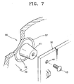
- the breaking portion 50 formed at the housing 20 may be a notch 57 formed around the boss 41, as shown in FIG. 7.
- the notch 57 can be formed by a groove(s) continuously or discontinuously formed in the housing 20 around the boss 41.
- at least one slot 58 is preferably formed at a portion of the housing 20 where the notch 57 is formed, as shown in FIG. 8, so that the housing 20 can be easily broken by an impact/load applied to the boss 41.
- the circuit board 30 is arranged in front of the boss 41 formed on the inner side surface of the housing 20 and fixed to the housing 20 by the coupling member 43. Then, the shaft 201 of the switch 200 installed at the circuit board 30 is arranged to protrude above the center facia panel 100. The knob 202 is coupled to the shaft 201.
- connection portion 52 is broken as the load concentrates on the connection portion 52 which is formed around each of the coupling holes 42 of the circuit board 30 and connects the main body area 31 of the circuit board 30 and the fixing area 32 supported by the bosses 41.
- the circuit board 30 thus retracts by being separated from the bosses 41.
- the knob 202 as well as the shaft 201 is moved together with the circuit board 30 toward the inner side surface of the housing 20.
- the knob 202 is pushed into the center facia panel 100, the impact/load received by a passenger is lowered.
- FIG. 9 shows another preferred embodiment of a mode switch assembly of an automobile of the present invention.
- a mode switch assembly includes a housing 20 disposed in the center facia panel 100 inside the automobile, a circuit board 30 installed in the housing 20 where the switch having the shaft 201 is installed, and a control cover 60 which the shaft 201 penetrates that is fixed to the housing 20, and which includes a front panel.
- the knob 202 is installed on the shaft 201 protruding from the front panel 61.
- a mounting portion 62 for mounting the housing, circuit board and control cover to the center facia panel is provided at either side of the control cover 60.
- a breaking portion 70 is formed on the mounting portion 62 on at least one side of the control cover 60, so that the knob 202 retreats with respect to the center facia panel 100 by an impact/load applied to the knob 202 and the shaft 201.
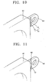
- a plurality of slots 71 are formed in the mounting portion 62 at a predetermined interval and a connection portion 72 to be broken by an impact/load is formed between the slots 71, as shown in FIGS. 9 and 10.
- a breaking portion 80 includes a structurally weak portion at one side of at least one of the main body of the control cover 60 and a mounting portion 62.
- the weak portion 73 may be a notch (not shown) formed continuously or discontinuously around a portion fixed to the housing 20 in the main body of the control cover 60.
- the weak portion 73 may be a notch (or groove) 73 formed continuously or discontinuously at a boundary portion between the mounting portion 62 and the main body of the control cover 60, as shown in FIG. 11.
- both the slot 71 and the notch 73 can be formed in the mounting portion 62.
- the mounting portion 62 of the control cover 60 is broken or the portion where the control cover 60 is coupled to the housing 20 is broken so that the impact/load is lowered. That is, when an impact/load over a predetermined amount is applied to the knob 202, the impact/load is transferred to the control cover 60 though the shaft 201, the circuit board 30, and the housing 20. Thus, the transferred impact/load concentrates on the connection portion 72 formed at the mounting portion 62 and the connection portion 72 is broken.
- the housing 20 and the control cover 60 are separated from the center facia panel 100 and retracted inside the center facia panel 100. Consequently, the knob 202 is pushed into the center facia panel 100 with the housing 20 and the control cover 60 so that the impact/load received by the passenger is lowered.
- a part of the structure is broken to alleviate an impact/load as described.
- electrical/electronic damage to other parts is prevented by the relative movement which lowers an impact/load applied by the knob 202 and damage to the related parts is minimized and durability is improved.
- the impact/load absorbing switch assembly eases the restriction on the impact/load to be taken into consideration at the early stage of design, not only the knob and control cover but also the center facia panel can be freely designed.
- FIGS. 12 and 13 show another embodiment of a mode switch assembly of an automobile not claimed in the present invention.
- a mode switch assembly includes the housing 20 disposed in the center facia panel 100 inside the automobile, a circuit board 30 installed in the housing 20 where the switch having the shaft 201 is installed, and a control cover 60 that the shaft 201 penetrates coupled to the center facia panel 100.
- the control cover 60 is coupled to the center facia panel by mounting portions 62 including slots 71 and connecting portions 72 as in the embodiment of Figures 9 and 10.
- One end portion of the shaft 201 is coupled to a hole 204 formed in a hub 203 of the knob 202 by a coupling unit to be capable of sliding.
- the coupling unit 80 may include a flat surface 81 formed on the outer circumference of the shaft 201 in the lengthwise direction and a rotation prevention portion 82 formed on the inner surface of the hole 204 of the hub 203 to contact the flat surface 81 of the shaft 201.
- a spline may be formed on the outer circumferential surface of the shaft 201 and the inner circumferential surface of the hole 204.
- the shaft 201 and the hub 203 are coupled such that they cannot be separated or slide without applying an external force.
- An impact/load absorbing portion 90 for absorbing an impact/load applied to the knob 202 is installed between the bottom surface of the hole 204 formed in the hub 203 and the end portion of the shaft 201.
- the impact/load absorbing portion 90 may be an elastic member 91 disposed between the bottom surface of the hole 204 and the end portion of the shaft 201.
- the elastic member 91 is a bar formed of a rubber member having a diameter less than that of the shaft 201.
- the elastic member 91 may be a coil spring.
- the elastic support portion 95 for elastically supporting the knob 202 and guiding reciprocation of the knob 202 is provided between the control cover 60 and the knob 202.
- the elastic support portion 95 includes a flange portion 95a circularly formed around the hub 203 on the inner circumferential surface of the knob 202, an inner flange portion 95b formed on the control cover 60 to extend toward the knob 202, and a guide portion 95c installed at the end portion of the inner flange portion 95b for guiding the end portion of the inner flange portion 95b.
- the elastic support portion 95 is not limited by the above-described preferred embodiment and any structure capable of elastically supporting the knob 202 can be adopted.
- the knob 202 In the mode switch assembly of an automobile having the impact/load absorbing apparatus having the above structure, when an impact/load over a predetermined amount is applied to the knob 202, the knob 202 is moved along the shaft 201 by the impact/load. Accordingly, as the knob 202 presses the elastic member 91 located in the hole 204 of the hub 203, the elastic member 91 is bent. As the elastic member 91 is bent, the knob 202 is compressed and moved within a range satisfying the restrictions on the amount of protrusion of the knob. When the external force is removed, the knob 202 is returned to the original position by the elastic support portion 95 and the elastic member 91.
- the guide portion 95c formed at the end portion of the inner flange portion 95b of the control cover 60 is inserted into the inner flange portion 95b of the knob 202 and guides the knob 202 to stably move forward and backward and simultaneously support the knob 202 not to be pushed into the housing 20.
- the knob 202 is moved into the control cover 60 so as to be pushed into the center facia panel 100.
- an impact/load received by a passenger can be lowered. Since the impact/load absorbing portion 90 reduces damage by the knob 202 to other parts as an impact/load is absorbed by the bending of the elastic member 91 and the knob 202 returns to its original state after the impact/load is removed, the damage to the parts can be minimized.
- the breaking portion formed at the circuit board, the housing, or the control cover is broken and the knob is moved.
- the impact/load is lowered and the damage to the passenger can be minimized.
- parts can be prevented from being damaged by the impact/load applied to the knob.
Landscapes
- Engineering & Computer Science (AREA)
- Mechanical Engineering (AREA)
- Switch Cases, Indication, And Locking (AREA)
- Push-Button Switches (AREA)
- Switches With Compound Operations (AREA)
- Instrument Panels (AREA)
- Rotary Switch, Piano Key Switch, And Lever Switch (AREA)
Description
- The present invention relates to a switch assembly of an automobile, and more particularly to a switch assembly having a load absorbing apparatus for absorbing a load applied to a knob of a switch assembly.
- In general, an internal controlling apparatus having air vent nozzles and a plurality of mode switches for operating a radio and an air conditioning apparatus is installed at a center facia panel installed at the central portion of a dashboard of an automobile. A variety of knobs for manipulating the internal controlling apparatus are installed at the mode switches.
- The knobs protrude from the surface of the center facia panel and the heights of the knobs protruding from the surface of the center facia panel are regulated by laws for the safety of a passenger in automobile accidents.
- Thus, the knobs of most mode switches installed at the internal controlling apparatus are designed not to protrude above a regulated height. However, in the case of knobs or protrusions protruding over a predetermined height for the convenience of manipulation for a passenger, when an impact/load of a predetermined amount (38.5 kgf) is applied by a passenger in an automobile accident, the knobs or protrusions are designed to absorb the impact/load by being pushed into the center facia panel to protect the passenger.
- FIG. 1 is a view showing the arrangement of the mode switches installed at the center facia panel. FIG. 2 is a sectional view showing a conventional impact/load absorbing apparatus of a knob protruding over a predetermined height from the surface of the center facia panel.
- Referring to the drawings, a knob impact/load absorbing apparatus for a mode switch of an automobile includes a
housing 1 inserted into acenter facia panel 100 of an automobile and fixed to thecenter facia panel 100, and ashaft 2 installed at thehousing 1 to be capable of rotating and sliding in the lengthwise direction. Aknob 3 protruding from thecenter facia panel 100 is installed at one end portion of theshaft 2. Theshaft 2 is elastically biased toward theknob 3 by abuffer spring 4 installed in thehousing 1. - When an impact/load is applied to the
knob 3 by a passenger in an automobile accident, the impact/load absorbing apparatus of a mode switch having the above structure protects a passenger from injury by absorbing the impact/load as thebuffer spring 4 is compressed. - However, the impact/load absorbing apparatus for a mode switch of an automobile generates noise during rotation of the
shaft 2 since theshaft 2 is elastically supported by thebuffer spring 4. Also, there is lots of restrictions in designing the mode switch. -
Japanese Patent Publication No. Hei 7-201250 -
Japanese Patent Publication Nos. 2000-222974 Hei 8-138480 Japanese Patent Publication No. 8-138480 US-A-5 235 648 discloses another example of load absorbing means for a switch. - To solve the above-described problems, it is an object of the present invention to provide a mode switch assembly of an automobile having an impact/load absorbing apparatus which can protect a passenger by absorbing an impact/load applied to a knob by the passenger in an automobile accident.
- It is another object of the present invention to provide a mode switch assembly of an automobile having an impact/load absorbing apparatus which can reduce noise generated due to manipulation of the switch, improve a sense of manipulation, and ease design restrictions.
- It is yet another object of the present invention to provide a mode switch assembly of an automobile having an impact/load absorbing apparatus which can overcome restrictions relating to the height of a knob protruding from the center facia panel.
- From a first aspect, the present invention provides a load absorbing switch assembly of an automobile, comprising:
- a housing disposed in a center facia panel of an automobile;
- a circuit board installed in the housing, in which a switch having a shaft is installed in a main body area of the circuit board;
- a support portion for supporting the circuit board a predetermined distance from the housing, the support portion fixed to the circuit board at a fixing area;
- a knob installed on the shaft to protrude from the center facia panel; and
- a breaking portion located around the support portion in either the circuit board or the housing for allowing the knob, shaft and at least the main body area of the circuit board, to retract with respect to the center facia panel when the breaking portion is broken by a load applied to the shaft from the knob.
- It is preferred in the present invention that the breaking portion has at least one notch so that the circuit board between the main body area and the fixing area is broken by an impact/load applied from the knob and the shaft.
- It is preferred in the present invention that the support portion comprises a plurality of bosses protruding from the housing and a plurality of coupling members fixing the circuit board to the bosses.
- It is preferred in the present invention that the breaking portion has at least one slot formed at the mounting portion and at least one connection portion to be broken by an impact/load is installed between slots.
- From a further aspect, the invention provides a load absorbing switch assembly of an automobile comprising:
- a housing disposed in a center facia panel of an automobile;
- a circuit board installed in the housing, in which a switch having a shaft is installed on a main body area of the circuit board;
- a support portion for supporting the circuit board to be separated by a predetermined distance from the housing;
- a control cover to which the housing is fixed and that the shaft penetrates, on which a mounting portion coupled to the center facia panel is formed;
- a knob installed at one end portion of the shaft to protrude from the center facia panel; and
- a breaking portion formed on or between at least one side of the control cover and the mounting portion to allow the knob, shaft and main body area of the circuit board to retract with respect to the center facia panel by being broken by a load applied to the knob and the shaft.
- It is preferred in the present invention that the breaking portion has a plurality of slots for weakening the structure of the housing formed around each of the bosses so that the housing around each of the bosses is broken by an impact/load applied from the knob and the shaft.
- Preferred embodiments of the invention will now be described by way of example only, with reference to the accompanying drawings in which:
- FIG. 1 is a perspective view showing a general center facia panel of an automobile;
- FIG. 2 is a sectional view of a conventional mode switch assembly;
- FIG. 3 is an exploded perspective view of a mode switch assembly of an automobile having an impact/load absorbing apparatus according to the present invention;
- FIG. 4 is a magnified perspective view showing an impact/load absorbing portion of FIG. 3;
- FIGS. 5 through 8 are partially cut-away perspective view showing examples of impact/load absorbing portions according to other preferred embodiments;
- FIG. 9 is a partially cut-away perspective view showing another preferred embodiment of a mode switch assembly of an automobile having the impact/load absorbing apparatus of the present invention;
- FIG. 10 is a perspective view showing a mounting portion of a control cover shown in FIG. 9;
- FIG. 11 is a partially cut-away perspective view showing an impact/load absorbing portion according to another preferred embodiment of the present invention;
- FIG. 12 is a partially cut-away perspective view showing another mode switch assembly of an automobile having the impact/load absorbing apparatus; and
- FIG. 13 is a sectional view of a mode switch assembly of an automobile having an impact/load absorbing apparatus shown in FIG. 12.
- In the following description of preferred embodiments of the present invention, the same reference numerals are used for the same elements having the same functions and redundant portions between preferred embodiments will be omitted for clarity.
- A load absorbing switch assembly of an automobile according to the present invention is provided to protect a passenger from a knob protruding from a center facia panel in an automobile accident when there is a need for the knob to protrude from the center facia panel by more than a predetermined restricted height. Since the installation of the mode switch assembly is not limited to a center facia panel, it can be installed at any place in the automobile for example ceiling or door of the automobile.
- FIG. 3 shows a mode switch assembly of an automobile according to a first embodiment of the present invention.
- Referring to the drawings, a
mode switch assembly 10 of an automobile according to the present invention includes ahousing 20 disposed inside acenter facia panel 100 inside the automobile, acircuit board 30 installed inside thehousing 20 in which aswitch 200 having ashaft 201, asupport portion 40 for supporting thecircuit board 30 to be separated a predetermined distance from thehousing 20, and aknob 202 installed at theshaft 201 to protrude from thecenter facia panel 100. Also, themode switch assembly 10 includes a breakingportion 50 that allows theknob 202 and theshaft 201 to retreat with respect to thecenter facia panel 100 as part of thecircuit board 30 is broken by an impact/load applied to theshaft 201 from theknob 202. - The
support portion 40 for supporting thecircuit board 30 with respect to thehousing 20 fixes thecircuit board 30 to thehousing 20. Thesupport portion 40 includes a plurality ofbosses 41 protruding from the inner side of thehousing 20 to support thecircuit board 30 and a plurality ofcoupling members 43 coupled to thebosses 41 throughcoupling holes 42 formed in thecircuit board 30 to fix thecircuit board 30 to thebosses 41. Here, thecoupling members 43 may be set screws screw-coupled to thebosses 41. - The breaking
portion 50 shown in FIG. 4 allows theknob 202 to be pushed into thecenter facia panel 100 as part of thecircuit board 30 is broken by an impact/load applied in the lengthwise direction of theshaft 201 via theknob 202 and theshaft 201. - Referring to the drawing, a plurality of
slots 51 are formed around each of thecoupling holes 42 of thecircuit board 30 at a predetermined interval to divide thecircuit board 30 into amain body area 31 and afixing area 32. At least oneconnection portion 52 connecting themain body area 31 and thefixing area 32 is formed between theslots 51. Here, the size and number of theslots 51 and theconnection portion 52 can be designed to satisfy the restriction regulation of an automobile so that theconnection portion 52 can be broken by an impact/load applied through theknob 202 and theshaft 201. - Alternatively, the breaking
portion 50 can be anotch 53 formed between themain body area 31 and the fixingarea 32 of thecircuit board 30, as shown in FIG. 5. Thenotch 53 can be a groove(s) continuously or discontinuously formed in thecircuit board 30. - FIG. 6 shows another example of the breaking
portion 50 in the mode switch assembly of an automobile. The breakingportion 50 is formed such that theknob 202 can retreat with respect to thecenter facia panel 100 by making a portion around theboss 41 of thehousing 20 relatively weak so that the portion of thehousing 20 can be broken by an impact/load transferred through theknob 202 and theshaft 201. Referring to the drawing, in the breakingportion 50, at least oneslot 56 is formed in thehousing 20 around theboss 41 to thus form a housingmain body area 21 and ahousing boss area 22 . As theslot 56 is formed, the housingmain body area 21 and thehousing boss area 22 are connected by aconnection portion 55. - The breaking
portion 50 formed at thehousing 20 may be anotch 57 formed around theboss 41, as shown in FIG. 7. Thenotch 57 can be formed by a groove(s) continuously or discontinuously formed in thehousing 20 around theboss 41. Here, when thenotch 57 is formed around theboss 41 of thehousing 20, at least oneslot 58 is preferably formed at a portion of thehousing 20 where thenotch 57 is formed, as shown in FIG. 8, so that thehousing 20 can be easily broken by an impact/load applied to theboss 41. - The operation of the mode switch assembly of an automobile having the above-described structure according to the embodiment of Figure 4 is described as follows.
- In the mode switch assembly of the above-described preferred embodiment, the
circuit board 30 is arranged in front of theboss 41 formed on the inner side surface of thehousing 20 and fixed to thehousing 20 by thecoupling member 43. Then, theshaft 201 of theswitch 200 installed at thecircuit board 30 is arranged to protrude above thecenter facia panel 100. Theknob 202 is coupled to theshaft 201. - In an automobile accident, when an impact/load over a predetermined amount defined by corresponding automobile protrusion restriction regulations is applied by a passenger to the
knob 202 protruding above thecenter facia panel 100, the impact/load is transferred to thecircuit board 30 via theshaft 201. Theconnection portion 52 is broken as the load concentrates on theconnection portion 52 which is formed around each of the coupling holes 42 of thecircuit board 30 and connects themain body area 31 of thecircuit board 30 and the fixingarea 32 supported by thebosses 41. Thecircuit board 30 thus retracts by being separated from thebosses 41. - Then, the
knob 202 as well as theshaft 201 is moved together with thecircuit board 30 toward the inner side surface of thehousing 20. Thus, as theknob 202 is pushed into thecenter facia panel 100, the impact/load received by a passenger is lowered. - When the
slot 56 and theconnection portion 55 are formed around theboss 41, as shown in FIG. 6, or thenotch 57 is formed as shown in FIGS. 7 and 8, the impact/load applied to theknob 202 and theshaft 201 is transferred to theboss 41 via thecircuit board 30. Thus, as the load concentrates on the portion where theconnection portion 55 or thenotch 57 is formed, which is relatively weak, theconnection portion 55 or thenotch 57 is broken. As a result, thecircuit board 30 which is coupled to theboss 41 is separated from thehousing 20 and retracts, so that theknob 202 is pushed into thecenter facia panel 100 and the impact/load received by the passenger is lowered. - FIG. 9 shows another preferred embodiment of a mode switch assembly of an automobile of the present invention.
- Referring to Figure 9, a mode switch assembly according to another preferred embodiment of the present invention includes a
housing 20 disposed in thecenter facia panel 100 inside the automobile, acircuit board 30 installed in thehousing 20 where the switch having theshaft 201 is installed, and acontrol cover 60 which theshaft 201 penetrates that is fixed to thehousing 20, and which includes a front panel. Theknob 202 is installed on theshaft 201 protruding from thefront panel 61. - A mounting
portion 62 for mounting the housing, circuit board and control cover to the center facia panel is provided at either side of thecontrol cover 60. A breakingportion 70 is formed on the mountingportion 62 on at least one side of thecontrol cover 60, so that theknob 202 retreats with respect to thecenter facia panel 100 by an impact/load applied to theknob 202 and theshaft 201. - In the breaking
portion 70, a plurality ofslots 71 are formed in the mountingportion 62 at a predetermined interval and aconnection portion 72 to be broken by an impact/load is formed between theslots 71, as shown in FIGS. 9 and 10. - Another preferred embodiment of a breaking
portion 80 includes a structurally weak portion at one side of at least one of the main body of thecontrol cover 60 and a mountingportion 62. Theweak portion 73 may be a notch (not shown) formed continuously or discontinuously around a portion fixed to thehousing 20 in the main body of thecontrol cover 60. Theweak portion 73 may be a notch (or groove) 73 formed continuously or discontinuously at a boundary portion between the mountingportion 62 and the main body of thecontrol cover 60, as shown in FIG. 11. Here, both theslot 71 and thenotch 73 can be formed in the mountingportion 62. - In the mode switch assembly of an automobile having the above structure according to the above-described preferred embodiment of the present invention, when an impact/load over a predetermined amount is applied to the
knob 202, the mountingportion 62 of thecontrol cover 60 is broken or the portion where thecontrol cover 60 is coupled to thehousing 20 is broken so that the impact/load is lowered. That is, when an impact/load over a predetermined amount is applied to theknob 202, the impact/load is transferred to thecontrol cover 60 though theshaft 201, thecircuit board 30, and thehousing 20. Thus, the transferred impact/load concentrates on theconnection portion 72 formed at the mountingportion 62 and theconnection portion 72 is broken. As a result, thehousing 20 and thecontrol cover 60 are separated from thecenter facia panel 100 and retracted inside thecenter facia panel 100. Consequently, theknob 202 is pushed into thecenter facia panel 100 with thehousing 20 and thecontrol cover 60 so that the impact/load received by the passenger is lowered. - In the embodiments of the invention, a part of the structure is broken to alleviate an impact/load as described. Thus electrical/electronic damage to other parts is prevented by the relative movement which lowers an impact/load applied by the
knob 202 and damage to the related parts is minimized and durability is improved. Also, since the impact/load absorbing switch assembly eases the restriction on the impact/load to be taken into consideration at the early stage of design, not only the knob and control cover but also the center facia panel can be freely designed. - FIGS. 12 and 13 show another embodiment of a mode switch assembly of an automobile not claimed in the present invention.
- Referring to the drawings, a mode switch assembly according to yet another preferred embodiment of the present invention includes the
housing 20 disposed in thecenter facia panel 100 inside the automobile, acircuit board 30 installed in thehousing 20 where the switch having theshaft 201 is installed, and acontrol cover 60 that theshaft 201 penetrates coupled to thecenter facia panel 100. The control cover 60 is coupled to the center facia panel by mountingportions 62 includingslots 71 and connectingportions 72 as in the embodiment of Figures 9 and 10. One end portion of theshaft 201 is coupled to ahole 204 formed in ahub 203 of theknob 202 by a coupling unit to be capable of sliding. Thecoupling unit 80 may include aflat surface 81 formed on the outer circumference of theshaft 201 in the lengthwise direction and arotation prevention portion 82 formed on the inner surface of thehole 204 of thehub 203 to contact theflat surface 81 of theshaft 201. Here, a spline may be formed on the outer circumferential surface of theshaft 201 and the inner circumferential surface of thehole 204. Preferably, theshaft 201 and thehub 203 are coupled such that they cannot be separated or slide without applying an external force. - An impact/
load absorbing portion 90 for absorbing an impact/load applied to theknob 202 is installed between the bottom surface of thehole 204 formed in thehub 203 and the end portion of theshaft 201. The impact/load absorbing portion 90 may be anelastic member 91 disposed between the bottom surface of thehole 204 and the end portion of theshaft 201. Theelastic member 91 is a bar formed of a rubber member having a diameter less than that of theshaft 201. Theelastic member 91 may be a coil spring. - An
elastic support portion 95 for elastically supporting theknob 202 and guiding reciprocation of theknob 202 is provided between thecontrol cover 60 and theknob 202. Theelastic support portion 95 includes aflange portion 95a circularly formed around thehub 203 on the inner circumferential surface of theknob 202, aninner flange portion 95b formed on thecontrol cover 60 to extend toward theknob 202, and aguide portion 95c installed at the end portion of theinner flange portion 95b for guiding the end portion of theinner flange portion 95b. Theelastic support portion 95 is not limited by the above-described preferred embodiment and any structure capable of elastically supporting theknob 202 can be adopted. - In the mode switch assembly of an automobile having the impact/load absorbing apparatus having the above structure, when an impact/load over a predetermined amount is applied to the
knob 202, theknob 202 is moved along theshaft 201 by the impact/load. Accordingly, as theknob 202 presses theelastic member 91 located in thehole 204 of thehub 203, theelastic member 91 is bent. As theelastic member 91 is bent, theknob 202 is compressed and moved within a range satisfying the restrictions on the amount of protrusion of the knob. When the external force is removed, theknob 202 is returned to the original position by theelastic support portion 95 and theelastic member 91. Theguide portion 95c formed at the end portion of theinner flange portion 95b of thecontrol cover 60 is inserted into theinner flange portion 95b of theknob 202 and guides theknob 202 to stably move forward and backward and simultaneously support theknob 202 not to be pushed into thehousing 20. - Then, the
knob 202 is moved into thecontrol cover 60 so as to be pushed into thecenter facia panel 100. Thus, an impact/load received by a passenger can be lowered. Since the impact/load absorbing portion 90 reduces damage by theknob 202 to other parts as an impact/load is absorbed by the bending of theelastic member 91 and theknob 202 returns to its original state after the impact/load is removed, the damage to the parts can be minimized. - As described above, in the mode switch assembly of an automobile according to the present invention, when an impact/load over a predetermined amount is applied to the knob, the breaking portion formed at the circuit board, the housing, or the control cover is broken and the knob is moved. Thus, the impact/load is lowered and the damage to the passenger can be minimized. Also, parts can be prevented from being damaged by the impact/load applied to the knob.
- While this invention has been particularly shown and described with reference to preferred embodiments thereof, it will be understood by those skilled in the art that various changes in form and details may be made therein without departing from the scope of the invention as defined by the appended claims.
Claims (14)
- A load absorbing switch assembly (10) of an automobile, comprising:a housing (20) disposed in a center facia panel (100) of an automobile;a support portion (40) for supporting a circuit board (30) a predetermined distance from the housing (20), the support portion fixed to the circuit board (30) at a fixing area (32) ;a knob (202) installed on the shaft (201) to protrude from the center facia panel (100), characterised in that :the circuit board (30) is installed in the housing (20), in which a switch (200) having a shaft (201) is installed in a main body area (31) of the circuit board (30), anda breaking portion is located around the support portion in either the circuit board (30) or the housing (20) for allowing the knob (202), shaft (201) and at least the main body area (31) of the circuit boards (30), to retract with respect to the center facia panel (100) when the breaking portion is broken by a load applied to the shaft (201) from the knob (202).
- A switch assembly as claimed in claim 1, wherein the breaking portion comprises at least one notch (53) formed in the circuit board between the main body area (31) and the fixing area (32) so that the circuit board (30) is broken by a load applied from the knob (202) and the shaft (201).
- A switch assembly as claimed in claim 1, wherein the breaking portion comprises at least one slot (51) formed in the circuit board (30) between the main body area (31) and the fixing area (32) so that the circuit board is broken by a load applied from the knob (202) and the shaft (201).
- A switch assembly as claimed in claim 1 or 3, wherein the breaking portion comprises at least one groove formed between the main body area (31) and the fixing area (32) so that the circuit board (30) is broken by a load applied from the knob (202) and the shaft (201).
- A switch assembly as claimed in claim 1, wherein the support portion (40) comprises a plurality of bosses (41) protruding from the housing (20) and a plurality of coupling members (43) fixing the circuit board (30) to the bosses.
- A switch assembly as claimed in claim 5, wherein the breaking portion comprises a plurality of slots (56) formed in the housing (20) around each of the bosses (41) for weakening the structure of the housing so that the housing around each of the bosses is broken by a load applied from the knob (202) and the shaft (201).
- A switch assembly as claimed in claim 5, wherein the breaking portion comprises a plurality of slots (51) continuously formed at a predetermined interval around a portion in the circuit board (30) where the circuit board is coupled to the bosses (41).
- A switch assembly as claimed in claim 1, wherein the breaking portions comprises at least one notch (57) or slot (56) formed in the housing (20) so that the housing is broken by a load applied from the knob (202) and the shaft (201).
- A load absorbing switch assembly (10) of an automobile comprising:a housing (20) disposed in a center facia panel (100) of an automobile;a support portion (40) for supporting a circuit board (30) to be separated by a predetermined distance from the housing (20).a control cover (60) to which the housing (20) is fixed and that the shaft (201) penetrates, on which a mounting portion (62) coupled to the center facia panel (100) is formed;a knob (202) installed at one end portion of the shaft (201) to protrude from the center facia panel (100), characterised in that:the circuit board (30) is installed in the housing (20), in which a switch (200) having a shaft (201) is installed on a main body area (31) of the circuit board (30), anda breaking portion is formed on or between at least one side of the control cover (60) and the mounting portion (62) to allow the knob (202), shaft (201) and main body area (31) of the circuit board (20) to retract with respect to the center facia panel (100) by being broken by a load applied to the knob (202) and the shaft (201).
- A switch assembly as claimed in claim 9, wherein the breaking portion comprises at least one slot (71) formed at the mounting portion (62) and at least one connection portion (72) to be broken by a load is provided adjacent the slot.
- A switch assembly as claimed in claim 9, wherein the breaking portion comprises at least one notch (73) formed at the boundary portion between the mounting portion (62) and the control cover (60).
- A switch assembly as claimed in claim 9, wherein the breaking portion comprises at least one groove formed at the boundary portion between the mounting portion (62) and the control cover (60).
- A switch assembly as claimed in claim 9, wherein the breaking portion comprises at least one groove formed in the control cover (60) at the boundary portion between the housing (20) and the control cover (60).
- A load absorbing switch assembly as claimed in claim 1 wherein the assembly further comprises:a control cover (60) to which the housing is fixed and that the shaft penetrates, on which a mounting portion (62) coupled to the center facia panel is formed; andan auxiliary breaking portion installed on at least one side of the control cover and the mounting portion for allowing the knob to retract with respect to the center facia panel by a load applied to the knob and the shaft.
Applications Claiming Priority (4)
| Application Number | Priority Date | Filing Date | Title |
|---|---|---|---|
| KR2001017914 | 2001-04-04 | ||
| KR20010017914 | 2001-04-04 | ||
| KR2001086737 | 2001-12-28 | ||
| KR10-2001-0086737A KR100461979B1 (en) | 2001-04-04 | 2001-12-28 | Impact absorbing structure of knob for mode switch in vehicle |
Publications (3)
| Publication Number | Publication Date |
|---|---|
| EP1248274A2 EP1248274A2 (en) | 2002-10-09 |
| EP1248274A3 EP1248274A3 (en) | 2004-09-08 |
| EP1248274B1 true EP1248274B1 (en) | 2007-06-13 |
Family
ID=26638951
Family Applications (1)
| Application Number | Title | Priority Date | Filing Date |
|---|---|---|---|
| EP02252444A Expired - Lifetime EP1248274B1 (en) | 2001-04-04 | 2002-04-04 | Switch assembly of an automobile having a load absorbing apparatus |
Country Status (4)
| Country | Link |
|---|---|
| US (1) | US6696769B2 (en) |
| EP (1) | EP1248274B1 (en) |
| JP (1) | JP3595858B2 (en) |
| DE (1) | DE60220574T2 (en) |
Families Citing this family (26)
| Publication number | Priority date | Publication date | Assignee | Title |
|---|---|---|---|---|
| KR100461979B1 (en) * | 2001-04-04 | 2004-12-14 | 한라공조주식회사 | Impact absorbing structure of knob for mode switch in vehicle |
| US6696769B2 (en) * | 2001-04-04 | 2004-02-24 | Halla Climate Control Corporation | Mode switch assembly of automobile having impact/load absorbing apparatus |
| FR2843270A1 (en) * | 2002-08-02 | 2004-02-06 | Bruno Coissac | Printed circuit component deadening/fixing mechanism having flexible section clamp between two end sections reducing risk printed circuit track microscopic breakage. |
| KR100983328B1 (en) * | 2003-05-20 | 2010-09-20 | 한라공조주식회사 | Heater Control Switch Assembly Structure of Vehicle |
| KR100983329B1 (en) | 2003-05-23 | 2010-09-20 | 한라공조주식회사 | Impact absorbing knob for mode switch in vehicle |
| DE10357138B3 (en) * | 2003-12-06 | 2005-06-23 | Behr Gmbh & Co. Kg | Operating and / or display device for the interior of a vehicle, in particular vehicle control unit |
| JP2006151186A (en) | 2004-11-29 | 2006-06-15 | Alps Electric Co Ltd | Operating panel unit |
| JP4209382B2 (en) | 2004-12-06 | 2009-01-14 | アルプス電気株式会社 | Panel unit |
| US20070138833A1 (en) * | 2005-12-20 | 2007-06-21 | Lear Corporation | Energy absorption device |
| US7648184B2 (en) * | 2006-03-27 | 2010-01-19 | Honda Motor Co., Ltd. | Audio component mounting system |
| US7479607B2 (en) | 2006-07-28 | 2009-01-20 | Bose Corporation | Control knob with safety feature |
| JP2008137476A (en) * | 2006-12-01 | 2008-06-19 | Mazda Motor Corp | Vehicle control device |
| EP2095023B1 (en) * | 2006-12-18 | 2010-11-17 | Arçelik Anonim Sirketi | A household appliance |
| JP5135934B2 (en) * | 2007-07-27 | 2013-02-06 | パナソニック株式会社 | Vehicle switch |
| JP5292903B2 (en) * | 2008-04-17 | 2013-09-18 | パナソニック株式会社 | Switch device for vehicle |
| KR101484700B1 (en) * | 2008-12-09 | 2015-01-21 | 한라비스테온공조 주식회사 | Mode switch assembly for vehicle |
| KR20130081064A (en) * | 2012-01-06 | 2013-07-16 | 현대자동차주식회사 | Air conditioner controlling device for vehicle |
| JP6150155B2 (en) * | 2012-06-01 | 2017-06-21 | 株式会社豊田自動織機 | Vehicle mounting device mounting unit |
| KR20140025245A (en) * | 2012-08-22 | 2014-03-04 | 현대모비스 주식회사 | Knob assembly of electronic equipment for vehicle |
| JP5880468B2 (en) | 2013-02-05 | 2016-03-09 | マツダ株式会社 | Dropout structure for vehicle operation switch |
| JP5990549B2 (en) | 2014-01-30 | 2016-09-14 | 株式会社東海理化電機製作所 | Switch drop-off structure |
| JP6398558B2 (en) * | 2014-02-13 | 2018-10-03 | 株式会社デンソー | In-vehicle device |
| CN106564352B (en) * | 2016-10-21 | 2019-06-14 | 奇瑞汽车股份有限公司 | A kind of automobile manual air-conditioning control panel knob collapsing structure |
| CN110178455A (en) * | 2017-01-24 | 2019-08-27 | 三菱电机株式会社 | Bump dropping structure and electronic equipment including bump dropping structure |
| DE102018216879A1 (en) | 2018-10-01 | 2020-04-02 | Eaton Intelligent Power Limited | Protective collar for actuators, especially switches |
| US10959323B1 (en) | 2019-09-06 | 2021-03-23 | Performance Motion Devices, Inc. | Over-torque protection features for mounting an electronic device to a heat dissipation object |
Family Cites Families (28)
| Publication number | Priority date | Publication date | Assignee | Title |
|---|---|---|---|---|
| FR1523308A (en) * | 1967-03-20 | 1968-05-03 | Anti-shock device applicable to all protruding devices mounted on the dashboard of a motor vehicle or the like | |
| DE6933661U (en) * | 1969-08-12 | 1969-12-04 | Rau Swf Autozubehoer | DEVICE FOR FASTENING AN EQUIPMENT, IN PARTICULAR A SWITCH OR THE SAME, IN THE DASHBOARD OF A MOTOR VEHICLE. |
| FR2065492A6 (en) * | 1969-10-24 | 1971-07-30 | Borletti Spa | |
| DE2253559A1 (en) * | 1972-11-02 | 1974-05-16 | Porsche Ag | DEVICE FOR FASTENING CONTROL ELEMENTS |
| US4051916A (en) * | 1975-12-22 | 1977-10-04 | Nissan Motor Company, Limited | Apparatus for mounting instrument to instrument panel in motor vehicle |
| DE7820391U1 (en) * | 1978-07-06 | 1979-10-25 | Siemens Ag, 1000 Berlin Und 8000 Muenchen | Portable electrical device with a built-in printed circuit board |
| DE2952057A1 (en) * | 1979-12-22 | 1981-06-25 | Gebr. Happich Gmbh, 5600 Wuppertal | CONTROL HEAD, IN PARTICULAR FOR WINDOW CRANKS OF VEHICLES |
| JPS58164441A (en) * | 1982-03-24 | 1983-09-29 | Suzuki Motor Co Ltd | Safety device for operating lever of automobile instrument panel |
| US4903987A (en) * | 1987-05-04 | 1990-02-27 | General Electric Company | Energy absorbing automotive instrument panel |
| JPH0467301U (en) * | 1990-10-22 | 1992-06-15 | ||
| US5111620A (en) * | 1990-12-24 | 1992-05-12 | General Motors Corporation | Energy absorbing modular door |
| JPH0636168A (en) | 1992-07-13 | 1994-02-10 | Mitsubishi Electric Corp | Security device |
| FR2698459B1 (en) * | 1992-11-20 | 1994-12-30 | Renault | Retractable button for controlling a rotating support shaft. |
| US5306884A (en) * | 1992-12-30 | 1994-04-26 | Itt Corporation | Impact resistant switch knob |
| JP3424849B2 (en) | 1994-01-14 | 2003-07-07 | 株式会社安川電機 | Manipulator compliance controller |
| US5738694A (en) * | 1994-01-21 | 1998-04-14 | Covol Technologies, Inc. | Process for recovering iron from iron-containing material |
| JPH08138480A (en) | 1994-11-02 | 1996-05-31 | Matsushita Electric Ind Co Ltd | switch |
| US5826907A (en) * | 1996-02-20 | 1998-10-27 | Nissan Motor Co., Ltd. | Vehicle energy absorbing structure |
| JPH1021782A (en) * | 1996-07-04 | 1998-01-23 | Tokai Rika Co Ltd | Electric switch device |
| JP3983836B2 (en) * | 1996-08-20 | 2007-09-26 | 株式会社東海理化電機製作所 | Shift lever device |
| US5857242A (en) * | 1996-11-19 | 1999-01-12 | Illinois Tool Works Inc. | Control knob |
| US6073312A (en) * | 1997-02-10 | 2000-06-13 | Delco Electronics Corporation | Collapsible knob assembly and retaining spring therefor |
| JP4297996B2 (en) * | 1997-12-26 | 2009-07-15 | 三菱電機株式会社 | Operating device |
| DE19964133A1 (en) * | 1999-11-22 | 2001-06-13 | Preh Elektro Feinmechanik | Rotary switch |
| DE10054588A1 (en) * | 2000-11-03 | 2002-05-08 | Siemens Ag | Electronic device intended for a motor vehicle |
| US6696769B2 (en) * | 2001-04-04 | 2004-02-24 | Halla Climate Control Corporation | Mode switch assembly of automobile having impact/load absorbing apparatus |
| JP2003040039A (en) * | 2001-07-30 | 2003-02-13 | Daihatsu Motor Co Ltd | Glove box structure |
| US6598365B2 (en) * | 2001-10-12 | 2003-07-29 | Carl J. Abraham | Impact and energy absorbing product for floors, walls, and other flat surfaces |
-
2002
- 2002-04-03 US US10/114,437 patent/US6696769B2/en not_active Expired - Lifetime
- 2002-04-04 JP JP2002102421A patent/JP3595858B2/en not_active Expired - Lifetime
- 2002-04-04 DE DE60220574T patent/DE60220574T2/en not_active Expired - Lifetime
- 2002-04-04 EP EP02252444A patent/EP1248274B1/en not_active Expired - Lifetime
Also Published As
| Publication number | Publication date |
|---|---|
| JP3595858B2 (en) | 2004-12-02 |
| EP1248274A3 (en) | 2004-09-08 |
| US20020145337A1 (en) | 2002-10-10 |
| EP1248274A2 (en) | 2002-10-09 |
| DE60220574D1 (en) | 2007-07-26 |
| DE60220574T2 (en) | 2008-02-21 |
| US6696769B2 (en) | 2004-02-24 |
| JP2003011744A (en) | 2003-01-15 |
Similar Documents
| Publication | Publication Date | Title |
|---|---|---|
| US6696769B2 (en) | Mode switch assembly of automobile having impact/load absorbing apparatus | |
| EP1422733B1 (en) | Push button assembly | |
| JP2940434B2 (en) | Impact energy absorbing structure of vehicle seat belt device | |
| US7225701B2 (en) | Locking device having an actuating lever for an adjustable steering column | |
| KR100461979B1 (en) | Impact absorbing structure of knob for mode switch in vehicle | |
| JP2008041654A (en) | Switch for vehicle | |
| US5280956A (en) | Steering column supporting structure of automotive vehicle | |
| EP2040274A1 (en) | Switch for vehicle | |
| US8464606B2 (en) | Shift operation device | |
| KR100519231B1 (en) | Horn switch assembly | |
| CN104364111B (en) | Car-mounted device installation unit | |
| EP1764812B1 (en) | In-vehicle knob switch device | |
| KR100983329B1 (en) | Impact absorbing knob for mode switch in vehicle | |
| JP2006066288A (en) | Operating mechanism | |
| KR101005205B1 (en) | Rotary push button switch | |
| JP2001266704A (en) | Knob apparatus | |
| US7180024B2 (en) | Operating device | |
| US6849816B2 (en) | Vehicle steering wheel | |
| JP2012208821A (en) | Knob device | |
| KR101040327B1 (en) | Dual rotary push switch | |
| US7038921B2 (en) | Electronic apparatus | |
| JP6798450B2 (en) | Steering wheel | |
| KR100926934B1 (en) | Control Panel Assembly for Air Conditioning Units | |
| KR102484864B1 (en) | Rotary Button Assembly | |
| JP2008234934A (en) | Switch device |
Legal Events
| Date | Code | Title | Description |
|---|---|---|---|
| PUAI | Public reference made under article 153(3) epc to a published international application that has entered the european phase |
Free format text: ORIGINAL CODE: 0009012 |
|
| 17P | Request for examination filed |
Effective date: 20020425 |
|
| AK | Designated contracting states |
Kind code of ref document: A2 Designated state(s): AT BE CH CY DE DK ES FI FR GB GR IE IT LI LU MC NL PT SE TR |
|
| AX | Request for extension of the european patent |
Free format text: AL;LT;LV;MK;RO;SI |
|
| PUAL | Search report despatched |
Free format text: ORIGINAL CODE: 0009013 |
|
| AK | Designated contracting states |
Kind code of ref document: A3 Designated state(s): AT BE CH CY DE DK ES FI FR GB GR IE IT LI LU MC NL PT SE TR |
|
| AX | Request for extension of the european patent |
Extension state: AL LT LV MK RO SI |
|
| AKX | Designation fees paid |
Designated state(s): DE FR GB IT PT SE |
|
| GRAP | Despatch of communication of intention to grant a patent |
Free format text: ORIGINAL CODE: EPIDOSNIGR1 |
|
| RIN1 | Information on inventor provided before grant (corrected) |
Inventor name: CHUN, TAE-SOO Inventor name: LEE, JEONG-YEOP Inventor name: YUN, SEUNG-HYUN |
|
| GRAS | Grant fee paid |
Free format text: ORIGINAL CODE: EPIDOSNIGR3 |
|
| GRAA | (expected) grant |
Free format text: ORIGINAL CODE: 0009210 |
|
| AK | Designated contracting states |
Kind code of ref document: B1 Designated state(s): DE FR GB IT PT SE |
|
| REG | Reference to a national code |
Ref country code: GB Ref legal event code: FG4D |
|
| REF | Corresponds to: |
Ref document number: 60220574 Country of ref document: DE Date of ref document: 20070726 Kind code of ref document: P |
|
| PG25 | Lapsed in a contracting state [announced via postgrant information from national office to epo] |
Ref country code: SE Free format text: LAPSE BECAUSE OF FAILURE TO SUBMIT A TRANSLATION OF THE DESCRIPTION OR TO PAY THE FEE WITHIN THE PRESCRIBED TIME-LIMIT Effective date: 20070913 |
|
| ET | Fr: translation filed | ||
| PG25 | Lapsed in a contracting state [announced via postgrant information from national office to epo] |
Ref country code: PT Free format text: LAPSE BECAUSE OF FAILURE TO SUBMIT A TRANSLATION OF THE DESCRIPTION OR TO PAY THE FEE WITHIN THE PRESCRIBED TIME-LIMIT Effective date: 20071113 |
|
| PLBE | No opposition filed within time limit |
Free format text: ORIGINAL CODE: 0009261 |
|
| STAA | Information on the status of an ep patent application or granted ep patent |
Free format text: STATUS: NO OPPOSITION FILED WITHIN TIME LIMIT |
|
| 26N | No opposition filed |
Effective date: 20080314 |
|
| REG | Reference to a national code |
Ref country code: DE Ref legal event code: R082 Ref document number: 60220574 Country of ref document: DE Representative=s name: EISENFUEHR, SPEISER & PARTNER, DE |
|
| REG | Reference to a national code |
Ref country code: FR Ref legal event code: CD Owner name: HALLA VISTEON CLIMATE CONTROL CORPORATION Effective date: 20130827 |
|
| REG | Reference to a national code |
Ref country code: DE Ref legal event code: R082 Ref document number: 60220574 Country of ref document: DE Representative=s name: EISENFUEHR SPEISER PATENTANWAELTE RECHTSANWAEL, DE Effective date: 20130910 Ref country code: DE Ref legal event code: R081 Ref document number: 60220574 Country of ref document: DE Owner name: HANON SYSTEMS, KR Free format text: FORMER OWNER: HALLA CLIMATE CONTROL CORP., DAEJEON, KR Effective date: 20130910 Ref country code: DE Ref legal event code: R081 Ref document number: 60220574 Country of ref document: DE Owner name: HALLA VISTEON CLIMATE CONTROL CORP., KR Free format text: FORMER OWNER: HALLA CLIMATE CONTROL CORP., DAEJEON, KR Effective date: 20130910 Ref country code: DE Ref legal event code: R082 Ref document number: 60220574 Country of ref document: DE Representative=s name: EISENFUEHR, SPEISER & PARTNER, DE Effective date: 20130910 |
|
| REG | Reference to a national code |
Ref country code: FR Ref legal event code: PLFP Year of fee payment: 15 |
|
| REG | Reference to a national code |
Ref country code: DE Ref legal event code: R082 Ref document number: 60220574 Country of ref document: DE Representative=s name: EISENFUEHR SPEISER PATENTANWAELTE RECHTSANWAEL, DE Ref country code: DE Ref legal event code: R081 Ref document number: 60220574 Country of ref document: DE Owner name: HANON SYSTEMS, KR Free format text: FORMER OWNER: HALLA VISTEON CLIMATE CONTROL CORP., DAEJEON, KR |
|
| REG | Reference to a national code |
Ref country code: FR Ref legal event code: CD Owner name: HANON SYSTEMS Effective date: 20161212 |
|
| REG | Reference to a national code |
Ref country code: FR Ref legal event code: PLFP Year of fee payment: 16 |
|
| REG | Reference to a national code |
Ref country code: FR Ref legal event code: PLFP Year of fee payment: 17 |
|
| PGFP | Annual fee paid to national office [announced via postgrant information from national office to epo] |
Ref country code: FR Payment date: 20210310 Year of fee payment: 20 Ref country code: IT Payment date: 20210310 Year of fee payment: 20 |
|
| PGFP | Annual fee paid to national office [announced via postgrant information from national office to epo] |
Ref country code: GB Payment date: 20210317 Year of fee payment: 20 |
|
| PGFP | Annual fee paid to national office [announced via postgrant information from national office to epo] |
Ref country code: DE Payment date: 20210316 Year of fee payment: 20 |
|
| REG | Reference to a national code |
Ref country code: DE Ref legal event code: R071 Ref document number: 60220574 Country of ref document: DE |
|
| REG | Reference to a national code |
Ref country code: GB Ref legal event code: PE20 Expiry date: 20220403 |
|
| PG25 | Lapsed in a contracting state [announced via postgrant information from national office to epo] |
Ref country code: GB Free format text: LAPSE BECAUSE OF EXPIRATION OF PROTECTION Effective date: 20220403 |