EP1247731A2 - Lager zur begrenzt drehbeweglichen Lagerung von Bauteilen - Google Patents
Lager zur begrenzt drehbeweglichen Lagerung von Bauteilen Download PDFInfo
- Publication number
- EP1247731A2 EP1247731A2 EP02006974A EP02006974A EP1247731A2 EP 1247731 A2 EP1247731 A2 EP 1247731A2 EP 02006974 A EP02006974 A EP 02006974A EP 02006974 A EP02006974 A EP 02006974A EP 1247731 A2 EP1247731 A2 EP 1247731A2
- Authority
- EP
- European Patent Office
- Prior art keywords
- bearing
- rotating body
- rotating
- elastomer
- intermediate element
- Prior art date
- Legal status (The legal status is an assumption and is not a legal conclusion. Google has not performed a legal analysis and makes no representation as to the accuracy of the status listed.)
- Granted
Links
Images


Classifications
-
- B—PERFORMING OPERATIONS; TRANSPORTING
- B62—LAND VEHICLES FOR TRAVELLING OTHERWISE THAN ON RAILS
- B62K—CYCLES; CYCLE FRAMES; CYCLE STEERING DEVICES; RIDER-OPERATED TERMINAL CONTROLS SPECIALLY ADAPTED FOR CYCLES; CYCLE AXLE SUSPENSIONS; CYCLE SIDE-CARS, FORECARS, OR THE LIKE
- B62K25/00—Axle suspensions
- B62K25/04—Axle suspensions for mounting axles resiliently on cycle frame or fork
- B62K25/28—Axle suspensions for mounting axles resiliently on cycle frame or fork with pivoted chain-stay
- B62K25/30—Axle suspensions for mounting axles resiliently on cycle frame or fork with pivoted chain-stay pivoted on pedal crank shelf
Definitions
- the invention relates to a bearing for the limited rotationally movable mounting of components, in particular according to the rear swing arm of a bicycle in the bicycle frame Preamble of claim 1.
- a bicycle with a spring device is known from DE 197 45 380 A1 has at least one torsion spring, which has an outer body and one in this has rotatably mounted inner part. The outer body and the inner part are each connected to a bicycle part.
- a bicycle is pivotable with a pedal crank axis Rear wheel described, in which the rear wheel through a starting from its hub U-shaped bracket made pivotable about the longitudinal axis of the crank bearing and is cushioned against the bicycle frame.
- a concentric to the crank bearing and connected to the bicycle frame Rubber torsion spring for use comes a concentric to the crank bearing and connected to the bicycle frame Rubber torsion spring for use.
- the aforementioned solution is suitable for short spring travel, but is subject to Permanent wear an increased wear.
- the invention is therefore based on the object of a bearing in particular for the To develop the rear swing arm of a bicycle with a simple structure durable and can be used in a comparatively large range of rotation angles.
- the intermediate element of the bearing mentioned in the introduction has an axial one and a radial component that merge and form a layer, such that a direct contact between the bearing body and the rotating body also at dynamic load on the bearing is avoided.
- the intermediate element ensures one constant distance between the bearing body and the rotating body.
- the invention is associated with the advantage that rotation of the parts of the bearing to each other over a large range of rotation angle is possible without negative influence on the durability of the bearing.
- the bearing is also characterized by high transverse rigidity from what an application for example for storage, suspension and damping the Rear wheel swing arm of a bicycle with exact tracking is possible.
- it is the radially stretched one Intermediate element around an elastomer layer that links the required Elastic properties with a damping component allowed. Should the Material stress within the elastomer layer when the Stock components are equalized to each other, it is advantageously provided that the thickness of the elastomer layer with increasing distance from the storage center increases.
- the bearing body and the rotating body can be designed so as to correspond to each other be a wavy elastomer layer deviating from a flat layer arises. Such a measure creates the possibility of the single-spring characteristic to influence and a progressive increase in compression in to achieve the reaction force caused by the elastomer compound.
- the elastomer layer runs essentially radially and away from the storage center Essentially axially close to the bearing center, a balanced torsional behavior of the Bearings are connected with a high shear stability.
- Another qualitative Improvement in the bearing properties occurs when another bearing body or there are two elastomer layers between the rotating body and the bearing bodies. It is also expedient to have a symmetrical arrangement of the elastomer layers to each other, based on the inner body designed as a bearing body or rotating body of the camp.
- a device for generating a preload is provided in the elastomer layer.
- the spring force characteristic can be specifically influenced.
- a threaded bushing can be used as a device for generating the preload come, the axial change in length serves to adjust the degree of preload.
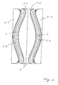
- the bearing according to the invention shown in Fig. 1 consists of a bearing body 1, a Rotary body 2 and one, a limited rotational movement between the bodies 1, 2nd enabling intermediate element in the form of an elastomer layer 3.
- the elastomer layer 3 comprises an essentially axially extending region 3.1 and a region 3.1 Radially extending area 3.2. The latter extends to the end faces 4.5 of the bearing body 1 and the rotating body 2, so that a direct contact between the bearing body 1 and rotating body 2 is excluded and a bias by axial force the elastomer layer 3 can be achieved.
- the angle of rotation sector and the force curve in this angle of rotation sector is the radial one Area 3.2 embedded in a wave shape between the bearing body 1 and the rotating body 2. Over a Change in the waveform caused, for example, by a change in the radius of curvature the wave contour visible from the outside is possible, the size of the angle of rotation sector and the force characteristic curve.
- Rubber is preferably used as the base material for the elastomer layer 3 Use that adheres to the bearing body 1 and the after rubber vulcanization Rotary body 2 is connected.
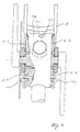
- FIG. 2 The shown in Fig. 2 and for the storage of a rear swing arm of a bicycle certain bearing unit is composed of two bearings according to FIG. 1 such that the curved radial regions 3.2 of the elastomer layers 3, based on the Contact level of the two bearings, essentially symmetrical, as for the outer surfaces of the elastomer layers 3 can be seen in FIG. 2.
- FIG. 3 illustrates a mounting unit according to FIG. 2 shown, which encloses a bottom bracket shaft 7 of a bicycle.
- a threaded bushing 8 is provided, by means of which the storage unit can be preloaded to the storage unit on the concrete Load ratios.
- the structure of the threaded bushing 8 is selected such that that in the state of a preloaded bearing unit - in Fig. 3 is a stress-free State shown - the free rotational mobility of the bottom bracket shaft 7 is guaranteed.
- the rear wheel swing arm 9 a bicycle, not shown here, connected by means of screws 10.
- the bearing bodies 1.1 and 1.2 have a recess 11 into which a bicycle frame 12 provided projection engages, so that the security against rotation of the bearing body 1.1 and 1.2 is given relative to the bicycle frame 12.
Abstract
Description
Es zeigen
- Fig. 1
- eine perspektivische Ansicht eines erfindungsgemäßen Lagers,
- Fig. 2
- eine stirnseitige Ansicht einer aus zwei Lagern gemäß Fig. 1 gebildeten Lagereinheit für die Hinterradschwinge eines Fahrrades,
- Fig. 3
- ein Lager gemäß Fig. 2 in Einbausituation und
- Fig. 4
- eine Darstellung gemäß Fig. 3 mit am Lager befestigter Hinterradschwinge eines Fahrrades.
Claims (9)
- Lager zur begrenzt drehbeweglichen Lagerung von Bauteilen, insbesondere der Hinterradschwinge eines Fahrrades im Fahrradrahmen, mit einem Lagerkörper, einem zum Lagerkörper beabstandeten, auslenkbaren Drehkörper und einem, mit dem Lagerkörper und dem Drehkörper verbundenen, eine begrenzte Drehbewegung ermöglichenden Zwischenelement,
dadurch gekennzeichnet, dass das Zwischenelement (3) eine axiale (3.1) und eine radiale Komponente (3.2) aufweist, die ineinander übergehen und eine Schicht bilden, derart, dass ein direkter Kontakt zwischen dem Lagerkörper (1, 1.1, 1.2) und dem Drehkörper (2, 2.1, 2.2) auch bei dynamischer Belastung des Lagers unterbleibt. - Lager nach Anspruch 1, dadurch gekennzeichnet, dass es sich bei dem radial erstreckten Zwischenelement um eine Elastomerschicht (3) handelt.
- Lager nach Anspruch 2, dadurch gekennzeichnet, dass die Dicke der Elastomerschicht (3) mit sich vergrößerndem Abstand vom Lagerzentrum zunimmt.
- Lager nach Anspruch 2 oder 3, dadurch gekennzeichnet, dass der Lagerkörper (1) und der Drehkörper (2) zueinander korrespondierend so ausgeführt sind, dass eine von einer ebenen Schicht abweichende wellenförmige Elastomerschicht (3) entsteht.
- Lager nach Anspruch 2 oder 4, dadurch gekennzeichnet, dass die Elastomerschicht (3) lagerzentrumsfern im Wesentlichen radial und lagerzentrumsnah im Wesentlichen axial verläuft.
- Lager nach Anspruch 2 oder 4, dadurch gekennzeichnet, dass ein weiterer Lagerkörper (1.1, 1.2) oder Drehkörper (2.1, 2.2) vorgesehen ist, so dass zwischen dem Lagerkörper (1) und den Drehkörpern (2.1, 2.2) bzw. zwischen dem Drehkörper(2) und den Lagerkörpern (1.1, 1.2) zwei Elastomerschichten (3) existieren. (1) und den Drehkörpern (2.1, 2.2) bzw. zwischen dem Drehkörper(2) und den Lagerkörpern (1.1, 1.2) zwei Elastomerschichten (3) existieren.
- Lager nach Anspruch 6, gekennzeichnet durch eine symmetrische Anordnung der Elastomerschichten (3) zueinander bezogen auf den als Lagerkörper oder Drehkörper ausgeführten Innenkörper (6) des Lagers.
- Lager nach Anspruch 2, dadurch gekennzeichnet, dass eine Einrichtung (8) zur Erzeugung einer Vorspannung in der Elastomerschicht (3) vorgesehen ist.
- Lager nach Anspruch 8, dadurch gekennzeichnet, dass es sich bei der Einrichtung zur Vorspannungserzeugung um eine Gewindebuchse (8) handelt, deren axiale Längenänderung der Einstellung des Grades der Vorspannung dient.
Applications Claiming Priority (2)
| Application Number | Priority Date | Filing Date | Title |
|---|---|---|---|
| DE10116603A DE10116603C1 (de) | 2001-04-03 | 2001-04-03 | Lager zur begrenzt drehbeweglichen Lagerung von Bauteilen |
| DE10116603 | 2001-04-03 |
Publications (3)
| Publication Number | Publication Date |
|---|---|
| EP1247731A2 true EP1247731A2 (de) | 2002-10-09 |
| EP1247731A3 EP1247731A3 (de) | 2003-09-17 |
| EP1247731B1 EP1247731B1 (de) | 2006-07-05 |
Family
ID=7680229
Family Applications (1)
| Application Number | Title | Priority Date | Filing Date |
|---|---|---|---|
| EP02006974A Expired - Lifetime EP1247731B1 (de) | 2001-04-03 | 2002-03-27 | Lager zur begrenzt drehbeweglichen Lagerung von Bauteilen |
Country Status (4)
| Country | Link |
|---|---|
| US (1) | US6637736B2 (de) |
| EP (1) | EP1247731B1 (de) |
| DE (2) | DE10116603C1 (de) |
| NO (1) | NO319361B1 (de) |
Cited By (2)
| Publication number | Priority date | Publication date | Assignee | Title |
|---|---|---|---|---|
| FR2861685A1 (fr) * | 2003-10-29 | 2005-05-06 | Berchet Groupe Soc | Cycle pourvu d'un bras oscillant par rapport au cadre |
| EP3025948A1 (de) * | 2014-11-28 | 2016-06-01 | Jörn GmbH | Fahrradrahmen mit einer hinterbaufederung |
Families Citing this family (5)
| Publication number | Priority date | Publication date | Assignee | Title |
|---|---|---|---|---|
| US7097169B2 (en) * | 2004-08-04 | 2006-08-29 | Skf Usa Inc. | Elastomeric bearing with modified cylindrical core |
| GB2431067B (en) * | 2005-10-07 | 2008-05-07 | Cramer Systems Ltd | Telecommunications service management |
| FR2973339B1 (fr) * | 2011-03-29 | 2014-08-22 | Snecma | Dispositif de suspension d'une turbomachine a un avion |
| US10214284B2 (en) * | 2013-09-30 | 2019-02-26 | Sikorsky Aircraft Corporation | Pitch bearing |
| US9340251B2 (en) * | 2014-07-16 | 2016-05-17 | Ford Global Technologies, Llc | Bicycle wheel axle |
Citations (2)
| Publication number | Priority date | Publication date | Assignee | Title |
|---|---|---|---|---|
| DE753841C (de) | 1936-11-04 | 1951-01-29 | Phaenomen Werke Gustav Hiller | Fahrrad mit um die Tretkurbelachse schwenkbarem Hinterrad |
| DE19745380A1 (de) | 1996-10-15 | 1998-04-16 | Walter Straubhaar | Fahrrad mit einer Federvorrichtung |
Family Cites Families (12)
| Publication number | Priority date | Publication date | Assignee | Title |
|---|---|---|---|---|
| US3124342A (en) * | 1964-03-10 | figure | ||
| US2158028A (en) * | 1937-07-12 | 1939-05-09 | James P Burke | Spring |
| US2203342A (en) * | 1937-09-30 | 1940-06-04 | Briggs Mfg Co | Spring device |
| US2231037A (en) * | 1939-11-30 | 1941-02-11 | Lester M Taylor | Vibration dampening device |
| US2873110A (en) * | 1954-10-25 | 1959-02-10 | Jonsson Einar | Torsion spring |
| DE2643166A1 (de) * | 1975-11-03 | 1977-05-12 | United Technologies Corp | Elastomeres lager fuer hubschrauberrotor |
| US4040690A (en) * | 1975-11-17 | 1977-08-09 | Lord Corporation | Laminated bearing |
| AU1650483A (en) * | 1982-07-05 | 1984-01-12 | Schull, J.L. | Cycle frame with torsion spring suspension |
| US4913411A (en) * | 1987-12-14 | 1990-04-03 | Ltv Energy Products Co. | High-capacity elastomeric combination journal-thrust bearing |
| DE8817269U1 (de) * | 1988-03-23 | 1996-08-22 | Clouth Gummiwerke Ag | Drehschwingungsdämpfer |
| DE4227226A1 (de) * | 1992-08-17 | 1994-02-24 | Erwin Keuschnigg | Federungseinrichtung für ein Zweirad |
| US6241224B1 (en) * | 1999-09-30 | 2001-06-05 | Xerox Corporation | Torsion spring |
-
2001
- 2001-04-03 DE DE10116603A patent/DE10116603C1/de not_active Expired - Fee Related
-
2002
- 2002-03-27 DE DE50207417T patent/DE50207417D1/de not_active Expired - Lifetime
- 2002-03-27 EP EP02006974A patent/EP1247731B1/de not_active Expired - Lifetime
- 2002-04-02 NO NO20021553A patent/NO319361B1/no unknown
- 2002-04-03 US US10/114,253 patent/US6637736B2/en not_active Expired - Fee Related
Patent Citations (2)
| Publication number | Priority date | Publication date | Assignee | Title |
|---|---|---|---|---|
| DE753841C (de) | 1936-11-04 | 1951-01-29 | Phaenomen Werke Gustav Hiller | Fahrrad mit um die Tretkurbelachse schwenkbarem Hinterrad |
| DE19745380A1 (de) | 1996-10-15 | 1998-04-16 | Walter Straubhaar | Fahrrad mit einer Federvorrichtung |
Cited By (2)
| Publication number | Priority date | Publication date | Assignee | Title |
|---|---|---|---|---|
| FR2861685A1 (fr) * | 2003-10-29 | 2005-05-06 | Berchet Groupe Soc | Cycle pourvu d'un bras oscillant par rapport au cadre |
| EP3025948A1 (de) * | 2014-11-28 | 2016-06-01 | Jörn GmbH | Fahrradrahmen mit einer hinterbaufederung |
Also Published As
| Publication number | Publication date |
|---|---|
| DE50207417D1 (de) | 2006-08-17 |
| NO20021553L (no) | 2002-10-04 |
| US20020140142A1 (en) | 2002-10-03 |
| US6637736B2 (en) | 2003-10-28 |
| EP1247731B1 (de) | 2006-07-05 |
| NO20021553D0 (no) | 2002-04-02 |
| EP1247731A3 (de) | 2003-09-17 |
| DE10116603C1 (de) | 2002-10-24 |
| NO319361B1 (no) | 2005-07-18 |
Similar Documents
| Publication | Publication Date | Title |
|---|---|---|
| DE19581613C2 (de) | Lager für ein Kraftfahrzeug und Verfahren zur Herstellung des Lagers | |
| EP1985475B1 (de) | Aufbauseitige Federbeinlagerung für Radaufhängungen | |
| DE4036050C1 (de) | ||
| DE3525213A1 (de) | Elastische buchse | |
| DE4138582C1 (de) | ||
| DE102009043552A1 (de) | Dämpfungsbuchse für Verbundlenkerhinterachse eines Kraftfahrzeuges | |
| DE10204975B4 (de) | Drehgelenk | |
| DE102012200001A1 (de) | Gummimetallager für Kraftfahrzeug-Radaufhängung, Trapezlenker und Radaufhängung | |
| DE102015109533B4 (de) | Gummi-Feststofflager zur Anordnung an einer Kraftfahrzeugachse | |
| DE10311679A1 (de) | Gelenkverbindung | |
| DE10116603C1 (de) | Lager zur begrenzt drehbeweglichen Lagerung von Bauteilen | |
| EP1565370B1 (de) | Schwenklager sowie mit einem solchen ausgestattete lenkachse | |
| DE102007027251A1 (de) | Oberes Verankerungssystem für ein Federbein eines Fahrzeuges | |
| DE19580267B4 (de) | Anordnung zur Aufhängung eines gefederten Fahrzeug-Fahrerhauses an einem Fahrzeugrahmen | |
| DE102014011191B4 (de) | Vorrichtung zum Verstellen von Sturz und/oder Spur eines Fahrzeugrads | |
| WO2009094973A1 (de) | Achsaufhängung für ein fahrzeug | |
| DE3529274A1 (de) | Schwingungstilger fuer rotierende wellen | |
| DE102005012751B4 (de) | Gelenklagerbuchse, insbesondere für einen Achslenker eines Kraftfahrzeugs | |
| EP0226702A1 (de) | Federelement | |
| EP0570626B1 (de) | Schwenklager | |
| EP1118791A2 (de) | Elastomer-Metall-Gelenkbuchse | |
| EP1535766B1 (de) | Radaufhängung für ein Kraftfahrzeug | |
| DE102012221841B4 (de) | Gummimetalllager für Kraftfahrzeug-Radaufhängung, Trapezlenker und Radaufhängung | |
| DE202006000820U1 (de) | Gelenklager, insbesondere zur Lagerung von Achslenkern in Kraftfahrzeugen | |
| WO2019192648A1 (de) | Gelenklager für ein radmodul eines kraftfahrzeugs |
Legal Events
| Date | Code | Title | Description |
|---|---|---|---|
| PUAI | Public reference made under article 153(3) epc to a published international application that has entered the european phase |
Free format text: ORIGINAL CODE: 0009012 |
|
| AK | Designated contracting states |
Kind code of ref document: A2 Designated state(s): AT BE CH CY DE DK ES FI FR GB GR IE IT LI LU MC NL PT SE TR |
|
| AX | Request for extension of the european patent |
Free format text: AL;LT;LV;MK;RO;SI |
|
| PUAL | Search report despatched |
Free format text: ORIGINAL CODE: 0009013 |
|
| AK | Designated contracting states |
Kind code of ref document: A3 Designated state(s): AT BE CH CY DE DK ES FI FR GB GR IE IT LI LU MC NL PT SE TR |
|
| AX | Request for extension of the european patent |
Extension state: AL LT LV MK RO SI |
|
| RIC1 | Information provided on ipc code assigned before grant |
Ipc: 7F 16F 1/54 B Ipc: 7B 62K 25/30 A Ipc: 7F 16F 15/126 B |
|
| 17P | Request for examination filed |
Effective date: 20040317 |
|
| AKX | Designation fees paid |
Designated state(s): DE FR IT NL |
|
| 17Q | First examination report despatched |
Effective date: 20050527 |
|
| GRAP | Despatch of communication of intention to grant a patent |
Free format text: ORIGINAL CODE: EPIDOSNIGR1 |
|
| GRAS | Grant fee paid |
Free format text: ORIGINAL CODE: EPIDOSNIGR3 |
|
| GRAA | (expected) grant |
Free format text: ORIGINAL CODE: 0009210 |
|
| AK | Designated contracting states |
Kind code of ref document: B1 Designated state(s): DE FR IT NL |
|
| PG25 | Lapsed in a contracting state [announced via postgrant information from national office to epo] |
Ref country code: IT Free format text: LAPSE BECAUSE OF FAILURE TO SUBMIT A TRANSLATION OF THE DESCRIPTION OR TO PAY THE FEE WITHIN THE PRESCRIBED TIME-LIMIT;WARNING: LAPSES OF ITALIAN PATENTS WITH EFFECTIVE DATE BEFORE 2007 MAY HAVE OCCURRED AT ANY TIME BEFORE 2007. THE CORRECT EFFECTIVE DATE MAY BE DIFFERENT FROM THE ONE RECORDED. Effective date: 20060705 Ref country code: NL Free format text: LAPSE BECAUSE OF FAILURE TO SUBMIT A TRANSLATION OF THE DESCRIPTION OR TO PAY THE FEE WITHIN THE PRESCRIBED TIME-LIMIT Effective date: 20060705 |
|
| REF | Corresponds to: |
Ref document number: 50207417 Country of ref document: DE Date of ref document: 20060817 Kind code of ref document: P |
|
| NLV1 | Nl: lapsed or annulled due to failure to fulfill the requirements of art. 29p and 29m of the patents act | ||
| EN | Fr: translation not filed | ||
| PLBE | No opposition filed within time limit |
Free format text: ORIGINAL CODE: 0009261 |
|
| STAA | Information on the status of an ep patent application or granted ep patent |
Free format text: STATUS: NO OPPOSITION FILED WITHIN TIME LIMIT |
|
| 26N | No opposition filed |
Effective date: 20070410 |
|
| PG25 | Lapsed in a contracting state [announced via postgrant information from national office to epo] |
Ref country code: FR Free format text: LAPSE BECAUSE OF FAILURE TO SUBMIT A TRANSLATION OF THE DESCRIPTION OR TO PAY THE FEE WITHIN THE PRESCRIBED TIME-LIMIT Effective date: 20070511 |
|
| PG25 | Lapsed in a contracting state [announced via postgrant information from national office to epo] |
Ref country code: FR Free format text: LAPSE BECAUSE OF FAILURE TO SUBMIT A TRANSLATION OF THE DESCRIPTION OR TO PAY THE FEE WITHIN THE PRESCRIBED TIME-LIMIT Effective date: 20060705 |
|
| PGFP | Annual fee paid to national office [announced via postgrant information from national office to epo] |
Ref country code: DE Payment date: 20140331 Year of fee payment: 13 |
|
| REG | Reference to a national code |
Ref country code: DE Ref legal event code: R231 Ref document number: 50207417 Country of ref document: DE |
|
| PG25 | Lapsed in a contracting state [announced via postgrant information from national office to epo] |
Ref country code: DE Free format text: LAPSE BECAUSE OF THE APPLICANT RENOUNCES Effective date: 20150331 |