EP1247577A2 - System zur Detektion von Fluiden in einem mikrofluidischen Bauteil - Google Patents
System zur Detektion von Fluiden in einem mikrofluidischen Bauteil Download PDFInfo
- Publication number
- EP1247577A2 EP1247577A2 EP02002154A EP02002154A EP1247577A2 EP 1247577 A2 EP1247577 A2 EP 1247577A2 EP 02002154 A EP02002154 A EP 02002154A EP 02002154 A EP02002154 A EP 02002154A EP 1247577 A2 EP1247577 A2 EP 1247577A2
- Authority
- EP
- European Patent Office
- Prior art keywords
- component
- light
- microchannel
- microfluidic
- light receiver
- Prior art date
- Legal status (The legal status is an assumption and is not a legal conclusion. Google has not performed a legal analysis and makes no representation as to the accuracy of the status listed.)
- Withdrawn
Links
- 239000012530 fluid Substances 0.000 title claims abstract description 11
- 239000007788 liquid Substances 0.000 claims description 29
- 238000001514 detection method Methods 0.000 claims description 9
- 238000000926 separation method Methods 0.000 claims description 7
- 230000001154 acute effect Effects 0.000 claims description 5
- 238000004458 analytical method Methods 0.000 claims description 3
- 238000005251 capillar electrophoresis Methods 0.000 claims description 3
- 238000000746 purification Methods 0.000 claims description 3
- 238000011156 evaluation Methods 0.000 claims description 2
- XLYOFNOQVPJJNP-UHFFFAOYSA-N water Substances O XLYOFNOQVPJJNP-UHFFFAOYSA-N 0.000 abstract 1
- 239000007789 gas Substances 0.000 description 13
- 229920003023 plastic Polymers 0.000 description 4
- 239000004033 plastic Substances 0.000 description 4
- 239000000758 substrate Substances 0.000 description 4
- 239000011521 glass Substances 0.000 description 3
- 238000005259 measurement Methods 0.000 description 3
- 230000005499 meniscus Effects 0.000 description 3
- 239000000919 ceramic Substances 0.000 description 2
- 230000000694 effects Effects 0.000 description 2
- 238000005516 engineering process Methods 0.000 description 2
- 229910052751 metal Inorganic materials 0.000 description 2
- 239000002184 metal Substances 0.000 description 2
- 150000002739 metals Chemical class 0.000 description 2
- 238000000034 method Methods 0.000 description 2
- 230000003287 optical effect Effects 0.000 description 2
- 239000004065 semiconductor Substances 0.000 description 2
- 102000004190 Enzymes Human genes 0.000 description 1
- 108090000790 Enzymes Proteins 0.000 description 1
- 230000002745 absorbent Effects 0.000 description 1
- 239000002250 absorbent Substances 0.000 description 1
- 230000004308 accommodation Effects 0.000 description 1
- 238000006243 chemical reaction Methods 0.000 description 1
- 230000000295 complement effect Effects 0.000 description 1
- 238000010276 construction Methods 0.000 description 1
- 238000006073 displacement reaction Methods 0.000 description 1
- 238000010828 elution Methods 0.000 description 1
- 238000005530 etching Methods 0.000 description 1
- 230000002349 favourable effect Effects 0.000 description 1
- 230000001771 impaired effect Effects 0.000 description 1
- 238000001459 lithography Methods 0.000 description 1
- 230000007257 malfunction Effects 0.000 description 1
- 238000004519 manufacturing process Methods 0.000 description 1
- 150000007523 nucleic acids Chemical class 0.000 description 1
- 102000039446 nucleic acids Human genes 0.000 description 1
- 108020004707 nucleic acids Proteins 0.000 description 1
- 230000005855 radiation Effects 0.000 description 1
- 239000007787 solid Substances 0.000 description 1
- 239000000126 substance Substances 0.000 description 1
- 230000001629 suppression Effects 0.000 description 1
- 230000007704 transition Effects 0.000 description 1
Images
Classifications
-
- G—PHYSICS
- G01—MEASURING; TESTING
- G01N—INVESTIGATING OR ANALYSING MATERIALS BY DETERMINING THEIR CHEMICAL OR PHYSICAL PROPERTIES
- G01N21/00—Investigating or analysing materials by the use of optical means, i.e. using sub-millimetre waves, infrared, visible or ultraviolet light
- G01N21/01—Arrangements or apparatus for facilitating the optical investigation
- G01N21/03—Cuvette constructions
- G01N21/0303—Optical path conditioning in cuvettes, e.g. windows; adapted optical elements or systems; path modifying or adjustment
-
- G—PHYSICS
- G01—MEASURING; TESTING
- G01N—INVESTIGATING OR ANALYSING MATERIALS BY DETERMINING THEIR CHEMICAL OR PHYSICAL PROPERTIES
- G01N21/00—Investigating or analysing materials by the use of optical means, i.e. using sub-millimetre waves, infrared, visible or ultraviolet light
- G01N21/17—Systems in which incident light is modified in accordance with the properties of the material investigated
- G01N21/41—Refractivity; Phase-affecting properties, e.g. optical path length
- G01N21/43—Refractivity; Phase-affecting properties, e.g. optical path length by measuring critical angle
-
- B—PERFORMING OPERATIONS; TRANSPORTING
- B01—PHYSICAL OR CHEMICAL PROCESSES OR APPARATUS IN GENERAL
- B01L—CHEMICAL OR PHYSICAL LABORATORY APPARATUS FOR GENERAL USE
- B01L2300/00—Additional constructional details
- B01L2300/06—Auxiliary integrated devices, integrated components
- B01L2300/0627—Sensor or part of a sensor is integrated
- B01L2300/0654—Lenses; Optical fibres
-
- B—PERFORMING OPERATIONS; TRANSPORTING
- B01—PHYSICAL OR CHEMICAL PROCESSES OR APPARATUS IN GENERAL
- B01L—CHEMICAL OR PHYSICAL LABORATORY APPARATUS FOR GENERAL USE
- B01L3/00—Containers or dishes for laboratory use, e.g. laboratory glassware; Droppers
- B01L3/50—Containers for the purpose of retaining a material to be analysed, e.g. test tubes
- B01L3/502—Containers for the purpose of retaining a material to be analysed, e.g. test tubes with fluid transport, e.g. in multi-compartment structures
- B01L3/5027—Containers for the purpose of retaining a material to be analysed, e.g. test tubes with fluid transport, e.g. in multi-compartment structures by integrated microfluidic structures, i.e. dimensions of channels and chambers are such that surface tension forces are important, e.g. lab-on-a-chip
- B01L3/502715—Containers for the purpose of retaining a material to be analysed, e.g. test tubes with fluid transport, e.g. in multi-compartment structures by integrated microfluidic structures, i.e. dimensions of channels and chambers are such that surface tension forces are important, e.g. lab-on-a-chip characterised by interfacing components, e.g. fluidic, electrical, optical or mechanical interfaces
Definitions
- the invention relates to a system for the detection of fluids in one microfluidic component.
- Microfluidic components in the sense of this application are components with at least a microchannel for storing and / or directing fluids, i.e. liquids and / or gases.
- the microchannels can also be referred to as capillary microchannels become.
- these microfluidic components can have other microstructures have, for example micropumps, microactuators, microsensors etc.
- Microfluidic components are characterized by characteristic transverse dimensions the microchannels (e.g. diameter or hydraulic diameter or width and height) of at most about 1500 ⁇ m (preferably at most about 500 ⁇ m) and a minimum of about 5 ⁇ m (preferably a minimum of about 10 ⁇ m).
- the microchannels can also be called capillary microchannels.
- microstructures can also be found in the aforementioned Areas.
- they can be made from semiconductors and / or plastics and / or glass and / or ceramics and / or metals be, whereby suitable manufacturing processes of microtechnology or Microstructuring can be used, e.g. Lithography and etching processes (for semiconductors) or Liga processes (for metals, plastics and ceramics).
- the state of filling with a fluid or Drainage is not readily controllable, although in many cases would be desirable. For example, it would be helpful to check the filling or emptying status of a microdosing system in order to avoid incorrect dosing.
- gas bubbles can form which can lead to malfunctions of the microfluidic component.
- microdosing systems are described, one of which Include free jet dosing or a micro diaphragm pump.
- One of these microdosing systems has a reservoir, a micromembrane pump, the input of which with the Reservoir is connected, one connected to the outlet of the micromembrane pump Dosing opening and one that is operatively connected to the micromembrane pump Dosing control, with micro diaphragm pump and reservoir in microsystem technology or hybrid technology to one interchangeable with an actuation module connected component are summarized.
- the dosing control controls this Dosing volume over the stroke volume of the micromembrane pump.
- the Dosing control for setting a starting position for shifting the Liquid column with a sensor for detecting the meniscus of the liquid on Start of a displacement distance of the liquid connected.
- the sensor is one Dispensing tubes assigned to the liquid.
- the Dosing amount controlled via the known stroke volume of the micromembrane pump. at further doses, the dosing control can assume that the liquid column is at the end of the dispensing tube. With this microdosing system Willingness to dose is only determined at the start of operation. Since the Dosing amount is controlled via the known stroke volume, it can lead to incorrect dosing come when the micro diaphragm pump promotes air pockets or the reservoir is exhausted.
- the optical measurement is particularly due to scattering and refraction effects and impaired the low signal swing.
- the measurement is based on a detection of the Interface limited and can not distinguish whether liquid or There is air at the sensor.
- the object of the invention is a system for detection creating fluids in a microfluidic device that is a cheaper Provides measurement signal and a distinction between liquids and gases allows.
- the invention takes advantage of the fact that on the border from an optically denser to one optically thinner medium depending on the refractive indices of the two media Limit angle exists, so that in the denser medium on the limit to thinner medium incident light beam whose angle of incidence is the critical angle is exceeded, is completely reflected at this limit (total reflection). Further it takes advantage of the fact that the critical angle when transitioning from a transparent one Solid (e.g. made of plastic or glass) to air or another gas is smaller than the critical angle at the transition to a liquid. Light transmitter and Light receivers are therefore on the surfaces inclined at an acute angle to each other the transparent area of the boundary wall, i.e.
- the optically denser Area aligned that total gas reflection on both surfaces when a gas is present takes place and the light beam reaches the light receiver completely.
- the inclination of the surfaces to each other ensures that the reflected Beam of light from one surface to the other.
- the light beam enters the microchannel on at least one of the surfaces, so that the light receiver measures a significantly reduced or no light signal.
- microchannel or capillary microchannel has very small transverse dimensions has an even meniscus between the liquid and Gas and there are no droplets or air bubbles on the inclined surfaces, which can falsify the result.
- the boundary wall can especially in the transparent area where the two are at an acute angle to each other inclined surfaces are available, made of plastic or glass.
- a carryover of liquid by light transmitter and light receiver is excluded, since these are separated from the microchannel by the boundary wall.
- the construction is simple because the light transmitter and light receiver are side by side are directed from one side to the inclined surfaces.
- the System has a clear signal swing and high reliability.
- the microchannel can also be in the area delimited by the inclined surfaces be made correspondingly thin as in adjacent areas, so that the Fluids can be introduced to the measuring range under favorable conditions.
- it points in the area of the inclined surfaces and the adjacent areas have a substantially constant cross section.
- the angle between the two is Areas about 80 to 100 °, preferably about 90 °.
- the light transmitter and the light receiver can then with their light axes approximately parallel and at an angle of incidence aligned from about 45 ° to the respectively assigned inclined surfaces his.
- the component has a plurality of layers one on top of the other Walls on. These can be carried out essentially on both sides be, with a boundary wall of the microchannel the inclined surfaces on a (e.g. prismatic) projection and the opposite boundary wall of the microchannel can have a receptacle receiving the projection.
- the Microchannel can only be formed in the wall receiving the projection and be covered by the wall having the projection or Have sections in both walls that complement each other to form the microchannel.
- the light transmitter and light receiver are executed in a single component, which is advantageous for accommodation, Assembly and alignment is.
- the light transmitter and light receiver are from microfluidic component separated, making the interchangeability of the microfluidic Favored component and in particular its execution as disposable becomes.
- Light transmitters and light receivers can be used especially in the visible range Light work. According to one embodiment, they work in the IR area. The transparent one The area of the component is then transparent to IR radiation.
- the system is integrated in a device with which the component is detachably connected.
- the microfluidic component is preferred a disposable, i.e. a component that is not reused after use, but instead is thrown away.
- the device can in particular a receptacle for inserting the Have component. Furthermore, it can be a releasable clamp connection and / or locking and / or have a magnetic connection to the component.
- the device has on the side of the microfluidic component, which is opposite the side with the light transmitter and the Light receiver is arranged, a wall with specific reflection properties, a specific one in the absence of a microfluidic component Incidence of light from the light emitter in the light receiver has the consequence of the incidence of light in the presence of a microfluidic Component differs. This enables gas or liquid to be detected in a component, a detection of whether the component is actually present in the device is.
- the device is a handheld device.
- the microfluidic component can in particular be a cartridge a microdosing system, for example a cartridge of an enzyme dosing device, as described in WO 99/10099.
- the microfluidic component is one Dosing component, analysis chip, PCR component, purification component, liquid transport component, Capillary electrophoresis component or a separation column component.
- a dosing component is generally used to measure and make available as exact as possible one or more amounts of liquid (or liquid aliquots).
- An analysis chip is a component with a reaction chamber (s), detection structures, Entry and / or exit ports and fluidic connections. Here's that too Detect the fill level with liquid of interest.
- a PCR component is used for recording, targeted temperature control and forwarding a sample containing nucleic acid with the aim of amplifying the DNA.
- a purification component is used for the selective separation of specific molecules from a sample, e.g. by binding to surfaces, mechanical filters or chemical separation (elution).
- a liquid transport component serves the active (e.g. via pressure difference) or passive (e.g. via capillary effect) transport of a liquid.
- a capillary electrophoresis component is used for the spatial separation of molecules according to their size (chain length), whereby the movement of the molecules through a electrical potential difference is caused.
- a separation column component is used for the spatial separation of molecules according to binding properties, the movement of the molecules by pressure difference or Capillarity can take place.
- an embodiment of the invention provides that one with the light receiver connected evaluation device when detecting gas and / or Liquid an output and / or a switching on or off of the device and / or triggers a device function.
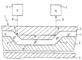
- the microfluidic component 1 has a base body 2, on which a cover 3 is layered. Between base body 2 and cover 3 is a microchannel 4 or Capillary microchannel formed so that base body 2 and cover 3 boundary walls form for the microchannel 4.
- the microchannel 4 runs in two lateral sections 4 ′, 4 ′′ essentially parallel to the outer surfaces of the base body 2 and the cover 3. In an area in between, it has two sections 4 ′′, 4 IV inclined at an acute angle to one another, between which in turn one Section 4 V is arranged, which is substantially parallel to the outer surfaces.
- the sections 4 ′′ and 4 IV of the microchannel 4 are aligned at approximately an angle of 45 ° to the outer surfaces of the base body 2 and cover 3.
- the cross section of the microchannel 4 is essentially constant.
- the inclined sections 4 ′′, 4 IV of the microchannel 4 are delimited by the cover 3 from two surfaces 3 ′, 3 ′′ inclined to the cover plane approximately at an angle of 45 ° and to one another approximately at an angle of 90 °.
- the basic body 2 has parallel surfaces 2 ', 2 "to these surfaces 3', 3". Between the surfaces 3 ', 3 ", the cover has a surface 3"' parallel to the cover plane, to which the base body 2 has a parallel surface 2 "'.
- the base body 2 is essentially planar, being in its Top of the microchannel 4 and a recess with the surfaces 2 ', 2 ", 2' '' incorporated is.
- the lid 3 is also essentially flat, but has the surfaces 3 ', 3 ", 3 "'on a prism-shaped elevation. The elevation engages in the recess and the adjacent plan areas of cover 3 cover the adjacent ones Sections 4 ', 4 "of the channel.
- the cover 3 is made transparent in the region which adjoins the sections 4 "', 4 IV and 4 V of the microchannel 4. In the sections which adjoin the lateral sections 4', 4" of the microchannel 4, it can also be made opaque.
- the base body 2 is at least in its areas below the transparent one Area of the lid 3, i.e. in the areas 2 ', 2 "and the area in between Area 2 "', absorbent.
- the component 1 comprising the base body 2 and the cover 3 is on a partially reflecting component Substrate 5 arranged.
- a light transmitter 6 and a light receiver 7 arranged with parallel light axes 8, 9.
- the light axis 8 of the light transmitter 6 is on the inclined surface 3 'and the light axis 9 of the light receiver 7 is on the inclined surface 3 "aligned, each at an angle of incidence of 45 °.
- This system can detect the presence or absence of liquid below of the surfaces 3 ', 3 ". Is located in the microchannel 4 on the surfaces 3', 3" Air, so the light beam is reflected by the light transmitter 6 in the light receiver 7 directed, as shown in the figure.
- the component 1 is not present above the substrate 5, the one from the light transmitter 6 emitted light beam partially reflected in the light receiver 7, being ascertainable by evaluating the signal supplied by the light receiver 7 is that the reflection has occurred on the substrate. The absence of the component 1 above the substrate 5 can thus be detected.
Landscapes
- Physics & Mathematics (AREA)
- Health & Medical Sciences (AREA)
- Life Sciences & Earth Sciences (AREA)
- Chemical & Material Sciences (AREA)
- Analytical Chemistry (AREA)
- Biochemistry (AREA)
- General Health & Medical Sciences (AREA)
- General Physics & Mathematics (AREA)
- Immunology (AREA)
- Pathology (AREA)
- Optical Measuring Cells (AREA)
- Investigating Or Analysing Materials By Optical Means (AREA)
- Measuring Or Testing Involving Enzymes Or Micro-Organisms (AREA)
Abstract
Description
- das mikrofluidische Bauteil weist mindestens einen Mikrokanal mit einer Begrenzungswand auf, die in einem transparenten Bereich dem Mikrokanal zugewandt zwei spitzwinklig zueinander geneigte Flächen hat,
- ein Lichtsender und ein Lichtempfänger, die außerhalb des Bauteils angeordnet sind, sind so auf die geneigten Flächen in den transparenten Bereich der Begrenzungswand gerichtet, daß ein vom Lichtsender ausgesandter Lichtstrahl beim Anliegen eines Gases im Mikrokanal an den beiden Flächen nach Totalreflexion an den beiden Flächen auf den Lichtempfänger trifft und beim Anliegen von Flüssigkeit an mindestens einer der beiden Flächen in den Mikrokanal eintritt und hierdurch der Lichteinfall in den Lichtempfänger reduziert oder unterbunden wird.
Claims (18)
- System zur Detektion von Fluiden in einem mikrofluidischen Bauteil (1) mit folgenden Merkmalen:das mikrofluidische Bauteil (1) weist mindestens einen Mikrokanal (4) mit einer Begrenzungswand (3) auf, die in einem transparenten Bereich dem Mikrokanal (4) zugewandt zwei spitzwinklig zueinander geneigte Flächen (3', 3'') hat,ein Lichtsender (6) und ein Lichtempfänger (7), die außerhalb des Bauteils (1) angeordnet sind, sind so auf die geneigten Flächen (3', 3") in dem transparenten Bereich der Begrenzungswand (3) gerichtet, daß ein vom Lichtsender (6) ausgesandter Lichtstrahl bei Anliegen eines Gases im Mikrokanal (4) an den beiden Flächen (3', 3") nach Totalreflexion an den beiden Flächen (3', 3") auf den Lichtempfänger (7) trifft und beim Anliegen von Flüssigkeit im Mikrokanal (4) an mindestens einer der beiden Flächen (3' 3") in den Mikrokanal (4) eintritt und hierdurch der Lichteinfall in den Lichtempfänger (7) reduziert oder unterbunden wird.
- System nach Anspruch 1, bei dem der Mikrokanal (4) zumindest im Bereich der geneigten Flächen (3', 3") und in angrenzenden Bereichen einen im wesentlichen konstanten Querschnitt hat.
- System nach Anspruch 1 oder 2, bei dem die der Begrenzungswand (3) mit den geneigten Flächen (3', 3") gegenüberliegende Begrenzungswand (2) zumindest in den Bereichen gegenüber geneigten Flächen (3', 3") und in den angrenzenden Bereichen im wesentlichen parallele obere und untere Begrenzungswände (2', 2") hat.
- System nach einem der Ansprüche 1 bis 3, bei dem die der Begrenzungswand mit den geneigten Flächen (3', 3") gegenüberliegende Begrenzungswand (2) zumindest in den den geneigten Flächen gegenüberliegenden Bereichen lichtabsorbierend ist.
- System nach einem der Ansprüche 1 bis 4, bei dem der Winkel zwischen den beiden Flächen (3', 3") etwa 80 bis 90° beträgt.
- System nach einem der Ansprüche 1 bis 5, bei dem das Bauteil (1) mehrere übereinandergeschichtete Wände (2, 3) aufweist.
- System nach einem der Ansprüche 1 bis 6, bei dem Lichtsender (6) und Lichtempfänger (7) in einem einzigen Bauteil ausgeführt sind.
- System nach einem der Ansprüche 1 bis 7, bei dem Lichtsender (6) und Lichtempfänger (7) von dem mikrofluidischen Bauteil (1) getrennt sind.
- System nach einem der Ansprüche 1 bis 8, bei dem Lichtsender (6) und Lichtempfänger (7) im IR-Bereich arbeiten.
- System nach einem der Ansprüche 1 bis 9, das in ein Gerät integriert ist, mit dem das mikrofluidische Bauteil (1) lösbar verbunden ist.
- System nach einem der Ansprüche 1 bis 10, bei dem das mikrofluidische Bauteil (1) ein Disposable ist.
- System nach Anspruch 10 oder 11, bei dem das mikrofluidische Bauteil (1) in eine Aufnahme des Gerätes eingesetzt ist.
- System nach einem der Ansprüche 10 bis 12, bei dem das Gerät eine lösbare Klemmverbindung und/oder Verriegelung und/oder magnetische Verbindung mit dem mikrofluidischen Bauteil (1) hat.
- System nach einem der Ansprüche 10 bis 13, bei dem das Gerät auf der Seite des mikrofluidischen Bauteils (1), die gegenüber der Seite mit dem Lichtsender (6) und Lichtempfänger (7) angeordnet ist, eine Wand (5) mit spezifischen Reflexionseigenschaften hat, die bei Nichtvorhandensein eines mikrofluidischen Bauteils (1) einen spezifischen Lichteinfall des vom Lichtsender (6) stammenden Lichts in den Lichtempfänger (7) zur Folge hat, der sich vom Lichteinfall bei Vorhandenseins eines mikrofluidischen Bauteils (1) im Gerät unterscheidet.
- System nach einem der Ansprüche 10 bis 14, bei dem das Gerät ein Handgerät ist.
- System nach einem der Ansprüche 1 bis 15, bei dem das mikrofluidische Bauteil (1) eine Kartusche eines Mikrodosiersystems ist.
- System nach einem der Ansprüche 1 bis 16, bei dem das mikrofluidische Bauteil (1) ein Dosierbauteil, Analysenchip, PCR-Bauteil, Aufreinigungsbauteil, Flüssigkeitstransportbauteil, Kapillarelektrophoresebauteil oder Trennsäulenbauteil ist.
- System nach einem der Ansprüche 1 bis 17, bei dem eine Auswerteeinrichtung ein Detektieren von Gas und/oder Flüssigkeit einer Ausgabe und/oder ein Einoder Ausschalten eines Gerätes und/oder eine Gerätefunktion auslöst.
Applications Claiming Priority (2)
| Application Number | Priority Date | Filing Date | Title |
|---|---|---|---|
| DE10116674A DE10116674C2 (de) | 2001-04-04 | 2001-04-04 | Vorrichtung zur Detektion von Fluiden in einem mikrofluidischen Bauteil |
| DE10116674 | 2001-04-04 |
Publications (2)
| Publication Number | Publication Date |
|---|---|
| EP1247577A2 true EP1247577A2 (de) | 2002-10-09 |
| EP1247577A3 EP1247577A3 (de) | 2004-02-25 |
Family
ID=7680283
Family Applications (1)
| Application Number | Title | Priority Date | Filing Date |
|---|---|---|---|
| EP02002154A Withdrawn EP1247577A3 (de) | 2001-04-04 | 2002-01-29 | System zur Detektion von Fluiden in einem mikrofluidischen Bauteil |
Country Status (3)
| Country | Link |
|---|---|
| US (1) | US6774616B2 (de) |
| EP (1) | EP1247577A3 (de) |
| DE (1) | DE10116674C2 (de) |
Cited By (3)
| Publication number | Priority date | Publication date | Assignee | Title |
|---|---|---|---|---|
| DE102005062174B3 (de) * | 2005-12-23 | 2007-05-31 | INSTITUT FüR MIKROTECHNIK MAINZ GMBH | Meßchip |
| WO2008145382A3 (de) * | 2007-06-01 | 2009-01-22 | Hahn Schickard Ges | Vorrichtung und verfahren zum ermöglichen der bewertung eines füllzustands |
| EP1712282A3 (de) * | 2005-04-15 | 2010-01-27 | Hitachi Software Engineering Co., Ltd. | Testchip und System eines Testchips |
Families Citing this family (12)
| Publication number | Priority date | Publication date | Assignee | Title |
|---|---|---|---|---|
| WO2005043134A1 (en) * | 2003-10-30 | 2005-05-12 | Bayer Healthcare Llc | Optical cuvette with platform-and-well construction |
| EP1541991A1 (de) * | 2003-12-12 | 2005-06-15 | STMicroelectronics S.r.l. | Integrierter chemischer Reaktor aus Halbleitermaterial zur Echtzeit-Überwachung von biologischen Reaktionen |
| SE0402731D0 (sv) * | 2004-11-10 | 2004-11-10 | Gyros Ab | Liquid detection and confidence determination |
| US20060252087A1 (en) * | 2005-01-18 | 2006-11-09 | Biocept, Inc. | Recovery of rare cells using a microchannel apparatus with patterned posts |
| CN103382434B (zh) | 2005-01-18 | 2016-05-25 | 生物概念股份有限公司 | 利用含排列成图案的立柱的微通道分离细胞 |
| US20090136982A1 (en) | 2005-01-18 | 2009-05-28 | Biocept, Inc. | Cell separation using microchannel having patterned posts |
| EP3626345A1 (de) | 2007-04-04 | 2020-03-25 | ANDE Corporation | Systeme zur schnellen multiplex-amplifikation von zielnukleinsäuren |
| DE102009000529A1 (de) | 2009-01-30 | 2010-08-19 | INSTITUT FüR MIKROTECHNIK MAINZ GMBH | Mikrofluidischer Chip mit Druckmesseinrichtung |
| US9550985B2 (en) | 2009-06-15 | 2017-01-24 | Netbio, Inc. | Methods for forensic DNA quantitation |
| US10076751B2 (en) | 2013-12-30 | 2018-09-18 | General Electric Company | Systems and methods for reagent storage |
| US9399216B2 (en) | 2013-12-30 | 2016-07-26 | General Electric Company | Fluid transport in microfluidic applications with sensors for detecting fluid presence and pressure |
| EP3978125A1 (de) * | 2020-09-30 | 2022-04-06 | iCare Diagnostics International Co. Ltd. | Nukleinsäuredetektionskit und nukleinsäuredetektionsvorrichtung |
Citations (1)
| Publication number | Priority date | Publication date | Assignee | Title |
|---|---|---|---|---|
| DE4305924A1 (de) * | 1993-02-26 | 1994-09-01 | Hahn Schickard Ges | Vorrichtung zur Detektion der Überfüllung eines Überlaufkanals für Flüssigkeiten |
Family Cites Families (8)
| Publication number | Priority date | Publication date | Assignee | Title |
|---|---|---|---|---|
| DE3243839A1 (de) * | 1982-11-26 | 1984-05-30 | Kromberg & Schubert, 5600 Wuppertal | Vorrichtung zur hoehenstandsmessung von fluessigkeiten in behaeltern, insbesondere fuellstandsanzeige fuer kraftfahrzeuge |
| US5072595A (en) * | 1990-09-19 | 1991-12-17 | Barbier William J | Apparatus for detecting small bubbles in a pressurized fluid stream |
| US5139661A (en) * | 1991-01-11 | 1992-08-18 | Biotage Inc. | Critical angle refractive index detector |
| US5548393A (en) * | 1993-07-05 | 1996-08-20 | Nippondenso Co., Ltd. | Oil deterioration detection apparatus and apparatus for detecting particles in liquid |
| DE19527666C1 (de) * | 1995-07-28 | 1997-04-03 | Aeg Sensorsysteme Gmbh | Automatisches Entlüftungsventil für Hydraulikanlagen |
| US6097479A (en) * | 1996-10-01 | 2000-08-01 | Texas Instruments Incorporated | Critical angle sensor |
| DE19737173B4 (de) * | 1997-08-26 | 2007-04-05 | Eppendorf Ag | Mikrodosiersystem |
| US6540895B1 (en) * | 1997-09-23 | 2003-04-01 | California Institute Of Technology | Microfabricated cell sorter for chemical and biological materials |
-
2001
- 2001-04-04 DE DE10116674A patent/DE10116674C2/de not_active Expired - Fee Related
-
2002
- 2002-01-29 EP EP02002154A patent/EP1247577A3/de not_active Withdrawn
- 2002-03-01 US US10/086,774 patent/US6774616B2/en not_active Expired - Fee Related
Patent Citations (1)
| Publication number | Priority date | Publication date | Assignee | Title |
|---|---|---|---|---|
| DE4305924A1 (de) * | 1993-02-26 | 1994-09-01 | Hahn Schickard Ges | Vorrichtung zur Detektion der Überfüllung eines Überlaufkanals für Flüssigkeiten |
Cited By (5)
| Publication number | Priority date | Publication date | Assignee | Title |
|---|---|---|---|---|
| EP1712282A3 (de) * | 2005-04-15 | 2010-01-27 | Hitachi Software Engineering Co., Ltd. | Testchip und System eines Testchips |
| DE102005062174B3 (de) * | 2005-12-23 | 2007-05-31 | INSTITUT FüR MIKROTECHNIK MAINZ GMBH | Meßchip |
| DE102005062174C5 (de) * | 2005-12-23 | 2010-05-06 | INSTITUT FüR MIKROTECHNIK MAINZ GMBH | Meßchip |
| US7894071B2 (en) | 2005-12-23 | 2011-02-22 | Institut Fuer Mikrotechnik Mainz Gmbh | Measurement chip |
| WO2008145382A3 (de) * | 2007-06-01 | 2009-01-22 | Hahn Schickard Ges | Vorrichtung und verfahren zum ermöglichen der bewertung eines füllzustands |
Also Published As
| Publication number | Publication date |
|---|---|
| US20020145121A1 (en) | 2002-10-10 |
| US6774616B2 (en) | 2004-08-10 |
| DE10116674C2 (de) | 2003-08-14 |
| DE10116674A1 (de) | 2002-10-17 |
| EP1247577A3 (de) | 2004-02-25 |
Similar Documents
| Publication | Publication Date | Title |
|---|---|---|
| DE19648695C2 (de) | Vorrichtung zur automatischen und kontinuierlichen Analyse von Flüssigkeitsproben | |
| DE10116674C2 (de) | Vorrichtung zur Detektion von Fluiden in einem mikrofluidischen Bauteil | |
| DE69128700T2 (de) | Vorrichtung zur quantitativen Entnahme von Flüssigkeitsproben | |
| EP1256543B1 (de) | Mikrofluidisches Speicher- und/oder Dosierbauteil | |
| DE19947495C2 (de) | Mikrofluidischer Mikrochip | |
| DE19802368C1 (de) | Mikrodosiervorrichtung | |
| DE69727422T2 (de) | Vorrichtung zur Handhabung von Mikroflüssigkeitsmengen | |
| EP0988526B1 (de) | Anordnung zur detektion biochemischer oder chemischer substanzen mittels fluoreszenzlichtanregung und verfahren zu deren herstellung | |
| EP0725267B1 (de) | Elektrisch steuerbare Mikro-Pipette | |
| US10391487B2 (en) | Biologic fluid analysis cartridge with sample handling portion and analysis chamber portion | |
| WO1998022803A1 (de) | Mikromechanische transmissionsmesszelle | |
| DE102009015395A1 (de) | Vorrichtung zur Behandlung und/oder Untersuchung eines Fluids, insbesondere Flusszelle | |
| EP2988871B1 (de) | Verfahren zur befüllung einer mikrofluidischen vorrichtung mittels eines dispensiersystems, und entsprechendes testsystem | |
| DE69823904T2 (de) | Mikromechanische Pipettiervorrichtung | |
| CN101187669A (zh) | 微芯片检查系统以及在微芯片检查系统中使用的方法 | |
| WO2010086328A1 (de) | Mikrofluidischer chip mit druckmesseinrichtung | |
| DE102008002509A1 (de) | Stopped-Flow-Chip | |
| DE102008042071A1 (de) | Mikrodosierpumpe | |
| DE10135963B4 (de) | Vorrichtung zum Pipettieren einer Flüssigkeit | |
| DE19647644C2 (de) | Mikromechanische Transmissionsmeßzelle | |
| DE10321472B4 (de) | Fluidik-Modul, Verfahren zu seiner Herstellung und Verfahren zum Betreiben eines Fluidik-Moduls | |
| US20100296972A1 (en) | Flow cell | |
| EP2686664B1 (de) | Flache optische mediendetektion in mindestens zwei schichten mit optischer trennung | |
| DE112018007919T5 (de) | Feinstaub-sensor | |
| US20130167945A1 (en) | Biologic fluid analysis cartridge with volumetric sample metering |
Legal Events
| Date | Code | Title | Description |
|---|---|---|---|
| PUAI | Public reference made under article 153(3) epc to a published international application that has entered the european phase |
Free format text: ORIGINAL CODE: 0009012 |
|
| AK | Designated contracting states |
Kind code of ref document: A2 Designated state(s): AT BE CH CY DE DK ES FI FR GB GR IE IT LI LU MC NL PT SE TR |
|
| AX | Request for extension of the european patent |
Free format text: AL;LT;LV;MK;RO;SI |
|
| PUAL | Search report despatched |
Free format text: ORIGINAL CODE: 0009013 |
|
| AK | Designated contracting states |
Kind code of ref document: A3 Designated state(s): AT BE CH CY DE DK ES FI FR GB GR IE IT LI LU MC NL PT SE TR |
|
| AX | Request for extension of the european patent |
Extension state: AL LT LV MK RO SI |
|
| RIC1 | Information provided on ipc code assigned before grant |
Ipc: 7G 01N 21/43 A |
|
| 17P | Request for examination filed |
Effective date: 20040318 |
|
| AKX | Designation fees paid |
Designated state(s): AT BE CH CY DE DK ES FI FR GB GR IE IT LI LU MC NL PT SE TR |
|
| 17Q | First examination report despatched |
Effective date: 20061011 |
|
| STAA | Information on the status of an ep patent application or granted ep patent |
Free format text: STATUS: THE APPLICATION IS DEEMED TO BE WITHDRAWN |
|
| 18D | Application deemed to be withdrawn |
Effective date: 20160802 |