EP1247445A2 - Vorrichtung zum Melken von Tieren - Google Patents
Vorrichtung zum Melken von Tieren Download PDFInfo
- Publication number
- EP1247445A2 EP1247445A2 EP02077630A EP02077630A EP1247445A2 EP 1247445 A2 EP1247445 A2 EP 1247445A2 EP 02077630 A EP02077630 A EP 02077630A EP 02077630 A EP02077630 A EP 02077630A EP 1247445 A2 EP1247445 A2 EP 1247445A2
- Authority
- EP
- European Patent Office
- Prior art keywords
- milking
- implement
- construction
- robot
- treatment
- Prior art date
- Legal status (The legal status is an assumption and is not a legal conclusion. Google has not performed a legal analysis and makes no representation as to the accuracy of the status listed.)
- Withdrawn
Links
Images


Classifications
-
- A—HUMAN NECESSITIES
- A01—AGRICULTURE; FORESTRY; ANIMAL HUSBANDRY; HUNTING; TRAPPING; FISHING
- A01J—MANUFACTURE OF DAIRY PRODUCTS
- A01J5/00—Milking machines or devices
- A01J5/007—Monitoring milking processes; Control or regulation of milking machines
- A01J5/0075—Monitoring milking processes; Control or regulation of milking machines with a specially adapted stimulation of the teats
-
- A—HUMAN NECESSITIES
- A01—AGRICULTURE; FORESTRY; ANIMAL HUSBANDRY; HUNTING; TRAPPING; FISHING
- A01J—MANUFACTURE OF DAIRY PRODUCTS
- A01J5/00—Milking machines or devices
- A01J5/017—Automatic attaching or detaching of clusters
- A01J5/0175—Attaching of clusters
-
- A—HUMAN NECESSITIES
- A01—AGRICULTURE; FORESTRY; ANIMAL HUSBANDRY; HUNTING; TRAPPING; FISHING
- A01J—MANUFACTURE OF DAIRY PRODUCTS
- A01J7/00—Accessories for milking machines or devices
- A01J7/04—Accessories for milking machines or devices for treatment of udders or teats, e.g. for cleaning
Definitions
- the invention relates to an implement for milking animals as described in the preamble of claim 1.
- Implements are known in which the milking members are also used for pre-treatment of the teats of an animal to be milked. This has inter alia the disadvantage that the milking members are contaminated, so that they have to be cleaned before milking, which is a time consuming and laborious process. Furthermore implements are known in which pre-treatment members are positioned with the aid of separate robot arms. Such implements are laborious and expensive. Finally implements are known in which one single robot arm is used to position milking members and a pre-treatment member.
- the invention aims at obviating the above-mentioned drawbacks and to provide an implement which on the one hand can be controlled in a simple and accurate manner and on the other hand is adapted to operate quickly and efficiently. According to the invention this is achieved by means of the measures mentioned in the characterizing part of claim 1.
- Such ball bearings enable the hingeable construction to carry out the movements imposed by the control mechanism of the milking robot more quickly. Moreover such bearings only need to be greased once.
- all hinge points of the hingeable construction are provided with ball bearings, so that the entire robot arm can move more quickly.
- at least one hinge point of the hingeable construction is provided with a clinometer for determining the orientation of the robot arm.
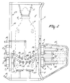
- FIGS 1, 2 and 3 are a side view, a plan view and a rear view respectively of the implement for automatically milking animals according to the invention.
- the implement comprises a milk stand in a milkbox 1 which is provided in longitudinal direction at one lateral side with an entrance door 2 via which an animal 3 to be milked can enter the milkbox 1, and an exit door 4 via which the animal 3 can leave the milkbox 1.
- a feed trough 5 in which fodder, such as e.g. concentrate, can be fed to the animal 3 by means of a (non-shown) fodder metering system.
- the entrance door 2 and the exit door 4 can be operated automatically by means of a non-shown computer.
- the animal 3 is provided with a collar 6 with a transponder which is adapted to cooperate with a (non-shown) animal identification system, so that the animal 3 in the milkbox 1 can be automatically identified.
- a transponder which is adapted to cooperate with a (non-shown) animal identification system, so that the animal 3 in the milkbox 1 can be automatically identified.
- the milkbox 1 further comprises a milking robot 7 having a number of (e.g. four) robot arms 8 for positioning means for treating the teats of the animal 3 to be milked.
- the robot arms 8 are each fastened to upper beams 12 of a frame 13 of the milkbox 1 by means of three hingeable constructions, such as e.g. parallelogram constructions 9, 10 and 11.
- the parallelogram constructions 9, 10 and 11 can be automatically controlled by means of non-shown control means and enable each of the robot arms 8 to carry out movements in three dimensions.
- the control means may comprise servo-pneumatic and/or servo-hydraulic cylinders (see Figures 1 - 3) and/or stepper motors.
- each robot arm 8 is each provided with one milking member 14 and a separate pre-treatment member 15.
- Each milking member 14 is adapted to milk one of the teats of the animal 3 to be milked and comprises for that purpose a teat cup (known per se) for collecting and conveying the milk yielded, the inside of said teat cup being provided with pulsation means, as will be explained in further detail with reference to Figure 7.
- Each pre-treatment member 15 is adapted to clean and/or to stimulate and/or to foremilk one of the teats of the animal 3 to be milked, as will be explained in further detail, also with reference to Figure 7.
- Protective brackets 16 ensure the protection of the parallelogram constructions 9, 10, 11 with the robot arms 8.
- the robot arms 8 are also provided with non-shown detectors for an accurate determination of the position of the teats of the animal 3 to be milked in relation to the relevant robot arms 8.
- the milkbox 1 is further provided with sensors 17 for determining the position of the animal 3 in relation to the milkbox 1.
- the control means are capable of post-controlling the milking members 14 and/or the pre-treatment members 15 for the purpose of tracking possible movements of the animal 3 in the milkbox 1.
- the four mechanical sensors 17 are located beside and behind the animal 3.
- stepper motors For example with the aid of stepper motors, they are kept with an adjustable light pressure against the animal 3, so that they remain permanently in contact with the animal 3 and every movement can be tracked accurately.
- the sensors 17 are connected to non-shown receiving elements which generate control signals for the control means of the parallelogram constructions 9, 10, 11.
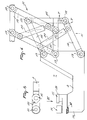
- Figure 4 is a schematic side view of a robot arm in a milking position.
- the robot arm 8 is connected to the frame 13 of the milkbox 1 via the parallelogram constructions 11, 10 and 9 (non-shown in the present figure; see Figures 1 - 3).
- the parallelogram construction 9 ensures substantially the movement of the robot arm in the longitudinal direction of the milkbox 1.
- the parallelogram constructions 10 and 11 allow a movement perpendicular to said longitudinal direction and predominantly horizontal, vertical respectively.
- the parallelogram constructions 9, 10 and 11 each comprise four arms 18 which are arranged in the shape of a parallelogram via hinge points 19. Furthermore controllable servo-pneumatic (and/or servo-hydraulic) cylinders 20 are hingeably fastened to two opposite sides of the parallelogram, in such a manner that the relevant parallelogram construction is movable by a movement of the piston in the cylinder 20.
- the robot arm 8 is provided with a milking member 14 and a separate pre-treatment member 15, the latter being fastened to the robot arm 8 so as to be movable relative to the milking member 14.
- the pre-treatment member 15 is rotatably disposed about a central axis of the almost cylindrical milking member 14, as will be explained in further detail with reference to Figure 7.
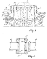
- FIG. 5 shows a cross-section taken on the line V - V in Figure 4.
- the hinge point 19 between the arms 18 of the parallelogram construction 11 is provided with ball bearings 21. Because of the small frictional forces in the ball bearings 21, the hinge point, and along therewith the entire parallelogram construction, can move more quickly, so that a quicker control of the milking robot 7 is possible.
- the upper arm 18 is bearing-supported in the hinge point 19 by means of a central pin, represented as a horizontal one, which is bearing-supported in the ball bearings 21 and which is rigidly connected to the upper arm 18.
- the hinge point 19 is further provided with a clinometer 22 that cooperates with the aforementioned pin. Consequently, a high degree of accuracy in the movement of the robot arm 8 can be obtained.
- Figure 6 shows a plan view of a detail of the robot arm of Figure 4 according to the arrow VI in said figure.
- the milking member 14, which is substantially cylindrical, and the pre-treatment member 15, which is substantially cylindrical as well, are fastened to the robot arm 8 so as to be almost parallel to each other, the pre-treatment member 15 being rotatably disposed around the milking member 14 and being provided with a supply line 23 for cleaning and/or disinfecting fluid for the relevant teat.
- the supply line 23 is provided with a connecting piece that is rotatably bearing-supported, as will be explained in further detail with reference to Figure 7.
- Figure 7 is a schematic cross-section taken on the line VII - VII in Figure 2.
- the end of the robot arm 8 is provided with a milking member 14 and a separate pre-treatment member 15 which is fastened to the robot arm 8 so as to be movable (rotatably or slidably) relative to the milking member 14.
- the pre-treatment member 15 is rotatably disposed about a central axis of the substantially cylindrical milking member 14.
- Each milking member 14 is adapted to milk one of the teats of the animal 3 to be milked and comprises for that purpose a teat cup 24 (known per se) for collecting and conveying the milk yielded, the inside of said teat cup 24 being provided with (non-shown) pulsation means, such as a flexible, transformable inner case which, with the aid of air-pressure changes produced by a pulsation line 25, alternately milks and releases the relevant teat.
- pulsation means such as a flexible, transformable inner case which, with the aid of air-pressure changes produced by a pulsation line 25, alternately milks and releases the relevant teat.
- a milk line 26 in which there is a permanent vacuum (i.e.
- the milk is discharged from the teat cup 24 to a valve 27 which, depending on a signal supplied by a milk quality sensor 28, guides the consumable milk into the production milk line 29 and the other substances (such as e.g. foremilk if any or cleaning fluid) into the residue line 30.
- a milk quality sensor 28 guides the consumable milk into the production milk line 29 and the other substances (such as e.g. foremilk if any or cleaning fluid) into the residue line 30.
- a motor 31 (e.g. a stepper motor) is adapted to drive an annular sleeve 32 that is rotatably bearing-supported around the teat cup 24, to which annular sleeve 32 the pre-treatment member 15 is fastened.
- Each of the pre-treatment members 15 is adapted to clean and/or to stimulate and/or to foremilk one of the teats of the animal 3 to be milked.
- the pre-treatment member 15 is provided with a movable, substantially cylindrical or conical case 33. This case 33 is movable in upward and downward direction or, like in the embodiment shown, rotatably bearing-supported in the housing 34 of the pre-treatment member 15 and drivable with the aid of a motor 35 (e.g. a stepper motor).
- the inside of the case 33 is provided with a profile 36 which extends substantially as a spiral.
- the inside of the case 33 preferably consists of a soft material, such as rubber or a soft synthetic material.
- the lower side of the pre-treatment member 15 is provided with a discharge opening 37 via which cleaning and/or disinfecting fluid and/or foremilk if any can be discharged without the milking member 14 being contaminated.
- the teat opening of the milking member 14 and that of the pre-treatment member 15 are located almost at the same level.
- the supply line 23 for cleaning and/or disinfecting fluid is provided with a connecting piece 38 which is rotatably bearing-supported and whose orientation at a rotation of the pre-treatment member 15 around the milking member 14 remains almost equal.
- the connecting piece 38 can be bearing-supported so as to be slidable as well, in order to avoid problems with the supply line 23 at a sliding movement of the pre-treatment member 15.
- the robot arm 8 is shown in a pre-treatment position: the teat can be pre-treated in the pre-treatment member 15.
- the pre-treatment stage has ended, in the subsequent milking stage the milking member 14 is connected to the relevant teat by the control mechanism.
- said pre-treatment member 15 is rotated away by means of the motor 31, whereafter the robot arm 8 brings the milking member 14 to the place that was previously occupied by the pre-treatment member 15.
- This positioning is very simple because of the fact that the position of the pre-treatment member 15 is already known. By rotating the pre-treatment member 15 away, the latter is prevented from forming an obstacle in the milking stage and e.g. from obstructing the other robot arms 8.
- the robot arm 8 is shown in a milking position: the pre-treatment member 15 has been rotated away and the teat can be milked in the milking member 14.
- the pre-treatment member 15 is pivoted back into the position shown in Figure 7 by means of the motor 31.
- FIG 8 shows schematically another embodiment of the implement.
- Two robot arms 8 are each provided with two milking members 14 and two separate pre-treatment members 15.
- This embodiment has the advantage that the pre-treatment stage can be performed quickly.
- the control is simple because of the fact that there are provided only two robot arms 8.
- the movable pre-treatment members 15 enable a highly accurate and quick positioning.
- the implement according to the invention makes it possible to perform the pre-treatment stage quickly and efficiently while making use of simple means. Furthermore the pre-treatment stage and the milking stage for different teats can be performed in a different manner and be attuned to the specific conditions. Moreover, because of the mutual movability of the pre-treatment member 15 and the milking member 14, the robot arms 8 are compact and not unnecessarily large in size.
Landscapes
- Life Sciences & Earth Sciences (AREA)
- Animal Husbandry (AREA)
- Environmental Sciences (AREA)
- External Artificial Organs (AREA)
- Cleaning In General (AREA)
- Catching Or Destruction (AREA)
- Manipulator (AREA)
Applications Claiming Priority (3)
| Application Number | Priority Date | Filing Date | Title |
|---|---|---|---|
| NL1007642 | 1997-11-28 | ||
| NL1007642A NL1007642C2 (nl) | 1997-11-28 | 1997-11-28 | Inrichting voor het melken van dieren. |
| EP98957230A EP0963153B1 (de) | 1997-11-28 | 1998-11-25 | Vorrichtung zum melken von tieren |
Related Parent Applications (1)
| Application Number | Title | Priority Date | Filing Date |
|---|---|---|---|
| EP98957230A Division EP0963153B1 (de) | 1997-11-28 | 1998-11-25 | Vorrichtung zum melken von tieren |
Publications (2)
| Publication Number | Publication Date |
|---|---|
| EP1247445A2 true EP1247445A2 (de) | 2002-10-09 |
| EP1247445A3 EP1247445A3 (de) | 2003-04-16 |
Family
ID=19766076
Family Applications (2)
| Application Number | Title | Priority Date | Filing Date |
|---|---|---|---|
| EP02077630A Withdrawn EP1247445A3 (de) | 1997-11-28 | 1998-11-25 | Vorrichtung zum Melken von Tieren |
| EP98957230A Expired - Lifetime EP0963153B1 (de) | 1997-11-28 | 1998-11-25 | Vorrichtung zum melken von tieren |
Family Applications After (1)
| Application Number | Title | Priority Date | Filing Date |
|---|---|---|---|
| EP98957230A Expired - Lifetime EP0963153B1 (de) | 1997-11-28 | 1998-11-25 | Vorrichtung zum melken von tieren |
Country Status (5)
| Country | Link |
|---|---|
| EP (2) | EP1247445A3 (de) |
| JP (1) | JP2001509683A (de) |
| DE (1) | DE69813188T2 (de) |
| NL (1) | NL1007642C2 (de) |
| WO (1) | WO1999027770A1 (de) |
Families Citing this family (3)
| Publication number | Priority date | Publication date | Assignee | Title |
|---|---|---|---|---|
| SE9903857D0 (sv) * | 1999-10-26 | 1999-10-26 | Alfa Laval Agri Ab | Means for improved milking |
| NL1014781C2 (nl) * | 2000-03-29 | 2001-03-05 | Idento Electronics Bv | Melkinrichting met voorbehandelsysteem. |
| SE516961C2 (sv) * | 2000-07-26 | 2002-03-26 | Delaval Holding Ab | Förfarande och anordning för spenkoppspåsättning |
Family Cites Families (4)
| Publication number | Priority date | Publication date | Assignee | Title |
|---|---|---|---|---|
| NL9401681A (nl) * | 1994-10-12 | 1996-05-01 | Maasland Nv | Werkwijze en inrichting voor het automatisch melken van dieren, zoals koeien. |
| NL9500364A (nl) * | 1995-02-24 | 1996-10-01 | Maasland Nv | Inrichting voor het melken van dieren. |
| NL1002319C2 (nl) * | 1996-02-13 | 1997-08-14 | Maasland Nv | Inrichting voor het automatisch melken van dieren. |
| EP0801893B1 (de) * | 1996-04-17 | 2002-09-18 | Maasland N.V. | Gerät zum Melken von Tieren, sowie Kühen |
-
1997
- 1997-11-28 NL NL1007642A patent/NL1007642C2/nl not_active IP Right Cessation
-
1998
- 1998-11-25 EP EP02077630A patent/EP1247445A3/de not_active Withdrawn
- 1998-11-25 JP JP53069399A patent/JP2001509683A/ja active Pending
- 1998-11-25 EP EP98957230A patent/EP0963153B1/de not_active Expired - Lifetime
- 1998-11-25 DE DE69813188T patent/DE69813188T2/de not_active Expired - Lifetime
- 1998-11-25 WO PCT/NL1998/000669 patent/WO1999027770A1/en not_active Ceased
Also Published As
| Publication number | Publication date |
|---|---|
| EP1247445A3 (de) | 2003-04-16 |
| EP0963153B1 (de) | 2003-04-09 |
| WO1999027770A1 (en) | 1999-06-10 |
| NL1007642C2 (nl) | 1999-05-31 |
| DE69813188T2 (de) | 2004-01-29 |
| DE69813188D1 (de) | 2003-05-15 |
| EP0963153A1 (de) | 1999-12-15 |
| JP2001509683A (ja) | 2001-07-24 |
Similar Documents
| Publication | Publication Date | Title |
|---|---|---|
| EP0551960B1 (de) | Vorrichtung zum automatischen Melken von Tieren | |
| EP0349019B1 (de) | Gerät zum Melken von Tieren | |
| US6279507B1 (en) | Construction including an implement for automatically milking animals | |
| US5784994A (en) | Apparatus and method for automatically milking animals | |
| US8646410B2 (en) | Automatic milking device | |
| EP0728412B1 (de) | Vorrichtung zum Melken von Tieren | |
| EP0332235B1 (de) | Gerät zum automatischen Melken von Tieren | |
| US10357015B2 (en) | Robotic arm with double grabber and method of operation | |
| US9615537B2 (en) | Milking box with backplane responsive robotic attacher | |
| EP1131997A2 (de) | Konstruktion mit Vorrichtung zum Melken von Tieren | |
| AU595362B2 (en) | An implement for milking animals | |
| EP0647390B1 (de) | Konstruktion zum automatischen Melken von Tieren | |
| EP0258938B2 (de) | Gerät zum Melken von Tieren | |
| EP0963153B1 (de) | Vorrichtung zum melken von tieren | |
| EP0990387B1 (de) | Vorrichtung zum Melken von Tieren | |
| EP0880888A2 (de) | Vorrichtung zum automatischen Melken von Tieren | |
| EP1172029B1 (de) | Konstruktion zum automatischen Melken von Tieren | |
| EP0647391B1 (de) | Konstruktion zum automatischen Melken von Tieren | |
| EP0962131B1 (de) | Verfahren zum Melken von Tieren | |
| EP0673596B1 (de) | Konstruktion mit Gerät zum Melken von Tieren | |
| EP0638232B1 (de) | Vorrichtung zum automatischen Melken von Tieren | |
| EP1252817A2 (de) | Konstruktion mit einem Gerät zum automatischen Melken von Tieren |
Legal Events
| Date | Code | Title | Description |
|---|---|---|---|
| PUAI | Public reference made under article 153(3) epc to a published international application that has entered the european phase |
Free format text: ORIGINAL CODE: 0009012 |
|
| AC | Divisional application: reference to earlier application |
Ref document number: 963153 Country of ref document: EP |
|
| AK | Designated contracting states |
Kind code of ref document: A2 Designated state(s): BE CH DE FR GB IT LI NL SE |
|
| PUAL | Search report despatched |
Free format text: ORIGINAL CODE: 0009013 |
|
| AK | Designated contracting states |
Designated state(s): BE CH DE FR GB IT LI NL SE |
|
| RIC1 | Information provided on ipc code assigned before grant |
Ipc: 7A 01J 7/04 B Ipc: 7A 01J 5/017 A |
|
| 17P | Request for examination filed |
Effective date: 20030716 |
|
| 17Q | First examination report despatched |
Effective date: 20030930 |
|
| AKX | Designation fees paid |
Designated state(s): BE CH DE FR GB IT LI NL SE |
|
| STAA | Information on the status of an ep patent application or granted ep patent |
Free format text: STATUS: THE APPLICATION IS DEEMED TO BE WITHDRAWN |
|
| 18D | Application deemed to be withdrawn |
Effective date: 20040211 |