EP1246979B1 - Verstärkter pfosten mit vorrichtung zur verankerung - Google Patents
Verstärkter pfosten mit vorrichtung zur verankerung Download PDFInfo
- Publication number
- EP1246979B1 EP1246979B1 EP00935829A EP00935829A EP1246979B1 EP 1246979 B1 EP1246979 B1 EP 1246979B1 EP 00935829 A EP00935829 A EP 00935829A EP 00935829 A EP00935829 A EP 00935829A EP 1246979 B1 EP1246979 B1 EP 1246979B1
- Authority
- EP
- European Patent Office
- Prior art keywords
- pole
- holes
- base plate
- concrete
- parking meter
- Prior art date
- Legal status (The legal status is an assumption and is not a legal conclusion. Google has not performed a legal analysis and makes no representation as to the accuracy of the status listed.)
- Expired - Lifetime
Links
- 238000004873 anchoring Methods 0.000 title claims abstract description 15
- 239000004567 concrete Substances 0.000 claims abstract description 23
- 229910052751 metal Inorganic materials 0.000 claims abstract description 23
- 239000002184 metal Substances 0.000 claims abstract description 23
- 239000004593 Epoxy Substances 0.000 claims abstract description 18
- 239000007787 solid Substances 0.000 claims abstract description 9
- 230000000717 retained effect Effects 0.000 claims description 8
- 238000003466 welding Methods 0.000 abstract description 9
- 150000001875 compounds Chemical class 0.000 abstract description 7
- 238000000034 method Methods 0.000 abstract description 6
- 229910000679 solder Inorganic materials 0.000 abstract description 2
- JEIPFZHSYJVQDO-UHFFFAOYSA-N iron(III) oxide Inorganic materials O=[Fe]O[Fe]=O JEIPFZHSYJVQDO-UHFFFAOYSA-N 0.000 abstract 1
- 229920000915 polyvinyl chloride Polymers 0.000 description 17
- 239000004800 polyvinyl chloride Substances 0.000 description 17
- 238000005552 hardfacing Methods 0.000 description 15
- 229910000831 Steel Inorganic materials 0.000 description 5
- 239000010959 steel Substances 0.000 description 5
- OKTJSMMVPCPJKN-UHFFFAOYSA-N Carbon Chemical compound [C] OKTJSMMVPCPJKN-UHFFFAOYSA-N 0.000 description 3
- 239000000835 fiber Substances 0.000 description 2
- 229910002804 graphite Inorganic materials 0.000 description 2
- 239000010439 graphite Substances 0.000 description 2
- 239000011440 grout Substances 0.000 description 2
- ZOXJGFHDIHLPTG-UHFFFAOYSA-N Boron Chemical compound [B] ZOXJGFHDIHLPTG-UHFFFAOYSA-N 0.000 description 1
- VYZAMTAEIAYCRO-UHFFFAOYSA-N Chromium Chemical compound [Cr] VYZAMTAEIAYCRO-UHFFFAOYSA-N 0.000 description 1
- 229910001209 Low-carbon steel Inorganic materials 0.000 description 1
- ZOKXTWBITQBERF-UHFFFAOYSA-N Molybdenum Chemical compound [Mo] ZOKXTWBITQBERF-UHFFFAOYSA-N 0.000 description 1
- XUIMIQQOPSSXEZ-UHFFFAOYSA-N Silicon Chemical compound [Si] XUIMIQQOPSSXEZ-UHFFFAOYSA-N 0.000 description 1
- 229910045601 alloy Inorganic materials 0.000 description 1
- 239000000956 alloy Substances 0.000 description 1
- 230000000712 assembly Effects 0.000 description 1
- 238000000429 assembly Methods 0.000 description 1
- 239000011230 binding agent Substances 0.000 description 1
- 229910052796 boron Inorganic materials 0.000 description 1
- 239000011449 brick Substances 0.000 description 1
- 229910052799 carbon Inorganic materials 0.000 description 1
- 239000003054 catalyst Substances 0.000 description 1
- 229910052804 chromium Inorganic materials 0.000 description 1
- 239000011651 chromium Substances 0.000 description 1
- 230000006835 compression Effects 0.000 description 1
- 238000007906 compression Methods 0.000 description 1
- 239000004020 conductor Substances 0.000 description 1
- 230000005611 electricity Effects 0.000 description 1
- 229920006335 epoxy glue Polymers 0.000 description 1
- 230000005484 gravity Effects 0.000 description 1
- 239000011261 inert gas Substances 0.000 description 1
- WPBNNNQJVZRUHP-UHFFFAOYSA-L manganese(2+);methyl n-[[2-(methoxycarbonylcarbamothioylamino)phenyl]carbamothioyl]carbamate;n-[2-(sulfidocarbothioylamino)ethyl]carbamodithioate Chemical compound [Mn+2].[S-]C(=S)NCCNC([S-])=S.COC(=O)NC(=S)NC1=CC=CC=C1NC(=S)NC(=O)OC WPBNNNQJVZRUHP-UHFFFAOYSA-L 0.000 description 1
- 239000007769 metal material Substances 0.000 description 1
- 229910052750 molybdenum Inorganic materials 0.000 description 1
- 239000011733 molybdenum Substances 0.000 description 1
- 239000011150 reinforced concrete Substances 0.000 description 1
- 239000011435 rock Substances 0.000 description 1
- 229910052710 silicon Inorganic materials 0.000 description 1
- 239000010703 silicon Substances 0.000 description 1
- 239000002904 solvent Substances 0.000 description 1
- 239000000126 substance Substances 0.000 description 1
- 229910052720 vanadium Inorganic materials 0.000 description 1
- GPPXJZIENCGNKB-UHFFFAOYSA-N vanadium Chemical compound [V]#[V] GPPXJZIENCGNKB-UHFFFAOYSA-N 0.000 description 1
Images







Classifications
-
- E—FIXED CONSTRUCTIONS
- E04—BUILDING
- E04C—STRUCTURAL ELEMENTS; BUILDING MATERIALS
- E04C3/00—Structural elongated elements designed for load-supporting
- E04C3/02—Joists; Girders, trusses, or trusslike structures, e.g. prefabricated; Lintels; Transoms; Braces
- E04C3/29—Joists; Girders, trusses, or trusslike structures, e.g. prefabricated; Lintels; Transoms; Braces built-up from parts of different material, i.e. composite structures
-
- E—FIXED CONSTRUCTIONS
- E01—CONSTRUCTION OF ROADS, RAILWAYS, OR BRIDGES
- E01F—ADDITIONAL WORK, SUCH AS EQUIPPING ROADS OR THE CONSTRUCTION OF PLATFORMS, HELICOPTER LANDING STAGES, SIGNS, SNOW FENCES, OR THE LIKE
- E01F9/00—Arrangement of road signs or traffic signals; Arrangements for enforcing caution
- E01F9/60—Upright bodies, e.g. marker posts or bollards; Supports for road signs
- E01F9/658—Upright bodies, e.g. marker posts or bollards; Supports for road signs characterised by means for fixing
- E01F9/673—Upright bodies, e.g. marker posts or bollards; Supports for road signs characterised by means for fixing for holding sign posts or the like
- E01F9/675—Glued to surface, e.g. road
-
- E—FIXED CONSTRUCTIONS
- E01—CONSTRUCTION OF ROADS, RAILWAYS, OR BRIDGES
- E01F—ADDITIONAL WORK, SUCH AS EQUIPPING ROADS OR THE CONSTRUCTION OF PLATFORMS, HELICOPTER LANDING STAGES, SIGNS, SNOW FENCES, OR THE LIKE
- E01F9/00—Arrangement of road signs or traffic signals; Arrangements for enforcing caution
- E01F9/60—Upright bodies, e.g. marker posts or bollards; Supports for road signs
- E01F9/658—Upright bodies, e.g. marker posts or bollards; Supports for road signs characterised by means for fixing
- E01F9/673—Upright bodies, e.g. marker posts or bollards; Supports for road signs characterised by means for fixing for holding sign posts or the like
- E01F9/685—Subsoil means, e.g. foundations
-
- E—FIXED CONSTRUCTIONS
- E04—BUILDING
- E04H—BUILDINGS OR LIKE STRUCTURES FOR PARTICULAR PURPOSES; SWIMMING OR SPLASH BATHS OR POOLS; MASTS; FENCING; TENTS OR CANOPIES, IN GENERAL
- E04H12/00—Towers; Masts or poles; Chimney stacks; Water-towers; Methods of erecting such structures
- E04H12/22—Sockets or holders for poles or posts
- E04H12/2253—Mounting poles or posts to the holder
- E04H12/2261—Mounting poles or posts to the holder on a flat base
-
- E—FIXED CONSTRUCTIONS
- E04—BUILDING
- E04H—BUILDINGS OR LIKE STRUCTURES FOR PARTICULAR PURPOSES; SWIMMING OR SPLASH BATHS OR POOLS; MASTS; FENCING; TENTS OR CANOPIES, IN GENERAL
- E04H12/00—Towers; Masts or poles; Chimney stacks; Water-towers; Methods of erecting such structures
- E04H12/22—Sockets or holders for poles or posts
- E04H12/2292—Holders used for protection, repair or reinforcement of the post or pole
Definitions
- the present invention relates to an apparatus for anchoring parking meter poles in concrete.
- U.S. Patent No. 265,106 issued on September 26, 1882, to Robert Bristow Lee, discloses a device for forming lattice pillars, in which wire is wrapped around a cylindrical object in a spiral pattern.
- the instant invention is distinguishable, in that the hard-facing is welded to the pole in vertical strips.
- U.S. Patent No. 1,842,547 issued on January 26, 1932, to Victor F. Hammel, discloses a cylindrical structure, in which a post or pole is supported by helically arranged bars or rods. Again, the instant invention is distinguishable, in that the hard-facing is welded to the pole in vertical strips.
- U.S. Patent No. 3,349,531 issued on October 31, 1967, to George H. Watson, discloses a frangible connector assembly for stanchions, poles, and standards, which may be used in parking meter poles, in which an anchoring bolt is embedded in concrete.
- the instant invention is distinguishable, in that in it the anchoring tubes are attached to the concrete by epoxy.
- U.S. Patent No. 3,972,529 issued on August 3, 1976, to Walter F. McNeil, discloses reinforced tubular metallic materials, having recesses cut along their outer surfaces, into which graphite fiber strips are inserted.
- the instant invention is distinguishable, in that in it a hardening compound, rather than graphite fiber, is applied over the surface of the parking meter poles, rather than in recesses.
- U.S. Patent No. 4,986,406, issued on January 22, 1991, to B. Drew Winsor discloses an anti-theft parking meter anchoring device, for anchoring a parking meter head to the top of a support post, by means of a locking pin that passes through transverse holes in the bottom of the parking meter head and the top of the support post.
- the instant invention is distinguishable, as it uses welding to secure the parking meter head on the support post, and does not require a locking pin.
- U.S. Patent No. 5,666, 774 issued on September 16, 1997, to Alfred D. Commins, discloses an adjustable support system for joining structural members, in which a threaded rod is secured in concrete by grout or epoxy.
- the instant invention is distinguishable, in that in it tubes or rods are welded to the base plate, need not be threaded, and in a preferred embodiment have hollow interiors to allow more effective bonding to the hardened epoxy.
- the instant invention is distinguishable, in that it reinforces the pole to which the head of the parking meter is attached, and strengthens the connection of the pole to the head by welding.
- U.S. Patent No. 5,806,262 issued on September 15, 1998, to Gordon A. Nagle, discloses a post and a method of emplacing the post in concrete.
- the instant invention is distinguishable, in that it uses epoxy to bind the metal cylinders in the base plate to a concrete surface.
- U.S. Patent No. 5,878,540 issued on March 9, 1999, to Jerome Neil Morstein, discloses a utility pole base pan with drain, involving the embedding of metal bolts in concrete, without the use of epoxy, as in the instant invention.
- holes are drilled in a concrete surface, epoxy is inserted into the holes, and the metal cylinders are inserted into the holes before the epoxy hardens.
- circular transverse holes are made in the top of the pole using a plasma cutter, and expander jaws are then welded to the interior of the pole, to securely attach the head of the parking meter to the pole.
- Still another object of the invention is to provide a means for securely attaching any upright object to a concrete surface.
- the present invention is designed primarily to prevent theft from parking meters, though it may also have other applications.
- Fig. 1 is a front elevational view of the preferred embodiment of the invention, before the polyvinyl chloride ("PVC") pipe and parking meter head are attached.
- the invention is retained on a concrete surface 10, into which holes 12 have been drilled. (Alternatively, the invention could be retained on another solid surface, such as rock or brick, or the holes could be formed by another method, such as the use of molds when the concrete is first poured.)
- a pipe 14 is welded to the top of a base plate 16. Tubes 18 are welded to the bottom of the base plate.
- the pipe, base plate and tubes are all made of mild steel.
- a hard-facing compound is applied to the surface of the pipe, preferably in vertical strips by arc welding.
- the hard-facing compound is preferably an alloy containing carbon, chromium, molybdenum, manganese, silicon, boron and vanadium, having a Rockwell hardness number of at least 60. (Such hard-facing compounds are commercially available.)
- the strips of hard-facing should run from the bottom end of the pipe to almost the top of the pipe, but should end a short distance from the top to allow the parking meter head to be inserted over the pipe.
- the strips of hard-facing are difficult to cut through without the use of conspicuous special equipment that would attract the attention of authorities, thus preventing theft of coins in the parking meter by cutting through the pipe and taking the head to a private location where the coins can be removed.
- Fig. 2 is a top plan view of the steel pipe 14 reinforced by the strips of hard-facing 20, showing the pipes hollow interior 22.
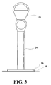
- Fig. 3 is a front elevation view of the preferred embodiment of the invention, after the PVC pipe 24 and parking meter head 26 have been attached.
- two parking meter heads may be attached to the same pole (not shown in the drawings).
- the purpose of the PVC pipe is to improve the appearance of the parking meter, to prevent damage from chains used with bicycle locks, and to provide a maintenance-free surface.
- a pipe made of any other suitable waterproof substance could be used.
- Fig. 4 is a top plan view, showing the metal pipe 14 with its hollow interior 22 and the strips of hard-facing 20, surrounded by the PVC pipe 24.
- the interior surface of the PVC pipe should just touch the hard-facing, leaving a small gap 28 between the metal pipe and the PVC pipe.
- one of the following three methods may be used to bond the interior surface of the PVC pipe to the hard-facing: (1) the metal pipe with the hard-facing is heated in an oven or by a blow torch, before placing the PVC pipe over it; (2) the PVC pipe is placed over the metal pipe before the hard-facing has cooled; or (3) a solvent is applied to the interior surface of the PVC pipe before it is placed over the metal pipe and the hard-facing.
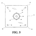
- Fig. 5 is a top plan view of the preferred embodiment of the invention, before the PVC pipe and parking meter head are attached, showing four holes 30 that are drilled through the base plate 16 above the centers of the tubes welded to the other side of the plate. Also shown is a metal disk 34 that is welded inside the metal pipe near its top end. The disk has a threaded hole 36 through which a bolt (not shown in the drawings) is inserted to retain the parking meter head on the pole.
- the corners 32 of the base plate should be rounded.
- Fig. 6 is a bottom plan view of the preferred embodiment of the invention, showing the hollow interiors 37 of the tubes 18 welded to the base plate 16.
- one tube should be adjacent to each corner of the base plate.
- the base plate should be square, but rectangular, triangular, polygonal, circular and other shapes of base plates are within the scope of the invention.
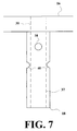
- Fig. 7 is a detail view of one of the tubes 18 attached to the base plate 18.
- the hollow interior 37 of the tube and the hole 30 through the base plate are indicated by broken lines.
- transverse holes 38 and 40 drilled through the tube, at right angles to the axis of the tube and to each other.
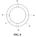
- Fig. 8 is a bottom plan view of one of the tubes attached to the base plate, with the transverse holes 38 and 40 drilled through the tube at right angles indicated by broken lines.
- the binder and catalyst of epoxy glue are mixed and then injected into the holes in the concrete (or other solid surface), and the tubes (or other anchoring elements) are then inserted into the holes.
- the hollow interiors and transverse holes of the tubes, and the holes in the base plate serve to increase the surface area to which the epoxy can bind, thus increasing the strength of the bond between the metal and concrete.
- the holes in the base plate also allow air to escape from the tubes.
- the epoxy should be smoothed off at the tops of the holes in the base plate before it hardens, so that the epoxy filled holes will not be readily apparent.
- This method makes it possible to securely attach a parking meter (or other upright object, such as a stop sign or lamp post) to concrete, without having to drill several feet down (which could interfere with utility lines).
- a parking meter or other upright object, such as a stop sign or lamp post
- Another advantage of this method is that parking meters have a low enough center of gravity that other means of support are not necessary while the epoxy hardens. With larger objects, such as lamp posts, external support may be necessary while the epoxy hardens.
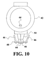
- Fig. 9 through 11 illustrate the way that parking meter heads are generally retained on their supporting poles in parking meters currently in use.
- Fig. 9 is a perspective view of a lower housing 42 of the parking meter head, a bolt 44, three expander jaws 46, and an expander nut 48, before they are assembled.
- An upper housing and cap assembly (not shown in the drawings) are attached to the lower housing to complete the parking meter head.
- the lower housing has a bottom portion 50 with preferably three outward sloping surfaces 52 (only two of which are visible in Fig. 9).
- the bolt has a head 54 and a shaft 56 with male threading 58 that can engage female threading (not shown in the drawings) in the hole 60 in the expander nut.
- the expander jaws are preferably flat metal objects with narrow tops 62 and wide bottoms 64, with notches 66 in the bottoms.
- the expander nut has one projection 68 for each expander jaw.
- Parking meters currently on the market have three expander jaws; but this aspect of the invention can apply to parking meters (or other objects with similar connecting features) with any number of expander jaws.
- the number of outwardly sloping surfaces on the bottom portion of the lower housing should preferably be equal to the number of jaws.
- Fig. 10 is a front elevational view of the lower housing, a bolt, three expander jaws, and an expander nut, after they have been assembled, but before the jaws have been expanded.
- the expander jaws are attached to the expander nut by fitting the projections of the expander nut into the notches of each of the expander jaws.
- the bolt is then inserted through a hole (not shown in the drawings) in the bottom center of the lower housing, brought in contact with the expander nut, and turned so that the male threads on the bolt engage the females threads in the hole of the expander nut, thus retaining the expander nut on the bolt.
- the lower housing, with the expander jaws which are retained on the expander nut which is retained by the bolt on the housing is then placed over the top of the pole. Then the bolt is turned again to expand the jaws.
- Fig. 11 is a bottom plan view, looking upwards from a horizontal cross-section of the steel pipe or other pole, showing how the expander jaws are positioned when they have been fully expanded by turning the bolt.
- the bolt is turned, the expander nut and the jaws attached to it are pulled toward the bottom portion of the lower housing, thus bringing the jaws in contact with its outwardly sloping surfaces, so that the tops of the jaws are pushed outward until they contact the interior surface of the pole.
- the bolt is then tightened so that the jaws are firmly wedged between the interior surface 22 of the pole 14 and the outwardly sloping surfaces of the bottom portion of the lower housing.
- friction between the jaws and these surfaces is usually the only means by which the head is retained on the pole. Thus, it is easy for thieves to pry the head off the pole.
- Fig. 12 is a bottom plan view, showing the holes 70 made through the pole, and the welds 72 between the top portions of the expander jaws and the interior of the pole.
- a plasma-arc cutter is used to make the holes.
- Plasma-arc cutters and welders use gasses that are superheated until they are in a plasma state, where electrons are stripped off nuclei of atoms in the gasses, so that normally insulating gasses become conductors of electricity.
- Plasma-arc cutters can form holes in metal more quickly and accurately than conventional metal cutting torches.
- the same plasma-arc equipment may be used for both cutting and welding metal.
- a plasma-arc welder, or a MIG (Metal Inert Gas) welder or any other suitable welding equipment may be used to weld the top of the jaw to the interior surface of the pipe.
- the jaw may also be welded to the bottom of the lower housing.
- Metal in a welding wire may be melted by the welder to complete the weld.
- the hole may be then be filled in with more metal from the welding wire or solder.
- the holes with not be visible anyway.
Landscapes
- Engineering & Computer Science (AREA)
- Architecture (AREA)
- Civil Engineering (AREA)
- Structural Engineering (AREA)
- Chemical & Material Sciences (AREA)
- Composite Materials (AREA)
- Refuge Islands, Traffic Blockers, Or Guard Fence (AREA)
- Road Signs Or Road Markings (AREA)
- Piles And Underground Anchors (AREA)
- Joining Of Building Structures In Genera (AREA)
- Load-Engaging Elements For Cranes (AREA)
- Dowels (AREA)
- Foundations (AREA)
Claims (4)
- Struktur zum Halten eines Säulenelements auf einer festen Fläche, umfassend:eine Grundplatte (16) mit einer Oberseite und einer Unterseite;eine Vorrichtung zum Fixieren eines Säulenelements auf der Oberseite der Grundplatte;Verankerungselemente (18), die an der Unterseite der Grundplatte fixiert sind; undLöcher (12) in der festen Fläche, dadurch gekennzeichnet, dass die Verankerungselemente (18) in den Löchern (12) mittels Epoxydharz fixiert werden, wobei die Verankerungselemente (18) Röhren mit Innenhohlräumen (37) sind, wobei Löcher (40) an den Seiten der Verankerungselemente ausgebildet sind, wobei diese Löcher (40) von einer Außenseite des Verankerungselements (18) in den Innenhohlraum (37) verlaufen.
- Struktur zum Halten eines Säulenelements auf einer festen Fläche gemäß Anspruch 1, wobei die Grundplatte (16) und die Verankerungselemente (18) aus Metall gefertigt sind, und die Verankerungselemente an der Grundplatte angeschweißt sind.
- Struktur zum Halten eines Säulenelements auf einer festen Fläche gemäß Anspruch 2, wobei die feste Fläche aus Beton besteht.
- Struktur zum Halten eines Säulenelements auf einer festen Fläche gemäß Anspruch 1, wobei das Säulenelement an der Grundplatte (16) angeschweißt ist.
Applications Claiming Priority (5)
| Application Number | Priority Date | Filing Date | Title |
|---|---|---|---|
| US09/317,830 US6202371B1 (en) | 1999-05-25 | 1999-05-25 | Reinforced pole with apparatus and method for anchoring |
| US317830 | 1999-05-25 | ||
| US404579 | 1999-09-24 | ||
| US09/404,579 US6282861B1 (en) | 1999-05-25 | 1999-09-24 | Reinforced pole with apparatus and method for anchoring |
| PCT/US2000/009822 WO2000071830A1 (en) | 1999-05-25 | 2000-05-24 | Reinforced pole with apparatus and method for anchoring |
Publications (3)
| Publication Number | Publication Date |
|---|---|
| EP1246979A1 EP1246979A1 (de) | 2002-10-09 |
| EP1246979A4 EP1246979A4 (de) | 2004-05-06 |
| EP1246979B1 true EP1246979B1 (de) | 2007-03-14 |
Family
ID=26981170
Family Applications (1)
| Application Number | Title | Priority Date | Filing Date |
|---|---|---|---|
| EP00935829A Expired - Lifetime EP1246979B1 (de) | 1999-05-25 | 2000-05-24 | Verstärkter pfosten mit vorrichtung zur verankerung |
Country Status (10)
| Country | Link |
|---|---|
| US (1) | US6282861B1 (de) |
| EP (1) | EP1246979B1 (de) |
| AT (1) | ATE356912T1 (de) |
| AU (1) | AU5123000A (de) |
| BR (1) | BR0011547A (de) |
| CA (1) | CA2404766A1 (de) |
| DE (1) | DE60033966T2 (de) |
| ES (1) | ES2283302T3 (de) |
| MX (1) | MXPA01012023A (de) |
| WO (1) | WO2000071830A1 (de) |
Families Citing this family (15)
| Publication number | Priority date | Publication date | Assignee | Title |
|---|---|---|---|---|
| FR2818334A1 (fr) * | 2000-12-20 | 2002-06-21 | Metal Services Etudes Realisat | Ancre pour l'accrochage d'un antivol |
| US6439344B1 (en) * | 2001-01-26 | 2002-08-27 | Mc Enterprises International, Inc. | Concrete mounted safety stanchion and apparatus and methods for mounting to concrete |
| US6640517B2 (en) * | 2001-06-26 | 2003-11-04 | Ruud Lighting, Inc. | Pole mounting system having unique base and method of assembly thereof |
| AUPR745001A0 (en) * | 2001-09-04 | 2001-09-27 | John Holland Pty Ltd | A method for reinforcing poles |
| CA2422750C (en) * | 2003-03-12 | 2012-05-01 | Simon Walker | Rail and railing system |
| US20050144888A1 (en) * | 2003-12-19 | 2005-07-07 | Mark Snyders | Ground mounting fixture |
| CA2460983C (en) * | 2004-03-26 | 2012-05-15 | Simon Walker | Picket for a railing system |
| CA2462360C (en) * | 2004-04-01 | 2010-08-03 | Simon Walker | Post system for a railing |
| CN2736477Y (zh) * | 2004-09-30 | 2005-10-26 | 马准安 | 一种篷结构 |
| USD547463S1 (en) * | 2006-04-03 | 2007-07-24 | Peak Innovations Inc. | Post anchor |
| US9004439B2 (en) * | 2006-04-04 | 2015-04-14 | Peak Innovations Inc. | Post anchor |
| GB201003274D0 (en) * | 2010-02-26 | 2010-04-14 | A Fax Ltd | Methods of connecting |
| CN105953033B (zh) * | 2016-05-09 | 2018-05-22 | 江苏大学 | 底部结构可调的防霜机支座 |
| US11492818B1 (en) * | 2021-01-23 | 2022-11-08 | Julian McVay | Post repair and reinforcement apparatus |
| DE102023120767A1 (de) | 2023-08-04 | 2025-02-06 | Bernhard Rimbach | Vorrichtung zur Sicherung eines Schafts gegen Herausschieben aus einer den Schaft radial umfassenden Schaftaufnahme, Schaft und mobiles Verkehrszeichen |
Family Cites Families (22)
| Publication number | Priority date | Publication date | Assignee | Title |
|---|---|---|---|---|
| US265106A (en) | 1882-09-26 | Device foe fobming lattice hllabs | ||
| US885158A (en) | 1907-10-24 | 1908-04-21 | Trussed Concrete Steel Co | Expanded metal. |
| US1842547A (en) | 1930-10-24 | 1932-01-26 | Victor F Hammel | Cylindrical structure |
| US3349531A (en) | 1964-07-16 | 1967-10-31 | George H Watson | Frangible connector assembly for stanchions, poles and standards |
| US3621663A (en) * | 1969-03-13 | 1971-11-23 | Akemasa Otani | Ribbed pile |
| CA885158A (en) | 1970-04-10 | 1971-11-09 | D. George Joseph | Pole installation |
| US3792680A (en) * | 1971-06-07 | 1974-02-19 | F Allen | Flag pole |
| SE389705B (sv) * | 1972-08-25 | 1976-11-15 | L Svensson | Stolpe |
| GB1358432A (en) * | 1972-11-24 | 1974-07-03 | Production Mfg Services Ltd | Means for anchoring posts and the like |
| US3972529A (en) | 1974-10-07 | 1976-08-03 | Mcneil Walter F | Reinforced tubular materials and process |
| US4798273A (en) * | 1986-11-06 | 1989-01-17 | Pom Incorporated | Parking meter anchor |
| FR2624903A1 (fr) | 1987-12-16 | 1989-06-23 | Champy Louis | Procede pour la pose de pylones et dispositif s'y rapportant |
| US4986406A (en) | 1989-10-05 | 1991-01-22 | Winsor B Drew | Anti-theft parking meter anchoring device |
| DE9305861U1 (de) * | 1993-04-20 | 1993-06-24 | H. Debuschewitz GmbH & Co KG, 5000 Köln | Geldautomatenpfosten |
| US5586417A (en) | 1994-11-23 | 1996-12-24 | Henderson; Allan P. | Tensionless pier foundation |
| FR2735823B1 (fr) | 1995-06-22 | 1997-09-05 | Valeo | Embrayage a friction a dispositif de rattrapage de jeu, notamment pour vehicule automobile |
| US5666774A (en) | 1995-06-30 | 1997-09-16 | Simpson Strong-Tie Company, Inc. | Adjustable support system |
| US5806262A (en) | 1995-12-05 | 1998-09-15 | Schuylkill Products, Inc. | Post and method of emplacing a post |
| US6098361A (en) * | 1996-04-24 | 2000-08-08 | Pom, Inc. | Parking meter anchor system |
| USD396655S (en) * | 1996-07-10 | 1998-08-04 | Reset (Aust) Pty Ltd | Pedestal for a parking meter |
| US5803228A (en) | 1996-09-26 | 1998-09-08 | Lucas; Tom | Parking meter assemblies |
| US5878540A (en) | 1997-09-12 | 1999-03-09 | Site Photometrics, Inc. | Utility pole base pan with drain |
-
1999
- 1999-09-24 US US09/404,579 patent/US6282861B1/en not_active Expired - Lifetime
-
2000
- 2000-05-24 AU AU51230/00A patent/AU5123000A/en not_active Abandoned
- 2000-05-24 EP EP00935829A patent/EP1246979B1/de not_active Expired - Lifetime
- 2000-05-24 ES ES00935829T patent/ES2283302T3/es not_active Expired - Lifetime
- 2000-05-24 DE DE60033966T patent/DE60033966T2/de not_active Expired - Lifetime
- 2000-05-24 WO PCT/US2000/009822 patent/WO2000071830A1/en not_active Ceased
- 2000-05-24 CA CA002404766A patent/CA2404766A1/en not_active Abandoned
- 2000-05-24 MX MXPA01012023A patent/MXPA01012023A/es unknown
- 2000-05-24 BR BR0011547-9A patent/BR0011547A/pt not_active Application Discontinuation
- 2000-05-24 AT AT00935829T patent/ATE356912T1/de not_active IP Right Cessation
Also Published As
| Publication number | Publication date |
|---|---|
| MXPA01012023A (es) | 2003-09-04 |
| ES2283302T3 (es) | 2007-11-01 |
| BR0011547A (pt) | 2002-02-26 |
| EP1246979A1 (de) | 2002-10-09 |
| US6282861B1 (en) | 2001-09-04 |
| AU5123000A (en) | 2000-12-12 |
| ATE356912T1 (de) | 2007-04-15 |
| DE60033966T2 (de) | 2008-02-14 |
| CA2404766A1 (en) | 2000-11-30 |
| DE60033966D1 (de) | 2007-04-26 |
| EP1246979A4 (de) | 2004-05-06 |
| WO2000071830A1 (en) | 2000-11-30 |
Similar Documents
| Publication | Publication Date | Title |
|---|---|---|
| US6446411B2 (en) | Reinforced pole with apparatus and method for anchoring | |
| US6282861B1 (en) | Reinforced pole with apparatus and method for anchoring | |
| US5060435A (en) | Bracket for support of vertical pole | |
| CA2966172C (en) | Single anchor terminal | |
| US6202371B1 (en) | Reinforced pole with apparatus and method for anchoring | |
| JP2011080195A (ja) | アンカー装置およびアンカーの施工法 | |
| JP2023115887A (ja) | 支柱固定方法 | |
| US20020189193A1 (en) | Barrier cable end bracket assembly | |
| EP1397562B1 (de) | Bodenverankerungsvorrichtung | |
| KR200469905Y1 (ko) | 야외시설물 설치용 기초파일 및 그 시공에 사용되는 설치가이드대 | |
| CN103233474B (zh) | 立柱结构及包括该立柱结构的基坑支护系统 | |
| JP2005240426A (ja) | 鋼管柱の立設構造 | |
| JP5111481B2 (ja) | 支柱支持方法 | |
| CN210831633U (zh) | 一种灯杆易安装结构及照明系统 | |
| CN215888009U (zh) | 一种市政道路路口用限高装置 | |
| CN221621369U (zh) | 一种定位装置 | |
| JP2983496B2 (ja) | 転落防止設備 | |
| JP2000355917A (ja) | 防護柵の基礎および防護柵の支持構造 | |
| CN212927366U (zh) | 一种工地可重复使用的装配式钢筋混凝土围挡防溢底座 | |
| US4317643A (en) | Steel reinforced concrete piles | |
| CN221030200U (zh) | 一种钢管柱与预制方桩的连接件及组合支撑立柱 | |
| CN115434310B (zh) | Phc斜管桩断后补张拉连接装置和施工方法 | |
| JP2007277897A (ja) | 雪崩・落石等防護体の支柱連結具 | |
| JP3066458U (ja) | 工事用フェンスの支持台 | |
| CN121161727A (zh) | 预制桥梁临边防护立杆系统及其施工方法 |
Legal Events
| Date | Code | Title | Description |
|---|---|---|---|
| PUAI | Public reference made under article 153(3) epc to a published international application that has entered the european phase |
Free format text: ORIGINAL CODE: 0009012 |
|
| 17P | Request for examination filed |
Effective date: 20011221 |
|
| AK | Designated contracting states |
Kind code of ref document: A1 Designated state(s): AT BE CH CY DE DK ES FI FR GB GR IE IT LI LU MC NL PT SE |
|
| A4 | Supplementary search report drawn up and despatched |
Effective date: 20040318 |
|
| RIC1 | Information provided on ipc code assigned before grant |
Ipc: 7E 04H 12/22 B Ipc: 7E 01F 9/011 B Ipc: 7E 04C 3/00 A |
|
| GRAP | Despatch of communication of intention to grant a patent |
Free format text: ORIGINAL CODE: EPIDOSNIGR1 |
|
| RTI1 | Title (correction) |
Free format text: REINFORCED POLE WITH APPARATUS FOR ANCHORING |
|
| GRAS | Grant fee paid |
Free format text: ORIGINAL CODE: EPIDOSNIGR3 |
|
| GRAA | (expected) grant |
Free format text: ORIGINAL CODE: 0009210 |
|
| AK | Designated contracting states |
Kind code of ref document: B1 Designated state(s): AT BE CH CY DE DK ES FI FR GB GR IE IT LI LU MC NL PT SE |
|
| PG25 | Lapsed in a contracting state [announced via postgrant information from national office to epo] |
Ref country code: CH Free format text: LAPSE BECAUSE OF FAILURE TO SUBMIT A TRANSLATION OF THE DESCRIPTION OR TO PAY THE FEE WITHIN THE PRESCRIBED TIME-LIMIT Effective date: 20070314 Ref country code: LI Free format text: LAPSE BECAUSE OF FAILURE TO SUBMIT A TRANSLATION OF THE DESCRIPTION OR TO PAY THE FEE WITHIN THE PRESCRIBED TIME-LIMIT Effective date: 20070314 Ref country code: BE Free format text: LAPSE BECAUSE OF FAILURE TO SUBMIT A TRANSLATION OF THE DESCRIPTION OR TO PAY THE FEE WITHIN THE PRESCRIBED TIME-LIMIT Effective date: 20070314 Ref country code: FI Free format text: LAPSE BECAUSE OF FAILURE TO SUBMIT A TRANSLATION OF THE DESCRIPTION OR TO PAY THE FEE WITHIN THE PRESCRIBED TIME-LIMIT Effective date: 20070314 Ref country code: AT Free format text: LAPSE BECAUSE OF FAILURE TO SUBMIT A TRANSLATION OF THE DESCRIPTION OR TO PAY THE FEE WITHIN THE PRESCRIBED TIME-LIMIT Effective date: 20070314 |
|
| REG | Reference to a national code |
Ref country code: GB Ref legal event code: FG4D |
|
| REG | Reference to a national code |
Ref country code: CH Ref legal event code: EP |
|
| REF | Corresponds to: |
Ref document number: 60033966 Country of ref document: DE Date of ref document: 20070426 Kind code of ref document: P |
|
| REG | Reference to a national code |
Ref country code: IE Ref legal event code: FG4D |
|
| PG25 | Lapsed in a contracting state [announced via postgrant information from national office to epo] |
Ref country code: SE Free format text: LAPSE BECAUSE OF FAILURE TO SUBMIT A TRANSLATION OF THE DESCRIPTION OR TO PAY THE FEE WITHIN THE PRESCRIBED TIME-LIMIT Effective date: 20070614 |
|
| PG25 | Lapsed in a contracting state [announced via postgrant information from national office to epo] |
Ref country code: PT Free format text: LAPSE BECAUSE OF FAILURE TO SUBMIT A TRANSLATION OF THE DESCRIPTION OR TO PAY THE FEE WITHIN THE PRESCRIBED TIME-LIMIT Effective date: 20070814 |
|
| ET | Fr: translation filed | ||
| REG | Reference to a national code |
Ref country code: CH Ref legal event code: PL |
|
| REG | Reference to a national code |
Ref country code: ES Ref legal event code: FG2A Ref document number: 2283302 Country of ref document: ES Kind code of ref document: T3 |
|
| PLBE | No opposition filed within time limit |
Free format text: ORIGINAL CODE: 0009261 |
|
| STAA | Information on the status of an ep patent application or granted ep patent |
Free format text: STATUS: NO OPPOSITION FILED WITHIN TIME LIMIT |
|
| PG25 | Lapsed in a contracting state [announced via postgrant information from national office to epo] |
Ref country code: DK Free format text: LAPSE BECAUSE OF FAILURE TO SUBMIT A TRANSLATION OF THE DESCRIPTION OR TO PAY THE FEE WITHIN THE PRESCRIBED TIME-LIMIT Effective date: 20070314 Ref country code: MC Free format text: LAPSE BECAUSE OF NON-PAYMENT OF DUE FEES Effective date: 20070531 |
|
| 26N | No opposition filed |
Effective date: 20071217 |
|
| PG25 | Lapsed in a contracting state [announced via postgrant information from national office to epo] |
Ref country code: GR Free format text: LAPSE BECAUSE OF FAILURE TO SUBMIT A TRANSLATION OF THE DESCRIPTION OR TO PAY THE FEE WITHIN THE PRESCRIBED TIME-LIMIT Effective date: 20070615 |
|
| PG25 | Lapsed in a contracting state [announced via postgrant information from national office to epo] |
Ref country code: IE Free format text: LAPSE BECAUSE OF NON-PAYMENT OF DUE FEES Effective date: 20070524 |
|
| PG25 | Lapsed in a contracting state [announced via postgrant information from national office to epo] |
Ref country code: CY Free format text: LAPSE BECAUSE OF FAILURE TO SUBMIT A TRANSLATION OF THE DESCRIPTION OR TO PAY THE FEE WITHIN THE PRESCRIBED TIME-LIMIT Effective date: 20070314 |
|
| PG25 | Lapsed in a contracting state [announced via postgrant information from national office to epo] |
Ref country code: LU Free format text: LAPSE BECAUSE OF NON-PAYMENT OF DUE FEES Effective date: 20070524 |
|
| PGFP | Annual fee paid to national office [announced via postgrant information from national office to epo] |
Ref country code: FR Payment date: 20110615 Year of fee payment: 12 Ref country code: ES Payment date: 20110615 Year of fee payment: 12 |
|
| PGFP | Annual fee paid to national office [announced via postgrant information from national office to epo] |
Ref country code: GB Payment date: 20110601 Year of fee payment: 12 Ref country code: NL Payment date: 20110601 Year of fee payment: 12 |
|
| PGFP | Annual fee paid to national office [announced via postgrant information from national office to epo] |
Ref country code: DE Payment date: 20110531 Year of fee payment: 12 Ref country code: IT Payment date: 20110530 Year of fee payment: 12 |
|
| REG | Reference to a national code |
Ref country code: NL Ref legal event code: V1 Effective date: 20121201 |
|
| GBPC | Gb: european patent ceased through non-payment of renewal fee |
Effective date: 20120524 |
|
| PG25 | Lapsed in a contracting state [announced via postgrant information from national office to epo] |
Ref country code: IT Free format text: LAPSE BECAUSE OF NON-PAYMENT OF DUE FEES Effective date: 20120524 |
|
| REG | Reference to a national code |
Ref country code: FR Ref legal event code: ST Effective date: 20130131 |
|
| REG | Reference to a national code |
Ref country code: DE Ref legal event code: R119 Ref document number: 60033966 Country of ref document: DE Effective date: 20121201 |
|
| PG25 | Lapsed in a contracting state [announced via postgrant information from national office to epo] |
Ref country code: NL Free format text: LAPSE BECAUSE OF NON-PAYMENT OF DUE FEES Effective date: 20121201 |
|
| PG25 | Lapsed in a contracting state [announced via postgrant information from national office to epo] |
Ref country code: GB Free format text: LAPSE BECAUSE OF NON-PAYMENT OF DUE FEES Effective date: 20120524 Ref country code: FR Free format text: LAPSE BECAUSE OF NON-PAYMENT OF DUE FEES Effective date: 20120531 |
|
| PG25 | Lapsed in a contracting state [announced via postgrant information from national office to epo] |
Ref country code: DE Free format text: LAPSE BECAUSE OF NON-PAYMENT OF DUE FEES Effective date: 20121201 |
|
| REG | Reference to a national code |
Ref country code: ES Ref legal event code: FD2A Effective date: 20130820 |
|
| PG25 | Lapsed in a contracting state [announced via postgrant information from national office to epo] |
Ref country code: ES Free format text: LAPSE BECAUSE OF NON-PAYMENT OF DUE FEES Effective date: 20120525 |