EP1246236A1 - Semiconductor chip carrying adhesive tape/sheet, semiconductor chip carrier, semiconductor chip mounting method and semiconductor chip packaging body - Google Patents
Semiconductor chip carrying adhesive tape/sheet, semiconductor chip carrier, semiconductor chip mounting method and semiconductor chip packaging body Download PDFInfo
- Publication number
- EP1246236A1 EP1246236A1 EP02252236A EP02252236A EP1246236A1 EP 1246236 A1 EP1246236 A1 EP 1246236A1 EP 02252236 A EP02252236 A EP 02252236A EP 02252236 A EP02252236 A EP 02252236A EP 1246236 A1 EP1246236 A1 EP 1246236A1
- Authority
- EP
- European Patent Office
- Prior art keywords
- semiconductor chip
- adhesive agent
- cover member
- semiconductor
- adhering
- Prior art date
- Legal status (The legal status is an assumption and is not a legal conclusion. Google has not performed a legal analysis and makes no representation as to the accuracy of the status listed.)
- Withdrawn
Links
Images


Classifications
-
- H—ELECTRICITY
- H01—ELECTRIC ELEMENTS
- H01L—SEMICONDUCTOR DEVICES NOT COVERED BY CLASS H10
- H01L21/00—Processes or apparatus adapted for the manufacture or treatment of semiconductor or solid state devices or of parts thereof
- H01L21/67—Apparatus specially adapted for handling semiconductor or electric solid state devices during manufacture or treatment thereof; Apparatus specially adapted for handling wafers during manufacture or treatment of semiconductor or electric solid state devices or components ; Apparatus not specifically provided for elsewhere
- H01L21/683—Apparatus specially adapted for handling semiconductor or electric solid state devices during manufacture or treatment thereof; Apparatus specially adapted for handling wafers during manufacture or treatment of semiconductor or electric solid state devices or components ; Apparatus not specifically provided for elsewhere for supporting or gripping
- H01L21/6835—Apparatus specially adapted for handling semiconductor or electric solid state devices during manufacture or treatment thereof; Apparatus specially adapted for handling wafers during manufacture or treatment of semiconductor or electric solid state devices or components ; Apparatus not specifically provided for elsewhere for supporting or gripping using temporarily an auxiliary support
- H01L21/6836—Wafer tapes, e.g. grinding or dicing support tapes
-
- C—CHEMISTRY; METALLURGY
- C09—DYES; PAINTS; POLISHES; NATURAL RESINS; ADHESIVES; COMPOSITIONS NOT OTHERWISE PROVIDED FOR; APPLICATIONS OF MATERIALS NOT OTHERWISE PROVIDED FOR
- C09J—ADHESIVES; NON-MECHANICAL ASPECTS OF ADHESIVE PROCESSES IN GENERAL; ADHESIVE PROCESSES NOT PROVIDED FOR ELSEWHERE; USE OF MATERIALS AS ADHESIVES
- C09J7/00—Adhesives in the form of films or foils
- C09J7/20—Adhesives in the form of films or foils characterised by their carriers
-
- H—ELECTRICITY
- H01—ELECTRIC ELEMENTS
- H01L—SEMICONDUCTOR DEVICES NOT COVERED BY CLASS H10
- H01L23/00—Details of semiconductor or other solid state devices
- H01L23/02—Containers; Seals
- H01L23/10—Containers; Seals characterised by the material or arrangement of seals between parts, e.g. between cap and base of the container or between leads and walls of the container
-
- H—ELECTRICITY
- H01—ELECTRIC ELEMENTS
- H01L—SEMICONDUCTOR DEVICES NOT COVERED BY CLASS H10
- H01L24/00—Arrangements for connecting or disconnecting semiconductor or solid-state bodies; Methods or apparatus related thereto
- H01L24/01—Means for bonding being attached to, or being formed on, the surface to be connected, e.g. chip-to-package, die-attach, "first-level" interconnects; Manufacturing methods related thereto
- H01L24/26—Layer connectors, e.g. plate connectors, solder or adhesive layers; Manufacturing methods related thereto
- H01L24/28—Structure, shape, material or disposition of the layer connectors prior to the connecting process
- H01L24/29—Structure, shape, material or disposition of the layer connectors prior to the connecting process of an individual layer connector
-
- H—ELECTRICITY
- H01—ELECTRIC ELEMENTS
- H01L—SEMICONDUCTOR DEVICES NOT COVERED BY CLASS H10
- H01L24/00—Arrangements for connecting or disconnecting semiconductor or solid-state bodies; Methods or apparatus related thereto
- H01L24/80—Methods for connecting semiconductor or other solid state bodies using means for bonding being attached to, or being formed on, the surface to be connected
- H01L24/83—Methods for connecting semiconductor or other solid state bodies using means for bonding being attached to, or being formed on, the surface to be connected using a layer connector
-
- H—ELECTRICITY
- H01—ELECTRIC ELEMENTS
- H01L—SEMICONDUCTOR DEVICES NOT COVERED BY CLASS H10
- H01L24/00—Arrangements for connecting or disconnecting semiconductor or solid-state bodies; Methods or apparatus related thereto
- H01L24/93—Batch processes
- H01L24/95—Batch processes at chip-level, i.e. with connecting carried out on a plurality of singulated devices, i.e. on diced chips
- H01L24/97—Batch processes at chip-level, i.e. with connecting carried out on a plurality of singulated devices, i.e. on diced chips the devices being connected to a common substrate, e.g. interposer, said common substrate being separable into individual assemblies after connecting
-
- C—CHEMISTRY; METALLURGY
- C09—DYES; PAINTS; POLISHES; NATURAL RESINS; ADHESIVES; COMPOSITIONS NOT OTHERWISE PROVIDED FOR; APPLICATIONS OF MATERIALS NOT OTHERWISE PROVIDED FOR
- C09J—ADHESIVES; NON-MECHANICAL ASPECTS OF ADHESIVE PROCESSES IN GENERAL; ADHESIVE PROCESSES NOT PROVIDED FOR ELSEWHERE; USE OF MATERIALS AS ADHESIVES
- C09J2203/00—Applications of adhesives in processes or use of adhesives in the form of films or foils
- C09J2203/326—Applications of adhesives in processes or use of adhesives in the form of films or foils for bonding electronic components such as wafers, chips or semiconductors
-
- C—CHEMISTRY; METALLURGY
- C09—DYES; PAINTS; POLISHES; NATURAL RESINS; ADHESIVES; COMPOSITIONS NOT OTHERWISE PROVIDED FOR; APPLICATIONS OF MATERIALS NOT OTHERWISE PROVIDED FOR
- C09J—ADHESIVES; NON-MECHANICAL ASPECTS OF ADHESIVE PROCESSES IN GENERAL; ADHESIVE PROCESSES NOT PROVIDED FOR ELSEWHERE; USE OF MATERIALS AS ADHESIVES
- C09J2301/00—Additional features of adhesives in the form of films or foils
- C09J2301/20—Additional features of adhesives in the form of films or foils characterized by the structural features of the adhesive itself
- C09J2301/204—Additional features of adhesives in the form of films or foils characterized by the structural features of the adhesive itself the adhesive coating being discontinuous
-
- H—ELECTRICITY
- H01—ELECTRIC ELEMENTS
- H01L—SEMICONDUCTOR DEVICES NOT COVERED BY CLASS H10
- H01L2221/00—Processes or apparatus adapted for the manufacture or treatment of semiconductor or solid state devices or of parts thereof covered by H01L21/00
- H01L2221/67—Apparatus for handling semiconductor or electric solid state devices during manufacture or treatment thereof; Apparatus for handling wafers during manufacture or treatment of semiconductor or electric solid state devices or components; Apparatus not specifically provided for elsewhere
- H01L2221/683—Apparatus for handling semiconductor or electric solid state devices during manufacture or treatment thereof; Apparatus for handling wafers during manufacture or treatment of semiconductor or electric solid state devices or components; Apparatus not specifically provided for elsewhere for supporting or gripping
- H01L2221/68304—Apparatus for handling semiconductor or electric solid state devices during manufacture or treatment thereof; Apparatus for handling wafers during manufacture or treatment of semiconductor or electric solid state devices or components; Apparatus not specifically provided for elsewhere for supporting or gripping using temporarily an auxiliary support
- H01L2221/68327—Apparatus for handling semiconductor or electric solid state devices during manufacture or treatment thereof; Apparatus for handling wafers during manufacture or treatment of semiconductor or electric solid state devices or components; Apparatus not specifically provided for elsewhere for supporting or gripping using temporarily an auxiliary support used during dicing or grinding
-
- H—ELECTRICITY
- H01—ELECTRIC ELEMENTS
- H01L—SEMICONDUCTOR DEVICES NOT COVERED BY CLASS H10
- H01L2221/00—Processes or apparatus adapted for the manufacture or treatment of semiconductor or solid state devices or of parts thereof covered by H01L21/00
- H01L2221/67—Apparatus for handling semiconductor or electric solid state devices during manufacture or treatment thereof; Apparatus for handling wafers during manufacture or treatment of semiconductor or electric solid state devices or components; Apparatus not specifically provided for elsewhere
- H01L2221/683—Apparatus for handling semiconductor or electric solid state devices during manufacture or treatment thereof; Apparatus for handling wafers during manufacture or treatment of semiconductor or electric solid state devices or components; Apparatus not specifically provided for elsewhere for supporting or gripping
- H01L2221/68304—Apparatus for handling semiconductor or electric solid state devices during manufacture or treatment thereof; Apparatus for handling wafers during manufacture or treatment of semiconductor or electric solid state devices or components; Apparatus not specifically provided for elsewhere for supporting or gripping using temporarily an auxiliary support
- H01L2221/68359—Apparatus for handling semiconductor or electric solid state devices during manufacture or treatment thereof; Apparatus for handling wafers during manufacture or treatment of semiconductor or electric solid state devices or components; Apparatus not specifically provided for elsewhere for supporting or gripping using temporarily an auxiliary support used as a support during manufacture of interconnect decals or build up layers
-
- H—ELECTRICITY
- H01—ELECTRIC ELEMENTS
- H01L—SEMICONDUCTOR DEVICES NOT COVERED BY CLASS H10
- H01L2224/00—Indexing scheme for arrangements for connecting or disconnecting semiconductor or solid-state bodies and methods related thereto as covered by H01L24/00
- H01L2224/01—Means for bonding being attached to, or being formed on, the surface to be connected, e.g. chip-to-package, die-attach, "first-level" interconnects; Manufacturing methods related thereto
- H01L2224/26—Layer connectors, e.g. plate connectors, solder or adhesive layers; Manufacturing methods related thereto
- H01L2224/28—Structure, shape, material or disposition of the layer connectors prior to the connecting process
- H01L2224/29—Structure, shape, material or disposition of the layer connectors prior to the connecting process of an individual layer connector
- H01L2224/29001—Core members of the layer connector
- H01L2224/29099—Material
- H01L2224/2919—Material with a principal constituent of the material being a polymer, e.g. polyester, phenolic based polymer, epoxy
-
- H—ELECTRICITY
- H01—ELECTRIC ELEMENTS
- H01L—SEMICONDUCTOR DEVICES NOT COVERED BY CLASS H10
- H01L2224/00—Indexing scheme for arrangements for connecting or disconnecting semiconductor or solid-state bodies and methods related thereto as covered by H01L24/00
- H01L2224/80—Methods for connecting semiconductor or other solid state bodies using means for bonding being attached to, or being formed on, the surface to be connected
- H01L2224/83—Methods for connecting semiconductor or other solid state bodies using means for bonding being attached to, or being formed on, the surface to be connected using a layer connector
- H01L2224/8319—Arrangement of the layer connectors prior to mounting
- H01L2224/83192—Arrangement of the layer connectors prior to mounting wherein the layer connectors are disposed only on another item or body to be connected to the semiconductor or solid-state body
-
- H—ELECTRICITY
- H01—ELECTRIC ELEMENTS
- H01L—SEMICONDUCTOR DEVICES NOT COVERED BY CLASS H10
- H01L2224/00—Indexing scheme for arrangements for connecting or disconnecting semiconductor or solid-state bodies and methods related thereto as covered by H01L24/00
- H01L2224/80—Methods for connecting semiconductor or other solid state bodies using means for bonding being attached to, or being formed on, the surface to be connected
- H01L2224/83—Methods for connecting semiconductor or other solid state bodies using means for bonding being attached to, or being formed on, the surface to be connected using a layer connector
- H01L2224/838—Bonding techniques
- H01L2224/8385—Bonding techniques using a polymer adhesive, e.g. an adhesive based on silicone, epoxy, polyimide, polyester
-
- H—ELECTRICITY
- H01—ELECTRIC ELEMENTS
- H01L—SEMICONDUCTOR DEVICES NOT COVERED BY CLASS H10
- H01L2224/00—Indexing scheme for arrangements for connecting or disconnecting semiconductor or solid-state bodies and methods related thereto as covered by H01L24/00
- H01L2224/93—Batch processes
- H01L2224/95—Batch processes at chip-level, i.e. with connecting carried out on a plurality of singulated devices, i.e. on diced chips
- H01L2224/97—Batch processes at chip-level, i.e. with connecting carried out on a plurality of singulated devices, i.e. on diced chips the devices being connected to a common substrate, e.g. interposer, said common substrate being separable into individual assemblies after connecting
-
- H—ELECTRICITY
- H01—ELECTRIC ELEMENTS
- H01L—SEMICONDUCTOR DEVICES NOT COVERED BY CLASS H10
- H01L2924/00—Indexing scheme for arrangements or methods for connecting or disconnecting semiconductor or solid-state bodies as covered by H01L24/00
- H01L2924/01—Chemical elements
- H01L2924/01004—Beryllium [Be]
-
- H—ELECTRICITY
- H01—ELECTRIC ELEMENTS
- H01L—SEMICONDUCTOR DEVICES NOT COVERED BY CLASS H10
- H01L2924/00—Indexing scheme for arrangements or methods for connecting or disconnecting semiconductor or solid-state bodies as covered by H01L24/00
- H01L2924/01—Chemical elements
- H01L2924/01005—Boron [B]
-
- H—ELECTRICITY
- H01—ELECTRIC ELEMENTS
- H01L—SEMICONDUCTOR DEVICES NOT COVERED BY CLASS H10
- H01L2924/00—Indexing scheme for arrangements or methods for connecting or disconnecting semiconductor or solid-state bodies as covered by H01L24/00
- H01L2924/01—Chemical elements
- H01L2924/01006—Carbon [C]
-
- H—ELECTRICITY
- H01—ELECTRIC ELEMENTS
- H01L—SEMICONDUCTOR DEVICES NOT COVERED BY CLASS H10
- H01L2924/00—Indexing scheme for arrangements or methods for connecting or disconnecting semiconductor or solid-state bodies as covered by H01L24/00
- H01L2924/01—Chemical elements
- H01L2924/01012—Magnesium [Mg]
-
- H—ELECTRICITY
- H01—ELECTRIC ELEMENTS
- H01L—SEMICONDUCTOR DEVICES NOT COVERED BY CLASS H10
- H01L2924/00—Indexing scheme for arrangements or methods for connecting or disconnecting semiconductor or solid-state bodies as covered by H01L24/00
- H01L2924/01—Chemical elements
- H01L2924/01013—Aluminum [Al]
-
- H—ELECTRICITY
- H01—ELECTRIC ELEMENTS
- H01L—SEMICONDUCTOR DEVICES NOT COVERED BY CLASS H10
- H01L2924/00—Indexing scheme for arrangements or methods for connecting or disconnecting semiconductor or solid-state bodies as covered by H01L24/00
- H01L2924/01—Chemical elements
- H01L2924/01015—Phosphorus [P]
-
- H—ELECTRICITY
- H01—ELECTRIC ELEMENTS
- H01L—SEMICONDUCTOR DEVICES NOT COVERED BY CLASS H10
- H01L2924/00—Indexing scheme for arrangements or methods for connecting or disconnecting semiconductor or solid-state bodies as covered by H01L24/00
- H01L2924/01—Chemical elements
- H01L2924/01027—Cobalt [Co]
-
- H—ELECTRICITY
- H01—ELECTRIC ELEMENTS
- H01L—SEMICONDUCTOR DEVICES NOT COVERED BY CLASS H10
- H01L2924/00—Indexing scheme for arrangements or methods for connecting or disconnecting semiconductor or solid-state bodies as covered by H01L24/00
- H01L2924/01—Chemical elements
- H01L2924/01029—Copper [Cu]
-
- H—ELECTRICITY
- H01—ELECTRIC ELEMENTS
- H01L—SEMICONDUCTOR DEVICES NOT COVERED BY CLASS H10
- H01L2924/00—Indexing scheme for arrangements or methods for connecting or disconnecting semiconductor or solid-state bodies as covered by H01L24/00
- H01L2924/01—Chemical elements
- H01L2924/01033—Arsenic [As]
-
- H—ELECTRICITY
- H01—ELECTRIC ELEMENTS
- H01L—SEMICONDUCTOR DEVICES NOT COVERED BY CLASS H10
- H01L2924/00—Indexing scheme for arrangements or methods for connecting or disconnecting semiconductor or solid-state bodies as covered by H01L24/00
- H01L2924/01—Chemical elements
- H01L2924/01047—Silver [Ag]
-
- H—ELECTRICITY
- H01—ELECTRIC ELEMENTS
- H01L—SEMICONDUCTOR DEVICES NOT COVERED BY CLASS H10
- H01L2924/00—Indexing scheme for arrangements or methods for connecting or disconnecting semiconductor or solid-state bodies as covered by H01L24/00
- H01L2924/01—Chemical elements
- H01L2924/0105—Tin [Sn]
-
- H—ELECTRICITY
- H01—ELECTRIC ELEMENTS
- H01L—SEMICONDUCTOR DEVICES NOT COVERED BY CLASS H10
- H01L2924/00—Indexing scheme for arrangements or methods for connecting or disconnecting semiconductor or solid-state bodies as covered by H01L24/00
- H01L2924/01—Chemical elements
- H01L2924/01079—Gold [Au]
-
- H—ELECTRICITY
- H01—ELECTRIC ELEMENTS
- H01L—SEMICONDUCTOR DEVICES NOT COVERED BY CLASS H10
- H01L2924/00—Indexing scheme for arrangements or methods for connecting or disconnecting semiconductor or solid-state bodies as covered by H01L24/00
- H01L2924/01—Chemical elements
- H01L2924/01082—Lead [Pb]
-
- H—ELECTRICITY
- H01—ELECTRIC ELEMENTS
- H01L—SEMICONDUCTOR DEVICES NOT COVERED BY CLASS H10
- H01L2924/00—Indexing scheme for arrangements or methods for connecting or disconnecting semiconductor or solid-state bodies as covered by H01L24/00
- H01L2924/013—Alloys
- H01L2924/014—Solder alloys
-
- H—ELECTRICITY
- H01—ELECTRIC ELEMENTS
- H01L—SEMICONDUCTOR DEVICES NOT COVERED BY CLASS H10
- H01L2924/00—Indexing scheme for arrangements or methods for connecting or disconnecting semiconductor or solid-state bodies as covered by H01L24/00
- H01L2924/06—Polymers
- H01L2924/0665—Epoxy resin
-
- H—ELECTRICITY
- H01—ELECTRIC ELEMENTS
- H01L—SEMICONDUCTOR DEVICES NOT COVERED BY CLASS H10
- H01L2924/00—Indexing scheme for arrangements or methods for connecting or disconnecting semiconductor or solid-state bodies as covered by H01L24/00
- H01L2924/06—Polymers
- H01L2924/078—Adhesive characteristics other than chemical
- H01L2924/07802—Adhesive characteristics other than chemical not being an ohmic electrical conductor
-
- H—ELECTRICITY
- H01—ELECTRIC ELEMENTS
- H01L—SEMICONDUCTOR DEVICES NOT COVERED BY CLASS H10
- H01L2924/00—Indexing scheme for arrangements or methods for connecting or disconnecting semiconductor or solid-state bodies as covered by H01L24/00
- H01L2924/10—Details of semiconductor or other solid state devices to be connected
- H01L2924/11—Device type
- H01L2924/12—Passive devices, e.g. 2 terminal devices
- H01L2924/1204—Optical Diode
- H01L2924/12041—LED
-
- H—ELECTRICITY
- H01—ELECTRIC ELEMENTS
- H01L—SEMICONDUCTOR DEVICES NOT COVERED BY CLASS H10
- H01L2924/00—Indexing scheme for arrangements or methods for connecting or disconnecting semiconductor or solid-state bodies as covered by H01L24/00
- H01L2924/15—Details of package parts other than the semiconductor or other solid state devices to be connected
- H01L2924/161—Cap
- H01L2924/1615—Shape
- H01L2924/16152—Cap comprising a cavity for hosting the device, e.g. U-shaped cap
-
- Y—GENERAL TAGGING OF NEW TECHNOLOGICAL DEVELOPMENTS; GENERAL TAGGING OF CROSS-SECTIONAL TECHNOLOGIES SPANNING OVER SEVERAL SECTIONS OF THE IPC; TECHNICAL SUBJECTS COVERED BY FORMER USPC CROSS-REFERENCE ART COLLECTIONS [XRACs] AND DIGESTS
- Y10—TECHNICAL SUBJECTS COVERED BY FORMER USPC
- Y10T—TECHNICAL SUBJECTS COVERED BY FORMER US CLASSIFICATION
- Y10T29/00—Metal working
- Y10T29/53—Means to assemble or disassemble
- Y10T29/5313—Means to assemble electrical device
- Y10T29/53174—Means to fasten electrical component to wiring board, base, or substrate
- Y10T29/53178—Chip component
Definitions
- the present invention relates to a semiconductor chip carrying adhesive tape/sheet, a semiconductor chip carrier and a semiconductor chip packaging body, to be used when mounting a semiconductor chip on a lead frame, or storing, transporting or automatically taking out the semiconductor chip before the mounting, and a method of producing the semiconductor chip carrier, a method of mounting the semiconductor chip and a method of packaging the semiconductor chip.
- the present invention was made in consideration with the above circumstances and has as an object thereof to provide a semiconductor chip carrying adhesive tape and sheet capable of improving an yield of adhesive agent attached chips and preventing wasteful use of an adhesive agent, a semiconductor chip carrier, a method of producing the same, a method of mounting the semiconductor chip, a semiconductor chip packaging body, and a method of packaging the semiconductor chip by using the semiconductor chip carrying adhesive tape or sheet.
- a semiconductor chip carrying adhesive tape wherein a plurality of adhesive agent portions for adhering a semiconductor chip are intermittently formed on a tape shaped base material in a longitudinal direction of the base material, in a substantially identical shape with that of the semiconductor chip to be adhered or a slightly larger shape than that of the semiconductor chip to be adhered, and an adhesive agent constituting the adhesive agent portions has gradable adhesiveness.
- the semiconductor carrying adhesive tape may be wound to be a wound body.
- a release film may be stuck on the surface of the semiconductor chip carrying adhesive tape.
- the adhesive agent which has gradable adhesiveness may have a stage of exhibiting tackiness (removable adhesiveness) and a stage of exhibiting adhesiveness (a so-called tacky adhesive agent), or may be those which do not exhibit any tackiness/adhesiveness in a normal state but exhibit gradable tackiness/adhesiveness by a heat, compression or other triggers.
- tacky adhesive agent a so-called tacky adhesive agent
- second adhesive agent portions for adhering a cover member may be adhered at both end portions of the tape shaped base material so as not to contact the adhesive agent portion for adhering the semiconductor chip.
- the adhesive force is controllable and selectable e.g. by controlling the temperature, pressure of contact, or by other conditions, depending on the type of gradable adhesive used (e.g. one which responds to heat, or is pressure-sensitive and so on).
- a semiconductor chip carrying adhesive sheet wherein a plurality of adhesive agent portions for adhering semiconductor chips are formed on a sheet shaped base material, in a substantially identical shape with that of the semiconductor chips to be adhered or a slightly larger shape than the semiconductor chips to be adhered, and an adhesive agent constituting the adhesive agent portions has gradable adhesiveness.
- a semiconductor chip carrier which can be obtained by sticking a semiconductor chip to the adhesive agent portion of the semiconductor chip carrying adhesive tape according to the above invention or to the adhesive agent portion of the semiconductor chip carrying adhesive sheet according to the above invention.
- a method of producing a semiconductor chip carrier comprising the step of; successively sticking the adhesive agent portions of the semiconductor chip carrying adhesive tape according to the above invention and the semiconductor chips arranged at predetermined intervals in turn, while moving the semiconductor chip carrying adhesive tape in the longitudinal direction.
- a method of mounting a semiconductor chip comprising the steps of; picking up a semiconductor chip together with an adhesive agent portion from the base material of the semiconductor chip carrier according to the above invention; and adhering the semiconductor chip to a lead frame via the adhesive agent portion.
- a first semiconductor chip packaging body which can be obtainable by adhering the semiconductor chip carrier according to the above invention and a continuous cover member on which a plurality of chip housings are intermittently formed in the longitudinal direction so that the semiconductor chips on the semiconductor chip carrier are housed in the chip housings on the cover member
- a second semiconductor chip packaging body which can be obtainable by adhering the semiconductor chip carrier according to the above invention and a tray shaped cover member on which a plurality of chip housings are formed so that the semiconductor chips on the semiconductor chip carrier are housed in the chip housings on the cover member.
- o adhering o here includes concepts of sticking, affixing and fusion bonding.
- a method of packaging a semiconductor chip comprising the step of; winding the semiconductor chip carrier according to the above invention and a tape shaped cover member on which a plurality of chip housings are intermittently formed in the longitudinal direction so that the semiconductor chips on the semiconductor chip carrier are housed in the chip housings of the cover member while adhering the semiconductor chip carrier and the tape shaped cover member.
- the semiconductor chip carrying adhesive tape or the semiconductor chip carrying adhesive sheet When using the semiconductor chip carrying adhesive tape or the semiconductor chip carrying adhesive sheet according to the present invention, since only non-defective semiconductor chips can be stuck to the adhesive agent portion for adhering the semiconductor chip of the semiconductor chip carrying adhesive tape or the semiconductor chip carrying adhesive sheet, a yield of adhesive agent attached semiconductor chips which should be mounted on a lead frame can be improved and a wasteful use of an adhesive agent can be prevented. Particularly, when the adhesive agent portion contains a conductive material made of a precious metal, such as Ag powders, costs for the adhesive agent can be considerably reduced comparing the case of sticking the adhesive agent portion allover the semiconductor wafer.
- the adhesive agent portion formed on the base material is formed in a substantially identical shape with that of a semiconductor chip to be adhered or a slightly larger shape than that of the semiconductor chip to be adhered, there is an advantage that cutting of the adhesive agent portion is not necessary.
- FIG. 1 is a perspective view of a semiconductor chip carrying adhesive tape according to a first embodiment of the present invention
- FIG. 2 is an overall perspective view of the semiconductor chip carrying adhesive tape according to the same embodiment
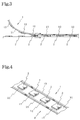
- FIG. 3 is a schematic side view when sticking the semiconductor chip carrying adhesive tape according to the same embodiment and a semiconductor chip
- FIG. 4 is a perspective view of a semiconductor chip carrier according to the same embodiment
- FIG. 5 is a perspective view of a cover member according to the same embodiment
- FIG. 6 is a schematic side view when adhering the semiconductor chip and the cover member carrier according to the same embodiment
- FIG. 7 is a schematic sectional view of a state where the semiconductor chip carrier and the cover member according to the same embodiment are adhered.
- a semiconductor chip carrying adhesive tape 1 according to a first embodiment of the present invention comprises a base material 11, a plurality of adhesive agent portions 12 for adhering to a semiconductor chip intermittently formed in the longitudinal direction of the base material 11, and adhesive agent portions 13 for adhering a cover member formed at both end portions of the base material 11.
- the adhesive agent portion 12 is made to have a substantially identical shape with that of a semiconductor chip to be adhered or a slightly larger shape than that of the semiconductor chip to be adhered, preferably, to have an identical shape with that of the semiconductor chip.
- the adhesive agent portion 12 is smaller than the semiconductor chip to be adhered, a space is formed in the semiconductor device when being encapsulated and reliability of the semiconductor device to be obtained declines.
- the adhesive agent portion 12 is too large, the semiconductor device cannot be made compact.
- a thickness of the adhesive agent portion 12 is normally 3 to 200 ⁇ m, preferably 5 to 100 ⁇ m.
- the adhesive agent portion 12 is comprised of an adhesive agent having gradable adhesiveness.
- the adhesive agents which exhibit gradable adhesiveness include those having a stage of tackiness (removable adhesiveness) and a stage of adhesiveness (a so-called tacky adhesive agent) and also include those which do not exhibit any tackiness/adhesiveness in a normal state but exhibit gradable tackiness/adhesiveness by a heat, compression or other triggers.
- An adhesive agent (tacky adhesive agent) of the former type may be, for example, a composition (a) containing a thermosetting resin and a tacky component, while an adhesive agent of the latter type may be, for example, a polyimide type resin (b) and an epoxy type resin (c), etc.
- the resins or the resin compositions may be used alone, or a material wherein the resin or the resin composition is used as a matrix can be also used.
- thermosetting resin exhibits adhesiveness and the tacky component exhibits tackiness.
- thermosetting resin in such a composition include an epoxy resin, a phenol resin, an urea resin, a melanin resin, an unsaturated polyester resin, a resorcinol resin, a furan resin, a polyurethane resin, a silicone resin etc.
- An epoxy resin is preferable among them.
- examples of the tacky component include an acrylic type adhesive, a rubber type adhesive, a polyester type adhesive, or thermoplastic resins such as polyolefin, polyvinyl chloride, polystyrene, thermoplastic polyamide and polyester.
- a photopolymerizable composition may be included therein.
- a tacky component a (meth)acrylate copolymer is preferable.
- composition A a composition containing a thermoplastic resin and a tacky component
- composition A a composition containing a (meth)acrylate copolymer having a weight-average molecular weight of not less than 30000, an epoxy resin having a weight-average molecular weight of 100 to 10000, a photopolymerizable low molecular compound and thermal activation latent epoxy resin curing agent.
- the (meth)acrylate copolymer having a weight-average molecular weight of not less than 30000 may be a copolymer obtained by copolymerizing monomers, such as, (meth)acrylic acid, for example, alkyl (meth)acrylate derived from (meth)acrylic acid and alcohol having a carbon number of 1 to 14, hydroxyethyl (meth)acrylate, glycidyl (meth)acrylate, etc.
- a copolymer of (meth)acrylic acid and/or glycidyl (meth)acrylic acid and at least one kind of alkyl (meth)acrylate is preferable among them.
- alkyl (meth)acrylate derived from (meth)acrylic acid and alcohol having a carbon number of 1 to 14 examples include methyl (meth)acrylate, ethyl (meth)acrylate, butyl (meth)acrylate, etc.
- a content of a component unit derived from glycidyl (meth)acrylic acid in the copolymer is normally made to be 0 to 80 mol%, preferably 5 to 50 mol%, and a content of a component unit derived from (meth)acrylic acid is normally made to be 0 to 40 mol%, preferably 5 to 20 mol%.
- alkyl (meth)acrylate such as, methyl (meth)acrylate, ethyl (meth)acrylate, butyl (meth)acrylate, etc.
- An epoxy resin having a weight-average molecular weight of 100 to 10000 may be glycidyl ether of a phenol series, such as, bisphenol A, bisphenol F, resorcinol, phenyl novolac, cresol novolac; glycidyl ether of an alcohol series, such as, butanediol, polyethylene glycol, polypropylene glycol; glycidyl ether of carboxylic acid, such as, phthalic acid, isophthalic acid, tetrahydro phthalic acid; a glycidyl type or alkyl glycidyl type epoxy resin obtained by substituting active hydrogen bonded with nitrogen atom, such as aniline isocyanurate, with a glycidyl group; and so-called alicycle epoxide wherein an epoxy group is introduced by, for example, oxidizing carbon-carbon double bond in molecular, such as, vinyl cyclohexene epoxide, 3,4
- An epoxy equivalent weight of the above epoxy resins is preferably 50 to 5000 g/eq.
- the above epoxy resins may be used alone or by combining different kinds.
- bisphenol series glycidyl type epoxy resin, o-cresol novolac type epoxy resin and phenol novolac type epoxy resin are preferably used.
- the above epoxy resins are used in an amount of a range of normally 5 to 2000 parts by weight, preferably 100 to 1000 parts by weight with respect to 100 parts by weight of (meth)acrylate copolymer.
- a photopolymerizable low molecular compound is a compound able to be crosslinked by being irradiated an energy rays, such as, ultraviolet rays, electron rays, etc.
- an energy rays such as, ultraviolet rays, electron rays, etc.
- oligomer wherein there is at least one photopolymerizable double bond in molecular and a weight-average molecular weight (Mw) is in a range of 100 to 30000, preferably 300 to 10000 may be used.
- Example of a photopolymerizable low molecular compound may be urethane modified acrylate, epoxy modified acrylate, polyester acrylate, polyether acrylate; (meth)acrylic acid oligomer, itaconic acid oligomer and other oligomers having a functional group, such as hydroxy group or carboxyl group.
- Epoxy modified acrylate and urethane modified acrylate are preferably used among these.
- an upper limit of a weight-average molecular weight of the photopolymerizable low molecular compound is 30000 while that of the above (meth)acrylate copolymer is not less than 30000, and that the photopolymerizable low molecular compound always has at least one photopolymerizable double bond in its molecular while the above (meth)acrylate copolymer and epoxy resin normally do not have photopolymerizable double bond.
- the above photopolymerizable low molecular compound is used in an amount of a range of normally 10 to 1000 parts by weight, preferably 50 to 600 parts by weight with respect to 100 parts by weight of (meth)acrylate copolymer.
- a photopolymerizing initiator may be benzophenone, acetophenone, benzoin, benzoin alkyl ether, benzil, benzil dimethyl ketal, etc. These photopolymerizing initiators may be used alone or by combining different kinds. It is preferable to use ⁇ -substituted acetophenone among these.
- the above photopolymerizing initiator is used in an amount of a range of normally 0.1 to 10 parts by weight, preferably 1 to 5 parts by weight with respect to 100 parts by weight of a photopolymerizable low molecular compound.
- a thermal activation latent epoxy resin curing agent is a curing agent of a type that does not react with epoxy resins at a room temperature but activates by a heat of a certain temperature or more and reacts with epoxy resins.
- thermal activation latent epoxy resin curing agents there are those which generate active species (anion, cation) by a chemical reaction due to heating, those which are stably dispersed in an epoxy resin around a room temperature but become compatible and dissolved in an epoxy resin at a high temperature to start a curing reaction, those which are a type of curing agent contained in molecular sieves which is released at a high temperature to start a curing reaction, and those encapsulated in a micro-capsule, etc.
- These thermal activation latent epoxy resin curing agents can be used alone or by combining different kinds, and among these, it is preferable to use dicyanamide, imidazole compound, or a mixture of the dicyanamide and imidazole compound.
- thermal activation latent epoxy resin curing agents are used in an amount of a range of normally 0.1 to 40 parts by weight, preferably 1 to 30 parts by weight with respect to 100 parts by weight of an epoxy resin.
- thermo-curing agent such as polyisocyanate compound, other than the above thermal activation latent epoxy resin curing agents may be blended so as to change an adhesion ability of the compound A.
- the thermo-curing agent is used in an amount of a range of normally 0.1 to 30 parts by weight, preferably 5 to 20 parts by weight with respect to 100 parts by weight of (meth)acrylate copolymer.
- Examples of a polyimide type resin include a polyimide resin, a polyisoimide resin, maleimide resin, a bismaleimide resin, a polyamide-imide resin, a polyetherimide resin, a poly-imide-isoindoloquinazolinedioneimide resin, etc. These polyimide type resins may be used alone or by combining different kinds. It is preferable to use a polyimide resin among these. Furthermore, in polyimide resins, there are thermoplastic polyimide resins which do not have a reactive functional group and thermoplastic polyimide resins which show an imidation reaction by heating. Any of these may be used or the both may be mixed to be used.
- a weight-average molecular weight of polyimide type resins is preferably about 10,000 to 1,000,000, particularly about 50,000 to 100,000.
- the weight-average molecular weight is preferably about 100 to 100,000.
- the above resins or resin compositions may be blended additives, such as, a leuco dye, an antistatic agent, a coupling agent, an ion scavenger and a copper inhibitor, and other polymers, oligomers and low molecular compounds, etc.
- additives such as, a leuco dye, an antistatic agent, a coupling agent, an ion scavenger and a copper inhibitor, and other polymers, oligomers and low molecular compounds, etc.
- 3-[N-(P-tolylamino)-7-anilinofluoran, 4,4',4"-trisdimethylamino triphenylmethane, etc. may be used, and as an antistatic agent, carbon black, anion type and cation type surface-active agents, etc. may be used.
- polymers, oligomers and low molecular compounds may be, for example, a variety of polymers or oligomers, such as, an epoxy resin, an amide resin, an urethane resin, an amide acid resin, a silicone resin, an acrylic resin and acrylic rubber; and nitrogen-contained organic compounds, such as, triethanolamine, ⁇ , ⁇ -(bis3-aminopropyl) polyethylene glycol ether.
- polymers or oligomers such as, an epoxy resin, an amide resin, an urethane resin, an amide acid resin, a silicone resin, an acrylic resin and acrylic rubber
- nitrogen-contained organic compounds such as, triethanolamine, ⁇ , ⁇ -(bis3-aminopropyl) polyethylene glycol ether.
- the adhesive agent portion 12 may contain an inorganic filler, conductive material, etc. other than an adhesive agent as a matrix.
- An inorganic filler may be a fused silica, crystal silica, almina, boron nitride, aluminum nitride, silicon nitride, magnesia, magnesium silicate, etc. Note that when filling up the above composition A with a light scattering inorganic filler, such as silica powder and almina powder, a photopolymerizable low molecular compound in the composition A can be efficiently polymerized by irradiating a light.
- Examples of the conductive material include particles made of a metal having an excellent conductivity, such as Ni, Ag, Au, Cu and solder, polymer particles covered with these metals, or carbon, etc.
- a metal having an excellent conductivity such as Ni, Ag, Au, Cu and solder, polymer particles covered with these metals, or carbon, etc.
- the adhesive agent portion 12 explained above can be formed by a method of coating an adhesive agent to a base material 11 to have a predetermined shape (a substantially identical shape with that of a semiconductor chip to be adhered or a shape slightly larger than that of the semiconductor chip) by screen process printing, or by a method of coating the adhesive agent by roller printing, gravure printing, or micro-die method, etc., and then processing the adhesive agent layer to have the above predetermined shape.
- a predetermined shape a substantially identical shape with that of a semiconductor chip to be adhered or a shape slightly larger than that of the semiconductor chip
- a solvent wherein respective components of the adhesive agent can be uniformly dissolved and dispersed can be also used.
- the solvent is not particularly limited as far as it is capable of uniformly dissolving and dispersing the respective components therein.
- the solvent include dimethylformamide, dimethylacetamide, N ⁇ methylpyrrolidone, dimethyl sulfoxide, diethylene glycol dimethyl ether, toluene, benzene, xylene, methyl ethyl ketone, tetrahydrofuran, ethyl-Cellosolve, dioxane, cyclopentanone, cyclohexanone, monoglyme, etc. These solvents can be used alone or by being mixed with different kinds.
- Any material would be basically sufficient as a base material 11 in the present embodiment as far as it supports the adhesive agent portion 12 and is able to be removed from the adhesive agent portion 12, and it may also have stiffness.
- Examples of the base material 11 include films made by resins, such as, polyethylene, polypropylene, polybutene, polybutadiene, vinyl chloride, ionomer, ethylene-methacrylic acid copolymer, polyethylene terephthalate, polyethylene naphthalate, polybutylene terephthalate, polyimide, polyetherimide, polyaramide, polyetherketone, polyether ether ketone, polyphenylene sulfide, poly (4-methylpentene-1), polytetrafluoroethylene, and those obtained by crosslinking these resins. These films may be used alone or by laminating different kinds. A film thickness thereof is normally about 5 to 300 ⁇ m, preferably 20 to 100 ⁇ m.
- papers such as, a glassine paper, clay coated paper, resin coated paper, a laminated paper (polyethylene laminated paper, polypropylene laminated paper, etc.) or nonwoven fabrics, metallic foils, etc. may be used.
- a surface tension of a surface of the base material 11 on which the adhesive agent portion 12 is formed is preferably not more than 40 dyn/cm.
- Release treating may be performed on the surface of the base material 11 on which the adhesive agent portion 12 is formed to adjust the surface tension to be a preferable value.
- Alkyd resin type, silicone resin type, fluorine resin type, unsaturated polyester resin type, polyolefin resin type and wax type releasing agents, etc. may be used for the release treating. Note that when the base material 11 itself has the above surface tension, the base material 11 can be used as it is without any release treating.
- the base material 11 When using the above composition A for the adhesive agent portion 12, it is preferable to use as the base material 11 a material wherein an energy rays to be irradiated on the composition A can permeate, and it is particularly preferable to use a material having a low adhesiveness to the composition A having improved tackiness due to the energy rays irradiation.
- a fusing point of the heat resistance resin is preferably not less than 230°C, more preferably 250 to 300°C, and particularly preferably 260 to 280°C.
- a form of an adhesive agent portion 13 is not particularly limited as far as it is formed not to contact the adhesive agent portion 12 for adhering the above semiconductor chip.
- the adhesive agent portion 13 in the present embodiment is linearly formed at the both end portions of the base material 11, but the form of the adhesive agent portion 13 may be an intermittent linear shape or dots.
- a thickness of the adhesive agent portion 13 is normally 5 to 50 ⁇ m, preferably 10 to 30 ⁇ m.
- an adhesive agent constituting the adhesive agent portion 13 a variety of adhesive agents are used, such as, an acrylic type, rubber type, silicone type adhesive agents, etc., a pressure-sensitive adhesive agent or a hot melt type adhesive agent.
- the adhesive agent portion 13 can be formed by coating an adhesive agent on the base material 11 by screen process printing, roller printing, gravure printing, micro-die, dispenser, etc.
- the adhesive agent may be coated by being dissolved or dispersed in a solvent in accordance with need.
- a semiconductor chip carrying adhesive tape 1 in the present embodiment has an adhesive agent portion 13 for adhering a cover member, but when a cover member is not used, for example, when mounting a semiconductor chip stuck on the semiconductor chip carrying adhesive tape 1 directly on a lead frame, the adhesive agent portion 13 is not necessary. Also, even when a cover member is used, the adhesive agent portion 13 on the semiconductor chip carrying adhesive tape 1 side becomes unnecessary if an adhesive agent portion is formed on the cover member side. Furthermore, when the semiconductor chip carrying adhesive tape 1 and the cover member are fusion bonded by heating, the adhesive agent portion 13 is unnecessary.
- the above semiconductor chip carrying adhesive tape 1 may be wound to be a wound body.
- the semiconductor chip carrying adhesive tape 1 When the semiconductor chip carrying adhesive tape 1 is wound to be a wound body, storage and transportation thereof become convenient and it can be also automatically taken out.
- a release film may be stuck on the surface of the semiconductor chip carrying adhesive tape 1, so that the adhesive agent portion 12 for adhering the semiconductor chip or the adhesive agent portion 13 for adhering the cover member does not adhere to the back surface of the base material 11.
- the release film for example, films being coated a release agent, such as a silicone type resin, a fluorine type resin or a long chain alkyl type resin, and a fluorine type resin film may be used.
- a semiconductor chip carrier 3 according to the present embodiment is obtained by sticking a semiconductor chip 2 to the adhesive agent portion 12 of the above semiconductor chip carrying adhesive tape 1.
- a method of sticking the semiconductor chip 2 to the adhesive agent portion 12 of the semiconductor chip carrying adhesive tape 1 is not particularly limited. For example, a method below may be performed.
- the semiconductor chip carrying adhesive tape 1 with its adhesive agent portion 12 facing downward is moved in the longitudinal direction of the tape so as to be a linear state from an arc state.
- Such an operation can be attained for example by winding the semiconductor chip carrying adhesive tape 1 while taking it out from the wound body of the semiconductor chip carrying adhesive tape 1.
- semiconductor chips 2 are placed at predetermined intervals on a conveyor and the conveyor is moved in accordance with the above semiconductor chip carrying adhesive tape 1.
- a positional relationship of the conveyor and the semiconductor chip carrying adhesive tape 1 is adjusted so that the semiconductor chip 2 and the adhesive agent portion 12 of the semiconductor chip carrying adhesive tape 1 in a linear state touch or contact with pressure. Also, the intervals between the semiconductor chips 2 placed on the conveyor and a moving speed of the conveyor are suitably adjusted so that each of the semiconductor chips 2 is stuck to each of the adhesive agent portions 12.
- the semiconductor chips 2 can be successively and efficiently stuck to the adhesive agent portions 12 of the semiconductor chip carrying adhesive tape 1.
- the above sticking can be attained by an adhesion force of the tackiness.
- the adhesive agent portion 12 of the semiconductor chip carrying adhesive tape 1 does not have any tackiness, it is preferable to stick the adhesive agent portion 12 and the semiconductor chip 2 by hot pressing.
- the heating temperature of the hot pressing is preferably about 30 to 300°C, particularly preferably about 50 to 200°C, the heating time is preferably about 1 second to 10 minutes, particularly preferably about 1 to 30 seconds, and the pressure is preferably about 1 to 10 kg/cm 2 , particularly preferably about 1 to 5 kg/cm 2 .
- the yield of the semiconductor chips 2 attached with the adhesive agent portion 12 to be mounted on a lead frame can be improved and a wasteful use of the adhesive agent can be prevented.
- the adhesive agent portion 12 contains a conductive material made of a precious metal, such as Ag powder, costs for the adhesive agent can be considerably reduced comparing with the case of sticking the adhesive agent portion 12 to an overall surface of the semiconductor wafer.
- the adhesive agent portion 12 formed on the base material 11 is formed in substantially identical shape with that of a semiconductor chip 2 to be adhered or a slightly larger shape than that of the semiconductor chip 2 to be adhered, there is an advantage that cutting of the adhesive agent portion 12 is unnecessary.
- a semiconductor chip 2 can be directly put on a lead frame from the above semiconductor chip carrier 3. Specifically, first, the semiconductor chip 2 together with an adhesive agent portion 12 is picked up (a semiconductor chip 2 attached with an adhesive agent portion 12 is picked up) from the base material 11 of the semiconductor chip carrier 3 and put on an island portion of the lead frame with the adhesive agent portion 12 facing downward.
- the above composition A is used for the adhesive agent portion 12 of the semiconductor chip carrying adhesive tape 1
- energy rays is irradiated to the adhesive agent portion 12 from the base material 11 side of the semiconductor chip carrying adhesive tape 1 before picking up the semiconductor chip 2 attached with the adhesive agent portion 12.
- ultraviolet rays having a center wavelength of about 365 nm and electron rays, etc. may be used.
- the illuminance is set in a range of 20 to 500 mW/cm 2 and the irradiation time is set in a range of 0.1 to 150 seconds.
- the irradiation time is set in a range of 0.1 to 150 seconds.
- conditions can be set conforming to the case of ultraviolet rays.
- heating may be also auxiliary performed at the time of irradiating the above energy rays.
- an adhesion force between the semiconductor chip 2 and the adhesive agent portion 12 is normally improved to 50 to 4000 g/25mm, preferably 100 to 3000 g/25mm.
- an adhesion force between the adhesive agent portion 12 and the base material 11 normally declines to 1 to 500 g/25mm, preferably 100 g/25mm or less. Therefore, the adhesive agent portion 12 can be surely removed from the base material 11 while adhering the adhesive agent portion 12 to the semiconductor chip 2 side.
- the semiconductor chip 2 is firmly adhered to the lead frame via the adhesive agent portion 12.
- the adhering process can be performed generally by heating. The heating is preferably performed at the time of putting the semiconductor chip 2 on the lead frame or immediately after the putting. At this time, when the adhesive agent portion 12 does not have any tackiness, a temporary adhesion is preferably performed before an actual adhesion.
- a heating temperature of the temporary adhesion is normally 100 to 300°C, preferably 150 to 250°C, a heating time is normally 1 second to 10 minutes, preferably 1 to 30 seconds, while a heating temperature of the actual adhesion is normally 100 to 300°C, preferably 150 to 250°C and a heating time is normally 1 to 120 minutes, preferably 1 to 60 minutes.
- the semiconductor chip 2 and the lead frame may be pressed to adhere by applying a suitable pressure in the thickness direction of a laminate formed by the semiconductor chip 2, the adhesive agent portion 12, and the lead frame.
- a cover member 4 as shown in FIG. 5 can be adhered to the semiconductor chip carrier 3 to obtain a semiconductor chip packaging body 5 as shown in FIG. 7.
- the cover member 4 shown in FIG. 5 is continuous having a width and length corresponding to the above semiconductor chip carrier 3, wherein a plurality of rectangular concave portions intermittently formed in the longitudinal direction of the cover member 4 constitute chip housings 41.
- the chip housings 41 are formed to be larger than the semiconductor chip 2 attached with the adhesive agent portion 12 in the above semiconductor chip carrier 3 so as to be able to house the semiconductor chip 2 attached with the adhesive agent portion 12 therein.
- a material of the cover member 4 those having a certain degree of stiffness are normally preferable.
- a material may be, for example, paper; plastics, such as, polyethylene, polypropylene, a vinyl chloride type resin, a polystyrene resin, polycarbonate, polyethylene terephthalate, polyacrylonitrile, etc. Note that the plastics may be filled with carbon, etc. for giving an antistatic property.
- a method of adhering the cover member 4 to the semiconductor chip carrier 3 is not particularly limited.
- a method of winding the semiconductor chip carrier 3 pulled out from a certain direction and the cover member 4 pulled out from a different direction while adhering them at a time can be applied.
- it is necessary to align the semiconductor chip carrier 3 with the cover member 4 so that the semiconductor chips 2 attached with adhesive agent portions 12 on the semiconductor chip carrier 3 can be housed in the chip housings 41 on the cover member 4.
- a wound body of the semiconductor chip packaging body 5 can be effectively obtained.
- the base material 11 of the semiconductor chip carrier 3 and the cover member 4 are adhered via the adhesive agent portion 13, and the adhesive agent portions 12 formed on the base material 11 of the semiconductor chip carrier 3 and the semiconductor chips 2 are housed in the chip housings 41 of the cover member 4.
- Such a semiconductor chip packaging body 5 is suitable for storing and transporting a semiconductor chip carrier 3 (a semiconductor chip 2 attached with an adhesive agent portion 12).
- FIG. 8 is a perspective view of a semiconductor chip carrying adhesive sheet according to the second embodiment of the present invention
- FIG. 9 is a perspective view of a cover member according to the same embodiment
- FIG. 10 is a schematic perspective view of when adhering the semiconductor chip carrier and the cover member according to the same embodiment.
- the semiconductor chip carrying adhesive sheet 6 in the present embodiment comprises a base material 61, and a plurality of adhesive agent portions 62 formed in an orderly line on the base material 61 for adhering semiconductor chips.
- the adhesive agent portions 62 are formed in 6 rows x 6 columns on the base material 61, but it is not limited to this arrangement.
- a material to be used for the semiconductor chip carrying adhesive sheet 6 is basically the same as that in the above semiconductor chip carrying adhesive tape 1.
- a thickness of the base material 61 is preferably about 5 to 300 ⁇ m, particularly preferably 20 to 100 ⁇ m.
- an adhesive agent portion for adhering a cover member is not formed on the base material 61 of the semiconductor chip carrying adhesive sheet 6, but an adhesive agent portion for adhering a cover member may be formed at a predetermined position as far as it does not contact an adhesive agent portion 62 for adhering the above semiconductor chip.
- a semiconductor chip carrier can be obtained by sticking a semiconductor chip 2 to the adhesive agent portion 62 of the above semiconductor chip carrying adhesive sheet 6 in a similar way to in the above semiconductor chip carrying adhesive tape 1.
- the semiconductor chip 2 can be directly mounted on a lead frame from the semiconductor chip carrier, and also, as shown in FIG. 10, a cover member 7 may be adhered to the semiconductor chip carrier 8 for storage and transportation of the semiconductor chip carrier 8 (a semiconductor chip 2 attached with an adhesive agent portion 62).
- the cover member 7 for example, one as shown in FIG. 9 can be used.
- the cover member 7 is tray shaped, has a width and length corresponding to a size of the above semiconductor chip carrier 8, and has a plurality of rectangular concave portions (6 rows x 6 columns) formed in an orderly line to constitute chip housings 71 thereon.
- Adhesive agent portions 72 for adhering the semiconductor chip carrier 8 are formed on a peripheral portion, a center line portion in the lengthwise direction and a center line portion in the crosswise direction of the cover member 7 in the present embodiment, but the positions on which the adhesive agent portions 72 are formed are not particularly limited as far as the adhesive agent portion 72 does not get into the chip housings 71. Also, the adhesive agent portion 72 is not necessarily formed on the cover member 7 side if an adhesive agent portion for adhering the cover member 7 is formed on the base material 61 of the semiconductor chip carrier 8.
- the yield of an adhesive agent attached semiconductor chip can be improved and a wasteful use of the adhesive agent can be prevented.
- the present invention is useful for mounting a semiconductor chip on a lead frame at a low cost.
- composition A Production of Semiconductor Chip Carrying Adhesive Tape (adhesive agent: composition A)
- a copolymer having an weight average molecular weight of 900,000 was prepared by copolymerizing 55 parts by weight of butyl acrylate, 10 parts by weight of methyl methacrylate, 20 parts by weight of glycidyl methacrylate and 15 parts by weight of 2-hydroxyethyl acrylate.
- a composition A was obtained by mixing 10 parts by weight of the above copolymer, 24 parts by weight of liquid bisphenol A type epoxy resin (Epikote 828 produced by Yuka Shell Epoxy Co.,Ltd), 10 parts by weight of o-cresol novolac type epoxy resin (EOCN-104S produced by NIPPON KAYAKU Co.,Ltd.), 0.05 part by weight of ⁇ -glycidoxypropyltrimethoxysilane as a coupling agent, 1.5 part by weight of dicyandiamide as a thermal activation latent curing agent, 1.5 part by weight of 2-phenyl-4,5-hydroxymethylimidazole, 5 parts by weight of urethane acrylate type oligomer (Seikabeam 14-29B produced by Dainichiseika Color & Chemicals Mfg.Co.,Ltd.) as a photopolymerizable low molecular compound, 0.2 part by weight of 1-hydroxycyclohexyl phenyl ketone as
- a polyethylene terephthalate (PET) tape (thickness: 38 ⁇ m, width: 20 mm, surface tension: 34 dyn/cm) one surface of which was releasing treated by a silicone resin was used as a base material, and the above composition A was coated by screen process printing to be a thickness of 20 ⁇ m and a size of 10 mm x 10 mm at intervals of 10 mm on the releasing treated surface of the base material. Then, the coated composition A was dried at 100°C for 1 minute to form an adhesive agent portion for adhering a semiconductor chip so that a semiconductor chip carrying adhesive tape (not corresponding to a cover member) was obtained.
- PET polyethylene terephthalate
- the above pressure sensitive adhesive agent was coated to be a width of 1 mm by micro-die at both end portions of the above base material on a part of the above semiconductor chip carrying adhesive tape so that a semiconductor chip carrying adhesive tape (corresponding to a cover member) was obtained.
- Adhesive agent polyimide type resin
- thermoplastic polyimide Upitite UPA-N221 produced by Ube Industries Ltd.
- PEN polyethylene naphthalate
- Adhesive agent epoxy type resin composition
- An epoxy type resin adhesive agent was prepared by mixing 40 parts by weight of high molecular bisphenol type epoxy resin (Epikote 1010 produced by Yuka Shell Epoxy Co.,Ltd), 20 parts by weight of a multifunctional cresol novolac type epoxy resin (EOCN-4600 produced by Nippon Kayaku Co.,Ltd.), 1.5 parts by weight of 2-phenyl-4,5-hydroxymethylimidazole as a thermal activation latent curing agent, and 0.1 part by weight of ⁇ -glycidepropyltrimethoxysilane.
- high molecular bisphenol type epoxy resin Epikote 1010 produced by Yuka Shell Epoxy Co.,Ltd
- EOCN-4600 produced by Nippon Kayaku Co.,Ltd.
- 2-phenyl-4,5-hydroxymethylimidazole as a thermal activation latent curing agent
- ⁇ -glycidepropyltrimethoxysilane 0.1 part by weight of ⁇ -glycidepropyltrimethoxy
- a semiconductor chip carrying adhesive tape was made in a similar way to in the example 1 except for using the above epoxy type resin adhesive agent instead of the composition A in the example 1.
- composition A Production of Semiconductor Chip Carrying Adhesive Sheet (adhesive agent: composition A)
- a PET sheet (thickness: 38 ⁇ m, 210 mm x 210 mm, surface tension: 34 dyn/cm) one surface of which was releasing treated by a silicone resin was used as a base material, and the above composition A was coated by screen process printing to be a thickness of 20 ⁇ m and a size of 10 mm x 10 mm at intervals of 10 mm (10 rows x 10 columns). Then, the coated composition A was dried at 100°C for 1 minute to form an adhesive agent portion for adhering a semiconductor chip so that a semiconductor chip carrying adhesive sheet was obtained.
- Adhesive agent polyimide type resin
- thermoplastic polyimide Upitite UPA-N221 produced by Ube Industries Ltd.
- PEN polyethylene naphthalate
- Adhesive agent epoxy type resin composition
- a semiconductor chip carrying adhesive sheet was made in a similar way to in the example 4 except for using the epoxy type resin adhesive agent in the example 3 instead of the composition A in the example 4.
- Non-defective semiconductor chips were stuck to the adhesive agent portions for adhering the semiconductor chips on the semiconductor chip carrying adhesive tape obtained in the example 1 by a method shown in FIG. 3 to obtain a semiconductor chip carrier.
- Non-defective semiconductor chips were hot-pressed (180°C, 5 kg/cm 2 , 30 seconds) to be adhered to the adhesive agent portions for adhering the semiconductor chips on the semiconductor chip carrying adhesive tape obtained in the example 2 by a method shown in FIG. 3 to obtain a semiconductor chip carrier.
- Non-defective semiconductor chips were hot-pressed (140°C, 5 kg/cm 2 , 30 seconds) to be adhered to the adhesive agent portions for adhering the semiconductor chips on the semiconductor chip carrying adhesive tape obtained in the example 3 by a method shown in FIG. 3 to obtain a semiconductor chip carrier.
- Non-defective semiconductor chips were stuck to the adhesive agent portions for adhering the semiconductor chips on the semiconductor chip carrying adhesive sheet obtained in the example 4 by conventional means to obtain a semiconductor chip carrier.
- Non-defective semiconductor chips were hot-pressed (180°C, 5 kg/cm 2 , 30 seconds) to be adhered to the adhesive agent portions for adhering the semiconductor chips on the semiconductor chip carrying adhesive sheet obtained in the example 5 by conventional means to obtain a semiconductor chip carrier.
- Non-defective semiconductor chips were hot-pressed (140°C, 5 kg/cm 2 , 30 seconds) to be adhered to the adhesive agent portions for adhering the semiconductor chips on the semiconductor chip carrying adhesive sheet obtained in the example 6 by conventional means to obtain a semiconductor chip carrier.
- An adhesive agent portion attached semiconductor chip was picked up from the semiconductor chip carrier obtained in the example 8 (not corresponding to a cover member) and from the semiconductor chip carrier obtained in the example 11 and put on an island portion of a lead frame. After temporarily adhering the semiconductor chip and the lead frame at 180°C and 5 kg/cm 2 for 10 seconds, they were furthermore heated at 200°C for 60 minutes to firmly adhere the semiconductor chip and the lead frame via the above adhesive agent portion.
- An adhesive agent portion attached semiconductor chip was picked up from the semiconductor chip carrier obtained in the example 9 (not corresponding to a cover member) and from the semiconductor chip carrier obtained in the example 12 and put on an island portion of a lead frame. After temporarily adhering the semiconductor chip and the lead frame at 180°C and 5 kg/cm 2 for 5 seconds, they were furthermore heated at 180°C for 60 minutes to firmly adhere the semiconductor chip and the lead frame via the above adhesive agent portion.
- a cover member was made of polystyrene (thickness: 500 ⁇ m, width: 16 mm) by a vacuum forming to form chip housings having a size of 10 mm x 10 mm and a depth of 3 mm at intervals of 10 mm on the cover member.
- the semiconductor chip carriers (corresponding to a cover member) obtained in the examples 7 to 9 and the above cover member were wound while adhering them by a method shown in FIG. 6 to obtain a semiconductor chip packaging body.
- a cover member was made of polystyrene (thickness: 500 ⁇ m, 210 mm x 210 mm) by a vacuum forming to form chip housings having a size of 10 mm x 10 mm and a depth of 3 mm at intervals in 10 mm by 10 rows x 10 columns. Also, the pressure sensitive adhesive agent in the example 1 was coated by micro-die on a peripheral portion, a center line portion in the lengthwise direction and a center line portion in the crosswise direction of the cover member to have a width of 1 mm.
- the semiconductor chip carrier obtained in the examples 10 to 12 and the above cover member were adhered by conventional means to obtain a semiconductor chip packaging body.
Abstract
A semiconductor chip carrying adhesive tape,
wherein a plurality of adhesive agent portions for
adhering semiconductor chips 2 are intermittently
formed on a tape shaped base material 11 in the
longitudinal direction of the base material 11 to have
a substantially identical shape with that of the
semiconductor chip 2 to be adhered or a slightly
larger shape than that, and an adhesive agent
constituting said adhesive agent portions 12 has
gradable adhesiveness, can improve a yield of adhesive
agent attached semiconductor chips 2 and prevent a
wasteful use of an adhesive agent.
Description
- The present invention relates to a semiconductor chip carrying adhesive tape/sheet, a semiconductor chip carrier and a semiconductor chip packaging body, to be used when mounting a semiconductor chip on a lead frame, or storing, transporting or automatically taking out the semiconductor chip before the mounting, and a method of producing the semiconductor chip carrier, a method of mounting the semiconductor chip and a method of packaging the semiconductor chip.
- When mounting a semiconductor chip on a lead frame, processes below are performed in the related art.
- (1) Grinding a back surface of a semiconductor wafer to make the semiconductor wafer have a desired thickness.
- (2) Sticking an adhesive sheet to the semiconductor wafer.
- (3) Sticking a wafer dicing sheet in accordance with need to fix the semiconductor wafer to a ring frame.
- (4) Dicing the semiconductor wafer by a dicer.
- (5) Expanding the wafer dicing sheet in accordance with need to separate the semiconductor chips obtained by the dicing.
- (6) Picking up the semiconductor chip attached with an adhesive agent.
- (7) Mounting the adhesive agent attached semiconductor chip on a lead frame and adhering the semiconductor chip to the lead frame via an adhesive agent.
-
- In the method of mounting a semiconductor chip by the above processes, however, defective semiconductor chips wherein cutouts and cracks, etc. occurred at the time of dicing are also stuck to the adhesive sheet. Therefore, the yield is low and the adhesive sheets are wastefully used. Particularly, when an adhesive agent of the adhesive sheet is conductive and, for example, a large amount of a precious metal such as Ag powders is contained in the adhesive agent, it ends up in wasting very high costs.
- The present invention was made in consideration with the above circumstances and has as an object thereof to provide a semiconductor chip carrying adhesive tape and sheet capable of improving an yield of adhesive agent attached chips and preventing wasteful use of an adhesive agent, a semiconductor chip carrier, a method of producing the same, a method of mounting the semiconductor chip, a semiconductor chip packaging body, and a method of packaging the semiconductor chip by using the semiconductor chip carrying adhesive tape or sheet.
- To attain the above object, according to the present invention, there is provided a semiconductor chip carrying adhesive tape, wherein a plurality of adhesive agent portions for adhering a semiconductor chip are intermittently formed on a tape shaped base material in a longitudinal direction of the base material, in a substantially identical shape with that of the semiconductor chip to be adhered or a slightly larger shape than that of the semiconductor chip to be adhered, and an adhesive agent constituting the adhesive agent portions has gradable adhesiveness.
- The semiconductor carrying adhesive tape may be wound to be a wound body. In this case, a release film may be stuck on the surface of the semiconductor chip carrying adhesive tape.
- The adhesive agent which has gradable adhesiveness may have a stage of exhibiting tackiness (removable adhesiveness) and a stage of exhibiting adhesiveness (a so-called tacky adhesive agent), or may be those which do not exhibit any tackiness/adhesiveness in a normal state but exhibit gradable tackiness/adhesiveness by a heat, compression or other triggers. Thus the adhesive agent of the adhesive agent portion has such gradable adhesiveness, sticking to a semiconductor chip and temporary/actual adhesion to a lead frame can be efficiently performed.
- In the above invention, second adhesive agent portions for adhering a cover member (here, "adhering" includes concepts of sticking and affixing) may be adhered at both end portions of the tape shaped base material so as not to contact the adhesive agent portion for adhering the semiconductor chip.
- Thus the adhesive force is controllable and selectable e.g. by controlling the temperature, pressure of contact, or by other conditions, depending on the type of gradable adhesive used (e.g. one which responds to heat, or is pressure-sensitive and so on).
- According to the present invention, there is provided a semiconductor chip carrying adhesive sheet, wherein a plurality of adhesive agent portions for adhering semiconductor chips are formed on a sheet shaped base material, in a substantially identical shape with that of the semiconductor chips to be adhered or a slightly larger shape than the semiconductor chips to be adhered, and an adhesive agent constituting the adhesive agent portions has gradable adhesiveness.
- According to the present invention, there is provided a semiconductor chip carrier, which can be obtained by sticking a semiconductor chip to the adhesive agent portion of the semiconductor chip carrying adhesive tape according to the above invention or to the adhesive agent portion of the semiconductor chip carrying adhesive sheet according to the above invention.
- According to the present invention, there is provided a method of producing a semiconductor chip carrier, comprising the step of; successively sticking the adhesive agent portions of the semiconductor chip carrying adhesive tape according to the above invention and the semiconductor chips arranged at predetermined intervals in turn, while moving the semiconductor chip carrying adhesive tape in the longitudinal direction.
- According to the present invention, there is provided a method of mounting a semiconductor chip, comprising the steps of; picking up a semiconductor chip together with an adhesive agent portion from the base material of the semiconductor chip carrier according to the above invention; and adhering the semiconductor chip to a lead frame via the adhesive agent portion.
- According to the present invention, there is provided a first semiconductor chip packaging body, which can be obtainable by adhering the semiconductor chip carrier according to the above invention and a continuous cover member on which a plurality of chip housings are intermittently formed in the longitudinal direction so that the semiconductor chips on the semiconductor chip carrier are housed in the chip housings on the cover member, and a second semiconductor chip packaging body, which can be obtainable by adhering the semiconductor chip carrier according to the above invention and a tray shaped cover member on which a plurality of chip housings are formed so that the semiconductor chips on the semiconductor chip carrier are housed in the chip housings on the cover member. Note that oadheringo here includes concepts of sticking, affixing and fusion bonding.
- According to the present invention, there is provided a method of packaging a semiconductor chip, comprising the step of; winding the semiconductor chip carrier according to the above invention and a tape shaped cover member on which a plurality of chip housings are intermittently formed in the longitudinal direction so that the semiconductor chips on the semiconductor chip carrier are housed in the chip housings of the cover member while adhering the semiconductor chip carrier and the tape shaped cover member.
- When using the semiconductor chip carrying adhesive tape or the semiconductor chip carrying adhesive sheet according to the present invention, since only non-defective semiconductor chips can be stuck to the adhesive agent portion for adhering the semiconductor chip of the semiconductor chip carrying adhesive tape or the semiconductor chip carrying adhesive sheet, a yield of adhesive agent attached semiconductor chips which should be mounted on a lead frame can be improved and a wasteful use of an adhesive agent can be prevented. Particularly, when the adhesive agent portion contains a conductive material made of a precious metal, such as Ag powders, costs for the adhesive agent can be considerably reduced comparing the case of sticking the adhesive agent portion allover the semiconductor wafer.
- Also, in the present invention, since the adhesive agent portion formed on the base material is formed in a substantially identical shape with that of a semiconductor chip to be adhered or a slightly larger shape than that of the semiconductor chip to be adhered, there is an advantage that cutting of the adhesive agent portion is not necessary.
- The invention will be further described by way of example with reference to the attached drawings, in which:
- FIG. 1 is a perspective view of a semiconductor chip carrying adhesive tape according to an embodiment of the present invention;
- FIG. 2 is an overall perspective view of the semiconductor chip carrying adhesive tape according to the same embodiment;
- FIG. 3 is a schematic side view when sticking the semiconductor chip carrying adhesive tape according to the same embodiment and a semiconductor chip;
- FIG. 4 is a perspective view of a semiconductor chip carrier according to the same embodiment;
- FIG. 5 is a perspective view of a cover member according to the same embodiment;
- FIG. 6 is a schematic side view when adhering the semiconductor chip carrier and the cover member according to the same embodiment;
- FIG. 7 is a schematic sectional view of a state where the semiconductor chip carrier and the cover member according to the same embodiment are adhered;
- FIG. 8 is a perspective view of a semiconductor chip carrying adhesive sheet according to another embodiment of the present invention;
- FIG. 9 is a perspective view of a cover member according to the same embodiment; and
- FIG. 10 is a schematic perspective view of when adhering the semiconductor chip and the cover member carrier according to the same embodiment.
-
- Below, embodiments of the present invention will be explained.
- Figure 1 is a perspective view of a semiconductor chip carrying adhesive tape according to a first embodiment of the present invention, FIG. 2 is an overall perspective view of the semiconductor chip carrying adhesive tape according to the same embodiment, FIG. 3 is a schematic side view when sticking the semiconductor chip carrying adhesive tape according to the same embodiment and a semiconductor chip, FIG. 4 is a perspective view of a semiconductor chip carrier according to the same embodiment, FIG. 5 is a perspective view of a cover member according to the same embodiment, FIG. 6 is a schematic side view when adhering the semiconductor chip and the cover member carrier according to the same embodiment, and FIG. 7 is a schematic sectional view of a state where the semiconductor chip carrier and the cover member according to the same embodiment are adhered.
- As shown in FIG. 1, a semiconductor chip carrying
adhesive tape 1 according to a first embodiment of the present invention comprises abase material 11, a plurality ofadhesive agent portions 12 for adhering to a semiconductor chip intermittently formed in the longitudinal direction of thebase material 11, andadhesive agent portions 13 for adhering a cover member formed at both end portions of thebase material 11. - The
adhesive agent portion 12 is made to have a substantially identical shape with that of a semiconductor chip to be adhered or a slightly larger shape than that of the semiconductor chip to be adhered, preferably, to have an identical shape with that of the semiconductor chip. When theadhesive agent portion 12 is smaller than the semiconductor chip to be adhered, a space is formed in the semiconductor device when being encapsulated and reliability of the semiconductor device to be obtained declines. On the other hand, when theadhesive agent portion 12 is too large, the semiconductor device cannot be made compact. - A thickness of the
adhesive agent portion 12 is normally 3 to 200 µm, preferably 5 to 100 µm. - The
adhesive agent portion 12 is comprised of an adhesive agent having gradable adhesiveness. The adhesive agents which exhibit gradable adhesiveness include those having a stage of tackiness (removable adhesiveness) and a stage of adhesiveness (a so-called tacky adhesive agent) and also include those which do not exhibit any tackiness/adhesiveness in a normal state but exhibit gradable tackiness/adhesiveness by a heat, compression or other triggers. - An adhesive agent (tacky adhesive agent) of the former type may be, for example, a composition (a) containing a thermosetting resin and a tacky component, while an adhesive agent of the latter type may be, for example, a polyimide type resin (b) and an epoxy type resin (c), etc. The resins or the resin compositions may be used alone, or a material wherein the resin or the resin composition is used as a matrix can be also used.
- In a composition containing a thermosetting resin and an tacky component, mainly the thermosetting resin exhibits adhesiveness and the tacky component exhibits tackiness. Examples of the thermosetting resin in such a composition include an epoxy resin, a phenol resin, an urea resin, a melanin resin, an unsaturated polyester resin, a resorcinol resin, a furan resin, a polyurethane resin, a silicone resin etc. An epoxy resin is preferable among them. On the other hand, examples of the tacky component include an acrylic type adhesive, a rubber type adhesive, a polyester type adhesive, or thermoplastic resins such as polyolefin, polyvinyl chloride, polystyrene, thermoplastic polyamide and polyester. A photopolymerizable composition may be included therein. As such a tacky component, a (meth)acrylate copolymer is preferable.
- Particularly preferable composition containing a thermoplastic resin and a tacky component is a composition (hereinafter, also referred to as "composition A) containing a (meth)acrylate copolymer having a weight-average molecular weight of not less than 30000, an epoxy resin having a weight-average molecular weight of 100 to 10000, a photopolymerizable low molecular compound and thermal activation latent epoxy resin curing agent.

- The (meth)acrylate copolymer having a weight-average molecular weight of not less than 30000 may be a copolymer obtained by copolymerizing monomers, such as, (meth)acrylic acid, for example, alkyl (meth)acrylate derived from (meth)acrylic acid and alcohol having a carbon number of 1 to 14, hydroxyethyl (meth)acrylate, glycidyl (meth)acrylate, etc. A copolymer of (meth)acrylic acid and/or glycidyl (meth)acrylic acid and at least one kind of alkyl (meth)acrylate is preferable among them.
- Examples of alkyl (meth)acrylate derived from (meth)acrylic acid and alcohol having a carbon number of 1 to 14 include methyl (meth)acrylate, ethyl (meth)acrylate, butyl (meth)acrylate, etc.
- When using a copolymer derived from (meth)acrylic acid and/or glycidyl (meth)acrylic acid as a (meth)acrylate copolymer, a content of a component unit derived from glycidyl (meth)acrylic acid in the copolymer is normally made to be 0 to 80 mol%, preferably 5 to 50 mol%, and a content of a component unit derived from (meth)acrylic acid is normally made to be 0 to 40 mol%, preferably 5 to 20 mol%. In this case, as monomer components other than (meth)acrylic acid and glycidyl (meth)acrylic acid constituting (meth)acrylate copolymer, it is preferable to use alkyl (meth)acrylate, such as, methyl (meth)acrylate, ethyl (meth)acrylate, butyl (meth)acrylate, etc.
- An epoxy resin having a weight-average molecular weight of 100 to 10000 may be glycidyl ether of a phenol series, such as, bisphenol A, bisphenol F, resorcinol, phenyl novolac, cresol novolac; glycidyl ether of an alcohol series, such as, butanediol, polyethylene glycol, polypropylene glycol; glycidyl ether of carboxylic acid, such as, phthalic acid, isophthalic acid, tetrahydro phthalic acid; a glycidyl type or alkyl glycidyl type epoxy resin obtained by substituting active hydrogen bonded with nitrogen atom, such as aniline isocyanurate, with a glycidyl group; and so-called alicycle epoxide wherein an epoxy group is introduced by, for example, oxidizing carbon-carbon double bond in molecular, such as, vinyl cyclohexene epoxide, 3,4-epoxy cyclohexyl methyl-3,4-dicyclohexane carboxylate, 2-(3,4-epoxy) cyclohexyl-5,5-spiro (3,4-epoxy) cyclohexane-m-dioxane, etc.
- An epoxy equivalent weight of the above epoxy resins is preferably 50 to 5000 g/eq. The above epoxy resins may be used alone or by combining different kinds. Among these epoxy resins, bisphenol series glycidyl type epoxy resin, o-cresol novolac type epoxy resin and phenol novolac type epoxy resin are preferably used.
- The above epoxy resins are used in an amount of a range of normally 5 to 2000 parts by weight, preferably 100 to 1000 parts by weight with respect to 100 parts by weight of (meth)acrylate copolymer.
- A photopolymerizable low molecular compound is a compound able to be crosslinked by being irradiated an energy rays, such as, ultraviolet rays, electron rays, etc. As such a compound, oligomer wherein there is at least one photopolymerizable double bond in molecular and a weight-average molecular weight (Mw) is in a range of 100 to 30000, preferably 300 to 10000 may be used.
- Example of a photopolymerizable low molecular compound may be urethane modified acrylate, epoxy modified acrylate, polyester acrylate, polyether acrylate; (meth)acrylic acid oligomer, itaconic acid oligomer and other oligomers having a functional group, such as hydroxy group or carboxyl group. Epoxy modified acrylate and urethane modified acrylate are preferably used among these.
- Note that different points between the above photopolymerizable low molecular compound and the above (meth)acrylate copolymer or an epoxy resin are that an upper limit of a weight-average molecular weight of the photopolymerizable low molecular compound is 30000 while that of the above (meth)acrylate copolymer is not less than 30000, and that the photopolymerizable low molecular compound always has at least one photopolymerizable double bond in its molecular while the above (meth)acrylate copolymer and epoxy resin normally do not have photopolymerizable double bond.
- The above photopolymerizable low molecular compound is used in an amount of a range of normally 10 to 1000 parts by weight, preferably 50 to 600 parts by weight with respect to 100 parts by weight of (meth)acrylate copolymer.
- When using ultraviolet rays for crosslinking the above photopolymerizable low molecular compound, it is preferable that a photopolymerizing initiator is blended in the composition A. A photopolymerizing initiator may be benzophenone, acetophenone, benzoin, benzoin alkyl ether, benzil, benzil dimethyl ketal, etc. These photopolymerizing initiators may be used alone or by combining different kinds. It is preferable to use α-substituted acetophenone among these.
- The above photopolymerizing initiator is used in an amount of a range of normally 0.1 to 10 parts by weight, preferably 1 to 5 parts by weight with respect to 100 parts by weight of a photopolymerizable low molecular compound.
- A thermal activation latent epoxy resin curing agent is a curing agent of a type that does not react with epoxy resins at a room temperature but activates by a heat of a certain temperature or more and reacts with epoxy resins. As kinds (divided by activation processes) of thermal activation latent epoxy resin curing agents, there are those which generate active species (anion, cation) by a chemical reaction due to heating, those which are stably dispersed in an epoxy resin around a room temperature but become compatible and dissolved in an epoxy resin at a high temperature to start a curing reaction, those which are a type of curing agent contained in molecular sieves which is released at a high temperature to start a curing reaction, and those encapsulated in a micro-capsule, etc. These thermal activation latent epoxy resin curing agents can be used alone or by combining different kinds, and among these, it is preferable to use dicyanamide, imidazole compound, or a mixture of the dicyanamide and imidazole compound.
- The above thermal activation latent epoxy resin curing agents are used in an amount of a range of normally 0.1 to 40 parts by weight, preferably 1 to 30 parts by weight with respect to 100 parts by weight of an epoxy resin.
- Note that a thermo-curing agent, such as polyisocyanate compound, other than the above thermal activation latent epoxy resin curing agents may be blended so as to change an adhesion ability of the compound A. The thermo-curing agent is used in an amount of a range of normally 0.1 to 30 parts by weight, preferably 5 to 20 parts by weight with respect to 100 parts by weight of (meth)acrylate copolymer.
- Examples of a polyimide type resin include a polyimide resin, a polyisoimide resin, maleimide resin, a bismaleimide resin, a polyamide-imide resin, a polyetherimide resin, a poly-imide-isoindoloquinazolinedioneimide resin, etc. These polyimide type resins may be used alone or by combining different kinds. It is preferable to use a polyimide resin among these. Furthermore, in polyimide resins, there are thermoplastic polyimide resins which do not have a reactive functional group and thermoplastic polyimide resins which show an imidation reaction by heating. Any of these may be used or the both may be mixed to be used.
- A weight-average molecular weight of polyimide type resins is preferably about 10,000 to 1,000,000, particularly about 50,000 to 100,000.
- As an epoxy type resin, those similar to the epoxy resins of the above composition A may be used. The weight-average molecular weight is preferably about 100 to 100,000.
- The above resins or resin compositions may be blended additives, such as, a leuco dye, an antistatic agent, a coupling agent, an ion scavenger and a copper inhibitor, and other polymers, oligomers and low molecular compounds, etc.
- As a leuco dye, 3-[N-(P-tolylamino)-7-anilinofluoran, 4,4',4"-trisdimethylamino triphenylmethane, etc. may be used, and as an antistatic agent, carbon black, anion type and cation type surface-active agents, etc. may be used.
- Also, other polymers, oligomers and low molecular compounds may be, for example, a variety of polymers or oligomers, such as, an epoxy resin, an amide resin, an urethane resin, an amide acid resin, a silicone resin, an acrylic resin and acrylic rubber; and nitrogen-contained organic compounds, such as, triethanolamine, α,ω-(bis3-aminopropyl) polyethylene glycol ether.
- Also, the
adhesive agent portion 12 may contain an inorganic filler, conductive material, etc. other than an adhesive agent as a matrix. - An inorganic filler may be a fused silica, crystal silica, almina, boron nitride, aluminum nitride, silicon nitride, magnesia, magnesium silicate, etc. Note that when filling up the above composition A with a light scattering inorganic filler, such as silica powder and almina powder, a photopolymerizable low molecular compound in the composition A can be efficiently polymerized by irradiating a light.
- Examples of the conductive material include particles made of a metal having an excellent conductivity, such as Ni, Ag, Au, Cu and solder, polymer particles covered with these metals, or carbon, etc. When giving conductivity to the
adhesive agent portion 12, normally 50 to 95 parts by weight of conductive materials are blended with respect to 100 parts by weight of an adhesive agent. - The
adhesive agent portion 12 explained above can be formed by a method of coating an adhesive agent to abase material 11 to have a predetermined shape (a substantially identical shape with that of a semiconductor chip to be adhered or a shape slightly larger than that of the semiconductor chip) by screen process printing, or by a method of coating the adhesive agent by roller printing, gravure printing, or micro-die method, etc., and then processing the adhesive agent layer to have the above predetermined shape. - Note that when preparing and coating the above adhesive agent, a solvent wherein respective components of the adhesive agent can be uniformly dissolved and dispersed can be also used. The solvent is not particularly limited as far as it is capable of uniformly dissolving and dispersing the respective components therein. Examples of the solvent include dimethylformamide, dimethylacetamide, N¥methylpyrrolidone, dimethyl sulfoxide, diethylene glycol dimethyl ether, toluene, benzene, xylene, methyl ethyl ketone, tetrahydrofuran, ethyl-Cellosolve, dioxane, cyclopentanone, cyclohexanone, monoglyme, etc. These solvents can be used alone or by being mixed with different kinds.
- Any material would be basically sufficient as a
base material 11 in the present embodiment as far as it supports theadhesive agent portion 12 and is able to be removed from theadhesive agent portion 12, and it may also have stiffness. - Examples of the
base material 11 include films made by resins, such as, polyethylene, polypropylene, polybutene, polybutadiene, vinyl chloride, ionomer, ethylene-methacrylic acid copolymer, polyethylene terephthalate, polyethylene naphthalate, polybutylene terephthalate, polyimide, polyetherimide, polyaramide, polyetherketone, polyether ether ketone, polyphenylene sulfide, poly (4-methylpentene-1), polytetrafluoroethylene, and those obtained by crosslinking these resins. These films may be used alone or by laminating different kinds. A film thickness thereof is normally about 5 to 300 µm, preferably 20 to 100 µm. - Also, other than the above films, papers, such as, a glassine paper, clay coated paper, resin coated paper, a laminated paper (polyethylene laminated paper, polypropylene laminated paper, etc.) or nonwoven fabrics, metallic foils, etc. may be used.
- A surface tension of a surface of the
base material 11 on which theadhesive agent portion 12 is formed is preferably not more than 40 dyn/cm. Release treating may be performed on the surface of thebase material 11 on which theadhesive agent portion 12 is formed to adjust the surface tension to be a preferable value. Alkyd resin type, silicone resin type, fluorine resin type, unsaturated polyester resin type, polyolefin resin type and wax type releasing agents, etc. may be used for the release treating. Note that when thebase material 11 itself has the above surface tension, thebase material 11 can be used as it is without any release treating. - When using the above composition A for the
adhesive agent portion 12, it is preferable to use as the base material 11 a material wherein an energy rays to be irradiated on the composition A can permeate, and it is particularly preferable to use a material having a low adhesiveness to the composition A having improved tackiness due to the energy rays irradiation. - On the other hand, when a polyimide type resin or an epoxy type resin is used for the
adhesive agent portion 12, it is preferable to use as the base material 11 a film made of a heat resistance resin. A fusing point of the heat resistance resin is preferably not less than 230°C, more preferably 250 to 300°C, and particularly preferably 260 to 280°C. - A form of an
adhesive agent portion 13 is not particularly limited as far as it is formed not to contact theadhesive agent portion 12 for adhering the above semiconductor chip. Theadhesive agent portion 13 in the present embodiment is linearly formed at the both end portions of thebase material 11, but the form of theadhesive agent portion 13 may be an intermittent linear shape or dots. A thickness of theadhesive agent portion 13 is normally 5 to 50 µm, preferably 10 to 30 µm. - As an adhesive agent constituting the
adhesive agent portion 13, a variety of adhesive agents are used, such as, an acrylic type, rubber type, silicone type adhesive agents, etc., a pressure-sensitive adhesive agent or a hot melt type adhesive agent. - The
adhesive agent portion 13 can be formed by coating an adhesive agent on thebase material 11 by screen process printing, roller printing, gravure printing, micro-die, dispenser, etc. The adhesive agent may be coated by being dissolved or dispersed in a solvent in accordance with need. - Note that a semiconductor chip carrying
adhesive tape 1 in the present embodiment has anadhesive agent portion 13 for adhering a cover member, but when a cover member is not used, for example, when mounting a semiconductor chip stuck on the semiconductor chip carryingadhesive tape 1 directly on a lead frame, theadhesive agent portion 13 is not necessary. Also, even when a cover member is used, theadhesive agent portion 13 on the semiconductor chip carryingadhesive tape 1 side becomes unnecessary if an adhesive agent portion is formed on the cover member side. Furthermore, when the semiconductor chip carryingadhesive tape 1 and the cover member are fusion bonded by heating, theadhesive agent portion 13 is unnecessary. - As shown in FIG. 2, the above semiconductor chip carrying
adhesive tape 1 may be wound to be a wound body. When the semiconductor chip carryingadhesive tape 1 is wound to be a wound body, storage and transportation thereof become convenient and it can be also automatically taken out. - When the semiconductor chip carrying
adhesive tape 1 is made to be a wound body, a release film may be stuck on the surface of the semiconductor chip carryingadhesive tape 1, so that theadhesive agent portion 12 for adhering the semiconductor chip or theadhesive agent portion 13 for adhering the cover member does not adhere to the back surface of thebase material 11. As the release film, for example, films being coated a release agent, such as a silicone type resin, a fluorine type resin or a long chain alkyl type resin, and a fluorine type resin film may be used. - As shown in FIG. 4, a
semiconductor chip carrier 3 according to the present embodiment is obtained by sticking asemiconductor chip 2 to theadhesive agent portion 12 of the above semiconductor chip carryingadhesive tape 1. - A method of sticking the
semiconductor chip 2 to theadhesive agent portion 12 of the semiconductor chip carryingadhesive tape 1 is not particularly limited. For example, a method below may be performed. - Namely, as shown in FIG. 3, the semiconductor chip carrying
adhesive tape 1 with itsadhesive agent portion 12 facing downward is moved in the longitudinal direction of the tape so as to be a linear state from an arc state. Such an operation can be attained for example by winding the semiconductor chip carryingadhesive tape 1 while taking it out from the wound body of the semiconductor chip carryingadhesive tape 1. At the same time,semiconductor chips 2 are placed at predetermined intervals on a conveyor and the conveyor is moved in accordance with the above semiconductor chip carryingadhesive tape 1. - At this time, a positional relationship of the conveyor and the semiconductor chip carrying
adhesive tape 1 is adjusted so that thesemiconductor chip 2 and theadhesive agent portion 12 of the semiconductor chip carryingadhesive tape 1 in a linear state touch or contact with pressure. Also, the intervals between thesemiconductor chips 2 placed on the conveyor and a moving speed of the conveyor are suitably adjusted so that each of thesemiconductor chips 2 is stuck to each of theadhesive agent portions 12. - According to the above method, the
semiconductor chips 2 can be successively and efficiently stuck to theadhesive agent portions 12 of the semiconductor chip carryingadhesive tape 1. - Incidentally, when the
adhesive agent portion 12 of the semiconductor chip carryingadhesive tape 1 has tackiness, the above sticking can be attained by an adhesion force of the tackiness. When theadhesive agent portion 12 of the semiconductor chip carryingadhesive tape 1 does not have any tackiness, it is preferable to stick theadhesive agent portion 12 and thesemiconductor chip 2 by hot pressing. The heating temperature of the hot pressing is preferably about 30 to 300°C, particularly preferably about 50 to 200°C, the heating time is preferably about 1 second to 10 minutes, particularly preferably about 1 to 30 seconds, and the pressure is preferably about 1 to 10 kg/cm2, particularly preferably about 1 to 5 kg/cm2. - Since only
non-defective semiconductor chips 2 can be stuck to theadhesive agent portions 12 in the above semiconductor chip carryingadhesive tape 1 or thesemiconductor chip carrier 3, the yield of thesemiconductor chips 2 attached with theadhesive agent portion 12 to be mounted on a lead frame can be improved and a wasteful use of the adhesive agent can be prevented. Particularly, when theadhesive agent portion 12 contains a conductive material made of a precious metal, such as Ag powder, costs for the adhesive agent can be considerably reduced comparing with the case of sticking theadhesive agent portion 12 to an overall surface of the semiconductor wafer. - Also, since the
adhesive agent portion 12 formed on thebase material 11 is formed in substantially identical shape with that of asemiconductor chip 2 to be adhered or a slightly larger shape than that of thesemiconductor chip 2 to be adhered, there is an advantage that cutting of theadhesive agent portion 12 is unnecessary. - A
semiconductor chip 2 can be directly put on a lead frame from the abovesemiconductor chip carrier 3. Specifically, first, thesemiconductor chip 2 together with anadhesive agent portion 12 is picked up (asemiconductor chip 2 attached with anadhesive agent portion 12 is picked up) from thebase material 11 of thesemiconductor chip carrier 3 and put on an island portion of the lead frame with theadhesive agent portion 12 facing downward. - Incidentally, when the above composition A is used for the
adhesive agent portion 12 of the semiconductor chip carryingadhesive tape 1, it is preferable that energy rays is irradiated to theadhesive agent portion 12 from thebase material 11 side of the semiconductor chip carryingadhesive tape 1 before picking up thesemiconductor chip 2 attached with theadhesive agent portion 12. As the energy rays, ultraviolet rays having a center wavelength of about 365 nm and electron rays, etc. may be used. - When using ultraviolet rays as the energy rays, normally, the illuminance is set in a range of 20 to 500 mW/cm2 and the irradiation time is set in a range of 0.1 to 150 seconds. Also, for example when using electron rays, conditions can be set conforming to the case of ultraviolet rays. Note that heating may be also auxiliary performed at the time of irradiating the above energy rays.
- By irradiating energy rays as such, an adhesion force between the
semiconductor chip 2 and theadhesive agent portion 12 is normally improved to 50 to 4000 g/25mm, preferably 100 to 3000 g/25mm. On the other hand, an adhesion force between theadhesive agent portion 12 and thebase material 11 normally declines to 1 to 500 g/25mm, preferably 100 g/25mm or less. Therefore, theadhesive agent portion 12 can be surely removed from thebase material 11 while adhering theadhesive agent portion 12 to thesemiconductor chip 2 side. - The
semiconductor chip 2 is firmly adhered to the lead frame via theadhesive agent portion 12. The adhering process can be performed generally by heating. The heating is preferably performed at the time of putting thesemiconductor chip 2 on the lead frame or immediately after the putting. At this time, when theadhesive agent portion 12 does not have any tackiness, a temporary adhesion is preferably performed before an actual adhesion. - A heating temperature of the temporary adhesion is normally 100 to 300°C, preferably 150 to 250°C, a heating time is normally 1 second to 10 minutes, preferably 1 to 30 seconds, while a heating temperature of the actual adhesion is normally 100 to 300°C, preferably 150 to 250°C and a heating time is normally 1 to 120 minutes, preferably 1 to 60 minutes. By heating in this way, an adhesive agent of the
adhesive agent portion 12 is fused or hardened so that the semiconductor chip 2 (or a semiconductor chip) and the lead frame are firmly adhered. - During the above heating, the
semiconductor chip 2 and the lead frame may be pressed to adhere by applying a suitable pressure in the thickness direction of a laminate formed by thesemiconductor chip 2, theadhesive agent portion 12, and the lead frame. - When storing or transporting the above
semiconductor chip carrier 3, acover member 4 as shown in FIG. 5 can be adhered to thesemiconductor chip carrier 3 to obtain a semiconductorchip packaging body 5 as shown in FIG. 7. - The
cover member 4 shown in FIG. 5 is continuous having a width and length corresponding to the abovesemiconductor chip carrier 3, wherein a plurality of rectangular concave portions intermittently formed in the longitudinal direction of thecover member 4 constitutechip housings 41. Thechip housings 41 are formed to be larger than thesemiconductor chip 2 attached with theadhesive agent portion 12 in the abovesemiconductor chip carrier 3 so as to be able to house thesemiconductor chip 2 attached with theadhesive agent portion 12 therein. - As a material of the
cover member 4, those having a certain degree of stiffness are normally preferable. Such a material may be, for example, paper; plastics, such as, polyethylene, polypropylene, a vinyl chloride type resin, a polystyrene resin, polycarbonate, polyethylene terephthalate, polyacrylonitrile, etc. Note that the plastics may be filled with carbon, etc. for giving an antistatic property. - A method of adhering the
cover member 4 to thesemiconductor chip carrier 3 is not particularly limited. For example, as shown in FIG. 6, a method of winding thesemiconductor chip carrier 3 pulled out from a certain direction and thecover member 4 pulled out from a different direction while adhering them at a time can be applied. At this time, it is necessary to align thesemiconductor chip carrier 3 with thecover member 4 so that thesemiconductor chips 2 attached withadhesive agent portions 12 on thesemiconductor chip carrier 3 can be housed in thechip housings 41 on thecover member 4. According to the method, a wound body of the semiconductorchip packaging body 5 can be effectively obtained. - In the semiconductor
chip packaging body 5 obtained as above, as shown in FIG. 7, thebase material 11 of thesemiconductor chip carrier 3 and thecover member 4 are adhered via theadhesive agent portion 13, and theadhesive agent portions 12 formed on thebase material 11 of thesemiconductor chip carrier 3 and thesemiconductor chips 2 are housed in thechip housings 41 of thecover member 4. Such a semiconductorchip packaging body 5 is suitable for storing and transporting a semiconductor chip carrier 3 (asemiconductor chip 2 attached with an adhesive agent portion 12). - A semiconductor chip carrying adhesive sheet according to a second embodiment will be explained. Figure 8 is a perspective view of a semiconductor chip carrying adhesive sheet according to the second embodiment of the present invention, FIG. 9 is a perspective view of a cover member according to the same embodiment, and FIG. 10 is a schematic perspective view of when adhering the semiconductor chip carrier and the cover member according to the same embodiment.
- As shown in FIG. 8, the semiconductor chip carrying
adhesive sheet 6 in the present embodiment comprises abase material 61, and a plurality ofadhesive agent portions 62 formed in an orderly line on thebase material 61 for adhering semiconductor chips. In the present embodiment, theadhesive agent portions 62 are formed in 6 rows x 6 columns on thebase material 61, but it is not limited to this arrangement. - A material to be used for the semiconductor chip carrying
adhesive sheet 6 is basically the same as that in the above semiconductor chip carryingadhesive tape 1. A thickness of thebase material 61 is preferably about 5 to 300 µm, particularly preferably 20 to 100 µm. - Note that in the present embodiment, an adhesive agent portion for adhering a cover member is not formed on the
base material 61 of the semiconductor chip carryingadhesive sheet 6, but an adhesive agent portion for adhering a cover member may be formed at a predetermined position as far as it does not contact anadhesive agent portion 62 for adhering the above semiconductor chip. - A semiconductor chip carrier can be obtained by sticking a
semiconductor chip 2 to theadhesive agent portion 62 of the above semiconductor chip carryingadhesive sheet 6 in a similar way to in the above semiconductor chip carryingadhesive tape 1. Thesemiconductor chip 2 can be directly mounted on a lead frame from the semiconductor chip carrier, and also, as shown in FIG. 10, acover member 7 may be adhered to thesemiconductor chip carrier 8 for storage and transportation of the semiconductor chip carrier 8 (asemiconductor chip 2 attached with an adhesive agent portion 62). - As the
cover member 7, for example, one as shown in FIG. 9 can be used. Thecover member 7 is tray shaped, has a width and length corresponding to a size of the abovesemiconductor chip carrier 8, and has a plurality of rectangular concave portions (6 rows x 6 columns) formed in an orderly line to constitutechip housings 71 thereon. -
Adhesive agent portions 72 for adhering thesemiconductor chip carrier 8 are formed on a peripheral portion, a center line portion in the lengthwise direction and a center line portion in the crosswise direction of thecover member 7 in the present embodiment, but the positions on which theadhesive agent portions 72 are formed are not particularly limited as far as theadhesive agent portion 72 does not get into thechip housings 71. Also, theadhesive agent portion 72 is not necessarily formed on thecover member 7 side if an adhesive agent portion for adhering thecover member 7 is formed on thebase material 61 of thesemiconductor chip carrier 8. - The embodiments explained above are described for easier understanding of the present invention and not to limit the present invention. Accordingly, elements disclosed in the above embodiments include all design modifications and equivalents belonging to the scope of the present invention.
- According to the semiconductor chip carrying adhesive tape, sheet or a semiconductor chip carrier of the present invention, the yield of an adhesive agent attached semiconductor chip can be improved and a wasteful use of the adhesive agent can be prevented. Namely, the present invention is useful for mounting a semiconductor chip on a lead frame at a low cost.
- Below, the present invention will be explained further in detail by examples, but the scope of the present invention is not limited to the examples.
- A copolymer having an weight average molecular weight of 900,000 was prepared by copolymerizing 55 parts by weight of butyl acrylate, 10 parts by weight of methyl methacrylate, 20 parts by weight of glycidyl methacrylate and 15 parts by weight of 2-hydroxyethyl acrylate.
- A composition A was obtained by mixing 10 parts by weight of the above copolymer, 24 parts by weight of liquid bisphenol A type epoxy resin (Epikote 828 produced by Yuka Shell Epoxy Co.,Ltd), 10 parts by weight of o-cresol novolac type epoxy resin (EOCN-104S produced by NIPPON KAYAKU Co.,Ltd.), 0.05 part by weight of ε-glycidoxypropyltrimethoxysilane as a coupling agent, 1.5 part by weight of dicyandiamide as a thermal activation latent curing agent, 1.5 part by weight of 2-phenyl-4,5-hydroxymethylimidazole, 5 parts by weight of urethane acrylate type oligomer (Seikabeam 14-29B produced by Dainichiseika Color & Chemicals Mfg.Co.,Ltd.) as a photopolymerizable low molecular compound, 0.2 part by weight of 1-hydroxycyclohexyl phenyl ketone as a photopolymerization initiator and 1 part by weight of aromatic polyisocyanate (Colonate L produced by Nippon Polyurethane Industry Co.,Ltd.) as a crosslinking agent.
- A polyethylene terephthalate (PET) tape (thickness: 38 µm, width: 20 mm, surface tension: 34 dyn/cm) one surface of which was releasing treated by a silicone resin was used as a base material, and the above composition A was coated by screen process printing to be a thickness of 20 µm and a size of 10 mm x 10 mm at intervals of 10 mm on the releasing treated surface of the base material. Then, the coated composition A was dried at 100°C for 1 minute to form an adhesive agent portion for adhering a semiconductor chip so that a semiconductor chip carrying adhesive tape (not corresponding to a cover member) was obtained.
- On the other hand, 92 parts by weight of butyl acrylate, 4.5 parts by weight of acrylic acid, 0.5 part by weight of 2-hydroxyethyl acrylate, 3 parts by weight of styrene, 200 parts by weight of ethyl acetate, 0.5 part by weight of azobisisobutyronitrile were mixed, stirred for 30 minutes in nitrogen atmosphere and then reacted at 60°C for 8 hours. As a crosslinking agent, 0.2 part by weight of hexamethylenediisocyanate was added to 100 parts by weight (solid content) of the obtained copolymer and sufficiently stirred to obtain a pressure sensitive adhesive agent for adhering a cover member.
- After that, the above pressure sensitive adhesive agent was coated to be a width of 1 mm by micro-die at both end portions of the above base material on a part of the above semiconductor chip carrying adhesive tape so that a semiconductor chip carrying adhesive tape (corresponding to a cover member) was obtained.
- A semiconductor chip carrying adhesive tape was made in a similar way to in the example 1 except that a tetrahydrofuran solution (solid content: 20 wt%) of thermoplastic polyimide (Upitite UPA-N221 produced by Ube Industries Ltd.) was used instead of the composition A in the example 1, a polyethylene naphthalate (PEN) film (surface tension: 34 dyn/cm) one surface of which was releasing treated was used instead of the PET film one surface of which was releasing treated in the example 1, and the condition of drying the thermoplastic polyimide was 90°C for 5 minutes.
- An epoxy type resin adhesive agent was prepared by mixing 40 parts by weight of high molecular bisphenol type epoxy resin (Epikote 1010 produced by Yuka Shell Epoxy Co.,Ltd), 20 parts by weight of a multifunctional cresol novolac type epoxy resin (EOCN-4600 produced by Nippon Kayaku Co.,Ltd.), 1.5 parts by weight of 2-phenyl-4,5-hydroxymethylimidazole as a thermal activation latent curing agent, and 0.1 part by weight of γ-glycidepropyltrimethoxysilane.
- A semiconductor chip carrying adhesive tape was made in a similar way to in the example 1 except for using the above epoxy type resin adhesive agent instead of the composition A in the example 1.
- A PET sheet (thickness: 38 µm, 210 mm x 210 mm, surface tension: 34 dyn/cm) one surface of which was releasing treated by a silicone resin was used as a base material, and the above composition A was coated by screen process printing to be a thickness of 20 µm and a size of 10 mm x 10 mm at intervals of 10 mm (10 rows x 10 columns). Then, the coated composition A was dried at 100°C for 1 minute to form an adhesive agent portion for adhering a semiconductor chip so that a semiconductor chip carrying adhesive sheet was obtained.
- A semiconductor chip carrying adhesive sheet was made in a similar way to in the example 4 except that a tetrahydrofuran solution (solid content: 20 wt%) of thermoplastic polyimide (Upitite UPA-N221 produced by Ube Industries Ltd.) was used instead of the composition A in the example 4, a polyethylene naphthalate (PEN) sheet (surface tension: 34 dyn/cm) one surface of which was releasing treated was used instead of the PET sheet one surface of which was releasing treated in the example 4, and the condition of drying the thermoplastic polyimide was 90°C for 5 minutes.
- A semiconductor chip carrying adhesive sheet was made in a similar way to in the example 4 except for using the epoxy type resin adhesive agent in the example 3 instead of the composition A in the example 4.
- Non-defective semiconductor chips were stuck to the adhesive agent portions for adhering the semiconductor chips on the semiconductor chip carrying adhesive tape obtained in the example 1 by a method shown in FIG. 3 to obtain a semiconductor chip carrier.
- Non-defective semiconductor chips were hot-pressed (180°C, 5 kg/cm2, 30 seconds) to be adhered to the adhesive agent portions for adhering the semiconductor chips on the semiconductor chip carrying adhesive tape obtained in the example 2 by a method shown in FIG. 3 to obtain a semiconductor chip carrier.
- Non-defective semiconductor chips were hot-pressed (140°C, 5 kg/cm2, 30 seconds) to be adhered to the adhesive agent portions for adhering the semiconductor chips on the semiconductor chip carrying adhesive tape obtained in the example 3 by a method shown in FIG. 3 to obtain a semiconductor chip carrier.
- Non-defective semiconductor chips were stuck to the adhesive agent portions for adhering the semiconductor chips on the semiconductor chip carrying adhesive sheet obtained in the example 4 by conventional means to obtain a semiconductor chip carrier.
- Non-defective semiconductor chips were hot-pressed (180°C, 5 kg/cm2, 30 seconds) to be adhered to the adhesive agent portions for adhering the semiconductor chips on the semiconductor chip carrying adhesive sheet obtained in the example 5 by conventional means to obtain a semiconductor chip carrier.
- Non-defective semiconductor chips were hot-pressed (140°C, 5 kg/cm2, 30 seconds) to be adhered to the adhesive agent portions for adhering the semiconductor chips on the semiconductor chip carrying adhesive sheet obtained in the example 6 by conventional means to obtain a semiconductor chip carrier.
- After irradiating ultraviolet rays (ADWILL RAD-2000m/8 produced by Lintec Corporation was used. irradiation conditions: luminance of 340 mW/cm2, irradiation time of 6 seconds) to the adhesive agent portions of the semiconductor chip carrier (not corresponding to a cover member) obtained in the example 7 and of the semiconductor chip carrier obtained in the example 10, an adhesive agent portion attached semiconductor chip was picked up and put on an island portion of a lead frame. After temporarily adhering the semiconductor chip and the lead frame at 150°C and 5 kg/cm2 for 5 seconds, they were furthermore heated at 160°C for 60 minutes to firmly adhere the semiconductor chip and the lead frame via the above adhesive agent portion.
- An adhesive agent portion attached semiconductor chip was picked up from the semiconductor chip carrier obtained in the example 8 (not corresponding to a cover member) and from the semiconductor chip carrier obtained in the example 11 and put on an island portion of a lead frame. After temporarily adhering the semiconductor chip and the lead frame at 180°C and 5 kg/cm2 for 10 seconds, they were furthermore heated at 200°C for 60 minutes to firmly adhere the semiconductor chip and the lead frame via the above adhesive agent portion.
- An adhesive agent portion attached semiconductor chip was picked up from the semiconductor chip carrier obtained in the example 9 (not corresponding to a cover member) and from the semiconductor chip carrier obtained in the example 12 and put on an island portion of a lead frame. After temporarily adhering the semiconductor chip and the lead frame at 180°C and 5 kg/cm2 for 5 seconds, they were furthermore heated at 180°C for 60 minutes to firmly adhere the semiconductor chip and the lead frame via the above adhesive agent portion.
- A cover member was made of polystyrene (thickness: 500 µm, width: 16 mm) by a vacuum forming to form chip housings having a size of 10 mm x 10 mm and a depth of 3 mm at intervals of 10 mm on the cover member.
- The semiconductor chip carriers (corresponding to a cover member) obtained in the examples 7 to 9 and the above cover member were wound while adhering them by a method shown in FIG. 6 to obtain a semiconductor chip packaging body.
- A cover member was made of polystyrene (thickness: 500 µm, 210 mm x 210 mm) by a vacuum forming to form chip housings having a size of 10 mm x 10 mm and a depth of 3 mm at intervals in 10 mm by 10 rows x 10 columns. Also, the pressure sensitive adhesive agent in the example 1 was coated by micro-die on a peripheral portion, a center line portion in the lengthwise direction and a center line portion in the crosswise direction of the cover member to have a width of 1 mm.
- The semiconductor chip carrier obtained in the examples 10 to 12 and the above cover member were adhered by conventional means to obtain a semiconductor chip packaging body.
Claims (10)
- A semiconductor chip carrying adhesive tape, wherein a plurality of adhesive agent portions for adhering a semiconductor chip are intermittently formed on a tape shaped base material in a longitudinal direction of said base material, in a substantially identical shape with that of the semiconductor chip to be adhered or a slightly larger shape than that of the semiconductor chip to be adhered, and an adhesive agent constituting said adhesive agent portions has gradable adhesiveness.
- The semiconductor chip carrying adhesive tape as set forth in claim 1, wherein second adhesive agent portions for adhering a cover member are adhered at both end portions of said tape shaped base material so as not to contact the adhesive agent portion for adhering said semiconductor chip.
- A semiconductor chip carrying adhesive sheet, wherein a plurality of adhesive agent portions for adhering semiconductor chips are formed on a sheet shaped base material, in a substantially identical shape with that of the semiconductor chips to be adhered or a slightly larger shape than the semiconductor chips to be adhered, and an adhesive agent constituting said adhesive agent portions has gradable adhesiveness.
- A semiconductor chip carrier, which can be obtainable by sticking a semiconductor chip to the adhesive agent portion of the semiconductor chip carrying adhesive tape as set forth in claim 1 or 2.
- A semiconductor chip carrier, which can be obtainable by sticking a semiconductor chip to the adhesive agent portion of the semiconductor chip carrying adhesive sheet as set forth in claim 3.
- A method of producing a semiconductor chip carrier, comprising the step of;successively sticking the adhesive agent portions of said semiconductor chip carrying adhesive tape as set forth in claim 1 or 2 and the semiconductor chips arranged at predetermined intervals in turn, while moving said semiconductor chip carrying adhesive tape in the longitudinal direction.
- A method of mounting a semiconductor chip, comprising the steps of;picking up a semiconductor chip together with an adhesive agent portion from the base material of said semiconductor chip carrier as set forth in claim 4 or 5; andadhering said semiconductor chip to a lead frame via said adhesive agent portion.
- A semiconductor chip packaging body, which can be obtainable by adhering the semiconductor chip carrier as set forth in claim 4 and a continuous cover member on which a plurality of chip housings are intermittently formed in the longitudinal direction so that the semiconductor chips on said semiconductor chip carrier are housed in the chip housings on said cover member.
- A semiconductor chip packaging body, which can be obtainable by adhering the semiconductor chip carrier as set forth in claim 5 and a tray shaped cover member on which a plurality of chip housings are formed so that the semiconductor chips on said semiconductor chip carrier are housed in the chip housings on said cover member.
- A method of packaging a semiconductor chip, comprising the step of;winding the semiconductor chip carrier as set forth in claim 4 and a tape shaped cover member on which a plurality of chip housings are intermittently formed in the longitudinal direction so that the semiconductor chips on said semiconductor chip carrier are housed in the chip housings of said cover member while adhering the semiconductor chip carrier and the tape shaped cover member.
Applications Claiming Priority (2)
| Application Number | Priority Date | Filing Date | Title |
|---|---|---|---|
| JP2001099148 | 2001-03-30 | ||
| JP2001099148A JP3542080B2 (en) | 2001-03-30 | 2001-03-30 | Adhesive tape / sheet for supporting semiconductor chip, semiconductor chip carrier, semiconductor chip mounting method, and semiconductor chip package |
Publications (1)
| Publication Number | Publication Date |
|---|---|
| EP1246236A1 true EP1246236A1 (en) | 2002-10-02 |
Family
ID=18952729
Family Applications (1)
| Application Number | Title | Priority Date | Filing Date |
|---|---|---|---|
| EP02252236A Withdrawn EP1246236A1 (en) | 2001-03-30 | 2002-03-27 | Semiconductor chip carrying adhesive tape/sheet, semiconductor chip carrier, semiconductor chip mounting method and semiconductor chip packaging body |
Country Status (5)
| Country | Link |
|---|---|
| US (2) | US6753614B2 (en) |
| EP (1) | EP1246236A1 (en) |
| JP (1) | JP3542080B2 (en) |
| CN (3) | CN100435275C (en) |
| TW (1) | TW544734B (en) |
Cited By (1)
| Publication number | Priority date | Publication date | Assignee | Title |
|---|---|---|---|---|
| EP1384575A1 (en) * | 2002-07-24 | 2004-01-28 | LINTEC Corporation | Laminate sheet and producing methods therefor |
Families Citing this family (45)
| Publication number | Priority date | Publication date | Assignee | Title |
|---|---|---|---|---|
| DE10121556A1 (en) * | 2001-05-03 | 2002-11-14 | Infineon Technologies Ag | Process for back grinding of wafers |
| US6921462B2 (en) | 2001-12-17 | 2005-07-26 | Intel Corporation | Method and apparatus for producing aligned carbon nanotube thermal interface structure |
| EP1376462A1 (en) * | 2002-06-19 | 2004-01-02 | SCHLUMBERGER Systèmes | Method for manufacturing a tape |
| US6768186B2 (en) * | 2002-10-15 | 2004-07-27 | Semiconductor Components Industries, L.L.C. | Semiconductor device and laminated leadframe package |
| US7147739B2 (en) * | 2002-12-20 | 2006-12-12 | Cree Inc. | Systems for assembling components on submounts and methods therefor |
| JP2004221232A (en) * | 2003-01-14 | 2004-08-05 | Nitto Denko Corp | Semiconductor device and its manufacturing method |
| US7456052B2 (en) * | 2003-12-30 | 2008-11-25 | Intel Corporation | Thermal intermediate apparatus, systems, and methods |
| US7180174B2 (en) * | 2003-12-30 | 2007-02-20 | Intel Corporation | Nanotube modified solder thermal intermediate structure, systems, and methods |
| TWI255499B (en) * | 2004-05-06 | 2006-05-21 | Mitsui Chemicals Inc | Adhesive film and manufacturing method of semiconductor device using the same |
| US20060046433A1 (en) * | 2004-08-25 | 2006-03-02 | Sterrett Terry L | Thinning semiconductor wafers |
| US7816487B2 (en) * | 2004-09-30 | 2010-10-19 | Intel Corporation | Die-attach films for chip-scale packaging, packages made therewith, and methods of assembling same |
| US7049208B2 (en) * | 2004-10-11 | 2006-05-23 | Intel Corporation | Method of manufacturing of thin based substrate |
| US7314777B2 (en) * | 2004-11-15 | 2008-01-01 | Honeywell International Inc. | Chip packaging systems and methods |
| CH697279B1 (en) * | 2004-12-06 | 2008-07-31 | Oerlikon Assembly Equipment Ag | A method for mounting a semiconductor chip on a substrate. |
| KR100642889B1 (en) * | 2005-05-25 | 2006-11-03 | 엘에스전선 주식회사 | Adhesive film for semiconductor |
| WO2006104019A1 (en) | 2005-03-28 | 2006-10-05 | Semiconductor Energy Laboratory Co., Ltd. | Semiconductor device, manufacturing method thereof, and measuring method thereof |
| US7776656B2 (en) * | 2005-07-29 | 2010-08-17 | Semiconductor Energy Laboratory Co., Ltd. | Method for manufacturing semiconductor device |
| JP5062610B2 (en) * | 2006-05-30 | 2012-10-31 | 共同印刷株式会社 | Lid capable of forming liquid passage hole and container using the same |
| JP4879702B2 (en) * | 2006-10-20 | 2012-02-22 | リンテック株式会社 | Die sort sheet and chip transfer method having adhesive layer |
| JP5090241B2 (en) * | 2008-04-17 | 2012-12-05 | リンテック株式会社 | Die sort sheet |
| US8530279B2 (en) * | 2008-09-11 | 2013-09-10 | Texas Instruments Incorporated | Offset gravure printing process for improved mold compound and die attach adhesive adhesion on leadframe surface using selective adhesion promoter |
| JP2012007093A (en) * | 2010-06-25 | 2012-01-12 | Nitto Denko Corp | Conductive adhesive tape |
| JP5702701B2 (en) | 2011-04-20 | 2015-04-15 | 株式会社アドバンテスト | Test carrier |
| JP5629670B2 (en) | 2011-04-20 | 2014-11-26 | 株式会社アドバンテスト | Test carrier |
| CN102888204A (en) * | 2011-07-20 | 2013-01-23 | 爱博斯迪科化学(上海)有限公司 | Novel conductive adhesive for capacitor and capacitor adopting the novel conductive adhesive |
| JP2013095842A (en) * | 2011-10-31 | 2013-05-20 | Lintec Corp | Adhesive sheet and method for producing the same |
| JP5318251B2 (en) * | 2012-05-28 | 2013-10-16 | リンテック株式会社 | Die sort sheet |
| US9027247B2 (en) | 2012-10-22 | 2015-05-12 | Xerox Corporation | Liquid adhesive application by contact printing |
| US9763370B2 (en) * | 2013-03-15 | 2017-09-12 | National Technology & Engineering Solutions Of Sandia, Llc | Apparatus for assembly of microelectronic devices |
| US9824906B2 (en) | 2013-09-03 | 2017-11-21 | Altera Corporation | Methods and structures for handling integrated circuits |
| CN106459688B (en) * | 2014-05-12 | 2021-09-17 | 电化株式会社 | Heat-resistant adhesive sheet for semiconductor inspection and semiconductor inspection method |
| US10150898B2 (en) | 2014-05-28 | 2018-12-11 | Xerox Corporation | Use of epoxy film adhesive with high ink compatibility and thermal oxidative stability for printhead interstitial bonding in high density printheads |
| US9890306B2 (en) * | 2014-05-28 | 2018-02-13 | Xerox Corporation | Use of epoxy film adhesive with high ink compatibility and thermal oxidative stability for printhead interstitial bonding in in high density printheads |
| US9795038B2 (en) * | 2014-09-25 | 2017-10-17 | Intel Corporation | Electronic package design that facilitates shipping the electronic package |
| KR102365285B1 (en) * | 2014-11-05 | 2022-02-18 | 에베 그룹 에. 탈너 게엠베하 | Method and Device for Coating a Product Substrate |
| US10504850B2 (en) | 2015-08-14 | 2019-12-10 | Pep Innovation Pte Ltd | Semiconductor processing method |
| CN106275830A (en) * | 2016-10-17 | 2017-01-04 | 中国科学院宁波材料技术与工程研究所 | Product for purity material is packed |
| JP6789374B2 (en) * | 2017-03-13 | 2020-11-25 | リンテック株式会社 | Resin compositions, resin sheets, laminates, and semiconductor devices |
| WO2019058429A1 (en) * | 2017-09-19 | 2019-03-28 | 日立化成株式会社 | Adhesive film for semiconductor device manufacture and manufacturing method thereof |
| WO2019058425A1 (en) * | 2017-09-19 | 2019-03-28 | 日立化成株式会社 | Adhesive film for semiconductor device manufacture |
| CN108345834A (en) * | 2018-01-13 | 2018-07-31 | 蚌埠华特科技有限公司 | A kind of manufacturing process of fingerprint module |
| WO2019146605A1 (en) * | 2018-01-24 | 2019-08-01 | リンテック株式会社 | Elongated laminated sheet and rolled body thereof |
| WO2020009122A1 (en) * | 2018-07-03 | 2020-01-09 | 日立化成株式会社 | Adhesion agent composition, adhesive film, and method for producing connecting body |
| CN114074799A (en) * | 2020-08-18 | 2022-02-22 | 三赢科技(深圳)有限公司 | Material carrying belt and material carrying roll |
| CN113257722B (en) * | 2021-06-29 | 2021-09-28 | 深圳中科四合科技有限公司 | Chip film-pouring method and chip film-pouring equipment |
Citations (7)
| Publication number | Priority date | Publication date | Assignee | Title |
|---|---|---|---|---|
| JPS5966153A (en) * | 1982-10-08 | 1984-04-14 | Sumitomo Electric Ind Ltd | Semiconductor sealing device |
| JPS60224236A (en) * | 1984-04-20 | 1985-11-08 | Matsushita Electric Ind Co Ltd | Manufacture of semiconductor device |
| WO1988003704A1 (en) * | 1986-11-13 | 1988-05-19 | M & T Chemicals, Inc. | Attachment of semiconductor die to lead frame by means of an adhesive resin |
| US5030308A (en) * | 1986-07-14 | 1991-07-09 | National Starch And Chemical Investment Holding Corporation | Method of bonding a semiconductor chip to a substrate |
| US5366573A (en) * | 1989-07-12 | 1994-11-22 | Siemens Nixdorf Informationssysteme Ag | UV-curable adhesive semiconductor chip mounting process |
| US5667073A (en) * | 1994-06-23 | 1997-09-16 | Okui; Tokujiro | Carrier tape for storage use of electronic components |
| US6103554A (en) * | 1998-01-08 | 2000-08-15 | Samsung Electronics, Co., Ltd. | Method for packaging integrated circuits with elastomer chip carriers |
Family Cites Families (8)
| Publication number | Priority date | Publication date | Assignee | Title |
|---|---|---|---|---|
| US4961804A (en) * | 1983-08-03 | 1990-10-09 | Investment Holding Corporation | Carrier film with conductive adhesive for dicing of semiconductor wafers and dicing method employing same |
| US5158818A (en) * | 1984-01-30 | 1992-10-27 | National Starch And Chemical Investment Holding Corporation | Conductive die attach tape |
| CA2009566A1 (en) * | 1989-03-09 | 1990-09-09 | Shinobu Sato | Epoxy-acrylate blend pressure-sensitive thermosetting adhesives |
| US5976955A (en) * | 1995-01-04 | 1999-11-02 | Micron Technology, Inc. | Packaging for bare dice employing EMR-sensitive adhesives |
| JP4636513B2 (en) * | 1996-05-30 | 2011-02-23 | 日東電工株式会社 | Thermosetting pressure-sensitive adhesive and its adhesive sheets |
| JPH10335271A (en) * | 1997-06-02 | 1998-12-18 | Texas Instr Japan Ltd | Wafer pasting sheet and manufacture of semiconductor device |
| US6472726B1 (en) * | 1998-07-28 | 2002-10-29 | Seiko Epson Corporation | Semiconductor device and method of fabrication thereof, semiconductor module, circuit board, and electronic equipment |
| US6412641B1 (en) * | 2000-06-19 | 2002-07-02 | Advanced Micro Devices, Inc. | Packaging for encapsulated dice employing EMR-sensitive adhesives |
-
2001
- 2001-03-30 JP JP2001099148A patent/JP3542080B2/en not_active Expired - Lifetime
-
2002
- 2002-03-27 TW TW091105978A patent/TW544734B/en not_active IP Right Cessation
- 2002-03-27 EP EP02252236A patent/EP1246236A1/en not_active Withdrawn
- 2002-03-28 US US10/107,175 patent/US6753614B2/en not_active Expired - Fee Related
- 2002-03-29 CN CNB2005101270564A patent/CN100435275C/en not_active Expired - Fee Related
- 2002-03-29 CN CNB2005101270579A patent/CN100501912C/en not_active Expired - Fee Related
- 2002-03-29 CN CNB021413444A patent/CN1261972C/en not_active Expired - Fee Related
-
2003
- 2003-02-12 US US10/364,470 patent/US6924211B2/en not_active Expired - Fee Related
Patent Citations (7)
| Publication number | Priority date | Publication date | Assignee | Title |
|---|---|---|---|---|
| JPS5966153A (en) * | 1982-10-08 | 1984-04-14 | Sumitomo Electric Ind Ltd | Semiconductor sealing device |
| JPS60224236A (en) * | 1984-04-20 | 1985-11-08 | Matsushita Electric Ind Co Ltd | Manufacture of semiconductor device |
| US5030308A (en) * | 1986-07-14 | 1991-07-09 | National Starch And Chemical Investment Holding Corporation | Method of bonding a semiconductor chip to a substrate |
| WO1988003704A1 (en) * | 1986-11-13 | 1988-05-19 | M & T Chemicals, Inc. | Attachment of semiconductor die to lead frame by means of an adhesive resin |
| US5366573A (en) * | 1989-07-12 | 1994-11-22 | Siemens Nixdorf Informationssysteme Ag | UV-curable adhesive semiconductor chip mounting process |
| US5667073A (en) * | 1994-06-23 | 1997-09-16 | Okui; Tokujiro | Carrier tape for storage use of electronic components |
| US6103554A (en) * | 1998-01-08 | 2000-08-15 | Samsung Electronics, Co., Ltd. | Method for packaging integrated circuits with elastomer chip carriers |
Non-Patent Citations (2)
| Title |
|---|
| PATENT ABSTRACTS OF JAPAN vol. 008, no. 173 (E - 259) 9 August 1984 (1984-08-09) * |
| PATENT ABSTRACTS OF JAPAN vol. 010, no. 079 (E - 391) 28 March 1986 (1986-03-28) * |
Cited By (1)
| Publication number | Priority date | Publication date | Assignee | Title |
|---|---|---|---|---|
| EP1384575A1 (en) * | 2002-07-24 | 2004-01-28 | LINTEC Corporation | Laminate sheet and producing methods therefor |
Also Published As
| Publication number | Publication date |
|---|---|
| CN1799948A (en) | 2006-07-12 |
| CN100501912C (en) | 2009-06-17 |
| CN1797704A (en) | 2006-07-05 |
| US20030140485A1 (en) | 2003-07-31 |
| CN100435275C (en) | 2008-11-19 |
| TW544734B (en) | 2003-08-01 |
| JP2002299389A (en) | 2002-10-11 |
| US6924211B2 (en) | 2005-08-02 |
| CN1388566A (en) | 2003-01-01 |
| JP3542080B2 (en) | 2004-07-14 |
| US20020140063A1 (en) | 2002-10-03 |
| CN1261972C (en) | 2006-06-28 |
| US6753614B2 (en) | 2004-06-22 |
Similar Documents
| Publication | Publication Date | Title |
|---|---|---|
| US6753614B2 (en) | Semiconductor chip carrying adhesive tape/sheet, semiconductor chip carrier, and semiconductor chip packaging body | |
| EP1248291B1 (en) | Adhesive sheet with conductor bodies for flip-chip mounting | |
| JP3544362B2 (en) | Method for manufacturing semiconductor chip | |
| KR100921855B1 (en) | Dicing die-bonding film, method of fixing chipped work and semiconductor device | |
| US5110388A (en) | Method of dicing and bonding semiconductor chips using a photocurable and heat curable adhesive tape | |
| KR100755175B1 (en) | Adhesive tape | |
| JP3739488B2 (en) | Adhesive tape and method of using the same | |
| US7935574B2 (en) | Marking method and sheet for both protective film forming and dicing | |
| JP4762959B2 (en) | Semiconductor chip and semiconductor device | |
| JP4067308B2 (en) | Wafer dicing / bonding sheet and method of manufacturing semiconductor device | |
| JP4271597B2 (en) | Chip protection film forming sheet | |
| JPH09100450A (en) | Tacky adhesive tape and its method of use | |
| JP2004095844A (en) | Wafer dicing/bonding sheet, and manufacturing method of semiconductor device | |
| JP3958297B2 (en) | Adhesive film for semiconductor with dicing sheet function, method for manufacturing semiconductor device using the same, and semiconductor device | |
| US6855418B2 (en) | Tape for forming resin tie bar, resin tie bar, lead frame equipped with resin tie bar, resin-molded semiconductor device, and method for producing same | |
| JP4025223B2 (en) | Film adhesive for die bonding, semiconductor device manufacturing method using the same, and semiconductor device | |
| JP4004047B2 (en) | Die attach film with dicing sheet function, semiconductor device manufacturing method using the same, and semiconductor device | |
| JP3961672B2 (en) | Manufacturing method of resin-encapsulated chip body | |
| JP3710457B2 (en) | Die attach film with dicing sheet function, semiconductor device manufacturing method using the same, and semiconductor device | |
| JP2007043198A (en) | Die bonding film type adhesive, method using adhesive for manufacturing semiconductor device, and semiconductor device | |
| JP2010087538A (en) | Die bonding film type adhesive, method using adhesive for manufacturing semiconductor device, and semiconductor device |
Legal Events
| Date | Code | Title | Description |
|---|---|---|---|
| PUAI | Public reference made under article 153(3) epc to a published international application that has entered the european phase |
Free format text: ORIGINAL CODE: 0009012 |
|
| AK | Designated contracting states |
Kind code of ref document: A1 Designated state(s): AT BE CH CY DE DK ES FI FR GB GR IE IT LI LU MC NL PT SE TR |
|
| AX | Request for extension of the european patent |
Free format text: AL;LT;LV;MK;RO;SI |
|
| 17P | Request for examination filed |
Effective date: 20021122 |
|
| AKX | Designation fees paid |
Designated state(s): DE FR GB IT |
|
| 17Q | First examination report despatched |
Effective date: 20030924 |
|
| STAA | Information on the status of an ep patent application or granted ep patent |
Free format text: STATUS: THE APPLICATION IS DEEMED TO BE WITHDRAWN |
|
| 18D | Application deemed to be withdrawn |
Effective date: 20121002 |