EP1245982B1 - Apparatus for holding an optical element in an optical device - Google Patents
Apparatus for holding an optical element in an optical device Download PDFInfo
- Publication number
- EP1245982B1 EP1245982B1 EP02005695A EP02005695A EP1245982B1 EP 1245982 B1 EP1245982 B1 EP 1245982B1 EP 02005695 A EP02005695 A EP 02005695A EP 02005695 A EP02005695 A EP 02005695A EP 1245982 B1 EP1245982 B1 EP 1245982B1
- Authority
- EP
- European Patent Office
- Prior art keywords
- optical element
- parallelogram
- manipulators
- circumference
- optical
- Prior art date
- Legal status (The legal status is an assumption and is not a legal conclusion. Google has not performed a legal analysis and makes no representation as to the accuracy of the status listed.)
- Expired - Lifetime
Links
Images

Classifications
-
- G—PHYSICS
- G02—OPTICS
- G02B—OPTICAL ELEMENTS, SYSTEMS OR APPARATUS
- G02B7/00—Mountings, adjusting means, or light-tight connections, for optical elements
- G02B7/02—Mountings, adjusting means, or light-tight connections, for optical elements for lenses
- G02B7/023—Mountings, adjusting means, or light-tight connections, for optical elements for lenses permitting adjustment
Definitions
- the invention relates to a device for mounting an optical Element in an optic, in particular a mirror or a lens, in a projection exposure apparatus, in particular a projection objective in semiconductor lithography.
- Optical elements such as e.g. Mirrors and lenses, in optics, especially in semiconductor lithography, should be isostatic and thus be stored with decoupled decoupling so that external interference should be avoided affect optical element.
- the optical Store the element according to "soft". The problem with However, a soft storage is that you can not reached sufficiently high natural frequencies.
- EP 1 209 500 A2 as an earlier law describes a device for mounting an optical element in an assembly.
- the device has at least three at the periphery of the optical Elements arranged connection points on. Further points the device transmission elements, which each have a radially lying spiral spring via a head point to the optical Element is tethered.
- the transmission elements are included arranged or dimensioned so that they are at disturbances on the optical element a compensation effect in terms the deformation of the optical surface of the optical Element result.
- DE 199 10 947 A1 is also a device for storage or for moving an optical element along the optical axis revealed.
- the optical element is in one Retaining ring mounted on which an adjustment for Moving the optical element along the optical axis attacks.
- a support ring is about solid joints with the Retaining ring connected, with a high rigidity perpendicular to optical axis is achieved. In the axial direction, the Solid joints on a sufficient softness. through This device can be particularly large and heavy optical elements very precise in the direction of the optical Axis be moved without introducing lateral movements.
- the present invention is therefore based on the object a device for mounting an optical element to create on the one hand little or low forces on the optical Element, i. the very good deformation decoupling is, but on the other hand, a high natural frequency is reached.
- external disturbances should act no surface deformations on the optical element cause, if any, a whole body movement.
- the embodiment of the invention can be at relative compact design a rigid construction with resulting reach high natural frequencies.
- it can be to carry out the storage with few components, in the If necessary, a monolithic design is possible.
- the three storage facilities each two parallel to the z-direction (optical axis) at a distance from each other arranged in tangential direction extending bending members with an intermediate member arranged therebetween.
- Each storage device has in this way, e.g. two up Distance apart in the tangential direction the optical element extending leaf springs and one in radial Direction extending leaf spring as a transverse joint.
- the between the two running in the tangential direction Leaf springs arranged intermediate member may be stiff or also - in a very advantageous and not obvious Further development of the invention - designed as a manipulator device be.
- the intermediate member with a Adjustment direction for length change parallel to the z-direction be provided.
- One possible embodiment of this lies in a parallelogram-like Structure or a structure comparable to a scissors jack principle.
- the length can be the or the distributed over the circumference arranged intermediate links - with or without translation - very sensitively change. Be all intermediate links of the storage facilities evenly changed in length, so that is the optical element moved in z-direction. For individual changes in length can be tilted in this way, the optical element accordingly.
- the outer basic structure, with which the optical element is connected via the storage device via Manipulators with a fixed housing structure of the optics connected, wherein the manipulators on the housing structure support.
- the mirror is stored isostatically, wherein by the arrangement of the manipulators no negative change the natural frequency is reached. This causes their effect over the outer basic structure.
- the outer basic structure In the outer basic structure the moments and forces of the manipulators are initiated, whereby it does not affect the optical element to have. In practical terms, it is generally very stiff Basic structure for decoupling the restoring forces of the Manipulators.
- the manipulators are based on a fixed housing structure optics, which at the same time act as an interface structure, e.g. in ring form, can serve.
- the optical element in Define or adjust a lens defined.
- a lens defined is the actual position detected by the sensors, after which a desired position is set.
- the optional sensors which e.g. three over the Scope distributed arranged non-contact distance sensors be a direct and thus more accurate measurement, instead of a measurement via the travel of the manipulators.
- Non-contact distance sensors can the most diverse sensors are used.
- the mating surfaces may e.g. this on the optical Element vapor-deposited in an optically inactive area be.
- An optical element e.g. a mirror 1 is uniform over three Distributed over the circumference arranged storage facilities. 2 connected to an outer basic structure 3.
- the basic structure 3 may be part of an optic, e.g. of a projection lens in be the semiconductor lithography.
- the illustrated triangular Form of the basic structure is merely an example. If necessary, other forms, such as e.g. a Circular shape possible.
- the storage facilities 2 are constructed so that they are very strong are decoupled from decoupling and thereby no external the basic structure 3 acting disturbances on the optical element Pass on 1.
- the basic structure is very stiff (ceramic is advantageous) to the forces coming from outside to decouple as well as possible from the bearing elements and the mirror. In this way, a double deformation decoupling reached.
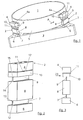
- FIGs 2 to 3 is an enlarged view A first embodiment of a storage device 2 shown.
- the storage device is monolithic or integrally formed with solid joints between the individual moving parts. She has an upper one Mounting part 4, with which the storage device 2 via a pivot point 4a with a socket 5 of the optical element 1 is connected.
- the fastening part 4 also be connected directly to the optical element 1.
- a connecting part 6 On the Bottom or on the side remote from the articulation point 4a Side is the storage facility 2 via a connecting part 6 with connected to the basic structure 3.
- a first bending joint 7 connected in the form of a leaf spring 7, which tangentially to the frame 5 or the optical element 1 is arranged.
- the leaf spring 7 On the side remote from the connecting part 6 Side is the leaf spring 7 with a stiff intermediate member. 8 connected as Ausknicktik, which in turn on the of the Leaf spring 7 opposite side with a further bending member 9, also in the form of a leaf spring connected.
- the leaf spring 9 also extends tangentially with its longitudinal axis to the version 5 or the optical element 1.
- the leaf spring. 9 is on the side remote from the intermediate member 8 side with a Transition plate 10 connected.
- the transition plate 10 is over a in the radial direction - with respect to the optical element - extending bending member 11 as a transverse joint with the fastening part 4 connected.
- leaf spring 7 via a solid-state joint 12 with the connecting part 6 and a solid-state joint 13 connected to the intermediate member 8.
- leaf spring 9 via a solid-state joint 14 with the intermediate member 8 and a solid joint 15 with the transition plate 10 connected.
- the bending member 11 acts due to its small axial extent overall like a solid-state joint 17.
- a larger axial extent possible same for vice versa for the two leaf springs 7 and 9.
- the storage facilities 2 are both individually as well as together by manipulators, not shown axially displaceable, in which case the shift - accordingly the direction of attack - on the responsive leaf springs 7, 9 or the bending member 11 and the solid state joints the optical element 1 is passed.
- manipulators not shown axially displaceable, in which case the shift - accordingly the direction of attack - on the responsive leaf springs 7, 9 or the bending member 11 and the solid state joints the optical element 1 is passed.
- this configuration practically every storage facility 2 is a gimbal Suspension for element 1. Due to the solid state joints but is sufficient rigidity against natural frequencies given.
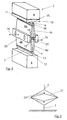
- FIG. 4 shows an embodiment of a bearing device 2 in another embodiment.
- the only difference is that the rigid intermediate member 8 by a parallelogram with the four Pages 8a, 8b, 8c and 8d has been replaced.
- the one-sided located parallelogram pages 8a and 8b are through Solid joints 18 and 19 connected together.
- an actuator member 20 In each case between the solid joints 18 and 19 is an actuator member 20.
- the adjustment movement can be linearized be by optimizing the opening angle ⁇ and ⁇ .
- FIG. 6 is a development of the invention represented, wherein the optical element 1 by three evenly distributed around the circumference arranged manipulators 24 in axial direction is adjustable.
- a sensor device shown with the respective position of the optical element 1 is exactly verifiable.
- FIGS Manipulators 24 on a fixed housing structure 25 of the Optics, e.g. an only partially shown lens 26, from. As can be seen, they act on the housing structure 25 supporting manipulators 24 on the base structure 3 on the Bearing device 2 (in the figure 8 for simplicity only in principle represented) and thus on the optical element 1. Da the basic structure 3 can be made very rigid, e.g. out ceramic material, it can be used to decouple the restoring forces serve the manipulators 24.
- the manipulators 24 are only in principle in the figures 6 to 8 indicated, since this is the most diverse engines or Adjustment devices, the axial length changes according to arrow Generate 27, are used arbitrarily. Thus, e.g. piezoceramic Actuators that change the length of a voltage application experienced, possible.
- the manipulators 24, the on one side with the housing structure 25 and on the other side are connected to the basic structure 3, e.g. each through an opening 28 in the region of the corners of the triangular Basic structure 3 are used from below (see FIG 7).
- the stationary housing structure 25 e.g. three distributed over the circumference arranged sensors 29 are provided.
- the sensors 29 cooperate with counter-members 30 which on the optical element 1 outside the optically effective range are arranged correspondingly opposite.
- the non-contact act As sensor devices, e.g. capacitive sensors or use distance interferometers, the non-contact act.
- the counter-members 30 on the optical element 1 can thereby vapor-deposited as conductive mating surfaces on the optical element 1 be.
Description
Die Erfindung betrifft eine Vorrichtung zur Lagerung eines optischen Elementes in einer Optik, insbesondere eines Spiegels oder einer Linse, in einer Projektionsbelichtungsanlage, insbesondere einem Projektionsobjektiv in der Halbleiter-Lithographie.The invention relates to a device for mounting an optical Element in an optic, in particular a mirror or a lens, in a projection exposure apparatus, in particular a projection objective in semiconductor lithography.
Optische Elemente, wie z.B. Spiegel und Linsen, in der Optik, insbesondere in der Halbleiter-Lithographie, sollen isostatisch und somit deformationsentkoppelt gelagert sein, damit von außen einwirkende Störungen sich möglichst nicht auf das optische Element auswirken. Hierzu ist es bekannt, das optische Element entsprechend "weich" zu lagern. Das Problem bei einer weichen Lagerung besteht jedoch darin, dass man keine ausreichend hohen Eigenfrequenzen erreicht.Optical elements, such as e.g. Mirrors and lenses, in optics, especially in semiconductor lithography, should be isostatic and thus be stored with decoupled decoupling so that external interference should be avoided affect optical element. For this purpose it is known, the optical Store the element according to "soft". The problem with However, a soft storage is that you can not reached sufficiently high natural frequencies.
Die EP 1 209 500 A2 als älteres Recht beschreibt eine Vorrichtung
zur Lagerung eines optischen Elements in einer Baugruppe.
Die Vorrichtung weist wenigstens drei am Umfang des optischen
Elements angeordnete Anbindungsstellen auf. Weiterhin weist
die Vorrichtung Getriebeelemente auf, welche jeweils über eine
radial liegende Biegefeder über einen Kopfpunkt an das optische
Element angebunden ist. Die Getriebeelemente sind dabei
so angeordnet bzw. dimensioniert, dass sie bei Störungseinwirkungen
auf das optische Element einen Kompensationseffekt hinsichtlich
der Deformation der optischen Oberfläche des optischen
Elementes ergeben.
In der DE 199 10 947 A1 ist ebenfalls eine Vorrichtung zur Lagerung bzw. zum Verschieben eines optischen Elementes entlang der optischen Achse offenbart. Das optische Element ist in einem Haltering gelagert, an dem eine Verstelleinrichtung zum Verschieben des optischen Elementes entlang der optischen Achse angreift. Ein Stützring ist über Festkörpergelenke mit dem Haltering verbunden, wobei eine hohe Steifigkeit senkrecht zur optischen Achse erreicht wird. In axialer Richtung weisen die Festkörpergelenke eine ausreichende Weichheit auf. Mittels dieser Vorrichtung können insbesondere große und schwergewichtige optische Elemente sehr präzise in Richtung der optischen Achse verschoben werden, ohne Querbewegungen einzuführen.In DE 199 10 947 A1 is also a device for storage or for moving an optical element along the optical axis revealed. The optical element is in one Retaining ring mounted on which an adjustment for Moving the optical element along the optical axis attacks. A support ring is about solid joints with the Retaining ring connected, with a high rigidity perpendicular to optical axis is achieved. In the axial direction, the Solid joints on a sufficient softness. through This device can be particularly large and heavy optical elements very precise in the direction of the optical Axis be moved without introducing lateral movements.
Der vorliegenden Erfindung liegt daher die Aufgabe zugrunde, eine Vorrichtung zur Lagerung eines optischen Elementes zu schaffen, die einerseits wenig bzw. geringe Kräfte auf das optische Element ausübt, d.h. die sehr gut deformationsentkoppelt ist, wobei jedoch andererseits eine hohe Eigenfrequenz erreicht wird. Insbesondere sollen von außen wirkende Störungen keine Oberflächendeformationen an dem optischen Element bewirken, sondern - falls überhaupt - eine Ganzkörperbewegung.The present invention is therefore based on the object a device for mounting an optical element to create on the one hand little or low forces on the optical Element, i. the very good deformation decoupling is, but on the other hand, a high natural frequency is reached. In particular, external disturbances should act no surface deformations on the optical element cause, if any, a whole body movement.
Erfindungsgemäß wird diese Aufgabe durch die im kennzeichnenden
Teil von Anspruch 1 genannten Merkmale gelöst.According to the invention, this object is achieved by the characterizing
Part of
Mit der erfindungsgemäßen Ausgestaltung lässt sich bei relativ kompakter Bauweise ein steifer Aufbau mit daraus resultierenden hohen Eigenfrequenzen erreichen. Darüber hinaus lässt sich die Lagerung mit wenigen Bauteilen bewerkstelligen, wobei im Bedarfsfalle auch ein monolithisches Design möglich ist.With the embodiment of the invention can be at relative compact design a rigid construction with resulting reach high natural frequencies. In addition, it can be to carry out the storage with few components, in the If necessary, a monolithic design is possible.
Im allgemeinen werden drei über den Umfang verteilt angeordnete Lagereinrichtungen ausreichend sein.In general, three are arranged distributed over the circumference Be sufficient storage facilities.
Erfindungsgemäß weisen die drei Lagereinrichtungen jeweils zwei parallel zur z-Richtung (optische Achse) auf Abstand voneinander angeordnete in tangentialer Richtung verlaufende Biegeglieder mit einem dazwischen angeordneten Zwischenglied auf.According to the invention, the three storage facilities each two parallel to the z-direction (optical axis) at a distance from each other arranged in tangential direction extending bending members with an intermediate member arranged therebetween.
Jede Lagereinrichtung besitzt auf diese Weise z.B. zwei auf Abstand voneinander angeordnete in tangentialer Richtung zu dem optischen Element verlaufende Blattfedern und eine in radialer Richtung verlaufende Blattfeder als Quergelenk. Das zwischen den beiden in tangentialer Richtung verlaufenden Blattfedern angeordnete Zwischenglied kann steif sein oder auch - in einer sehr vorteilhaften und nicht naheliegenden Weiterbildung der Erfindung - als Manipulatoreinrichtung ausgebildet sein. In diesem Falle kann das Zwischenglied mit einer Verstellein-richtung zur Längenänderung parallel zur z-Richtung versehen sein.Each storage device has in this way, e.g. two up Distance apart in the tangential direction the optical element extending leaf springs and one in radial Direction extending leaf spring as a transverse joint. The between the two running in the tangential direction Leaf springs arranged intermediate member may be stiff or also - in a very advantageous and not obvious Further development of the invention - designed as a manipulator device be. In this case, the intermediate member with a Adjustment direction for length change parallel to the z-direction be provided.
Eine mögliche Ausgestaltung hierfür liegt in einem parallelogrammartigen Aufbau bzw. einem Aufbau vergleichbar einem Scheren-Wagenheber-Prinzip. Auf diese Weise lässt sich die Länge des bzw. der über den Umfang verteilt angeordneten Zwischenglieder - mit oder ohne Übersetzung - sehr feinfühlig ändern. Werden alle Zwischenglieder der Lagereinrichtungen gleichmäßig in ihrer Länge verändert, so wird damit das optische Element in z-Richtung verschoben. Bei einzelnen Längenänderungen kann auf diese Weise das optische Element entsprechend gekippt werden.One possible embodiment of this lies in a parallelogram-like Structure or a structure comparable to a scissors jack principle. In this way, the length can be the or the distributed over the circumference arranged intermediate links - with or without translation - very sensitively change. Be all intermediate links of the storage facilities evenly changed in length, so that is the optical element moved in z-direction. For individual changes in length can be tilted in this way, the optical element accordingly.
In einer sehr vorteilhaften Weiterbildung der Erfindung kann vorgesehen sein, dass die äußere Grundstruktur, mit der das optische Element über die Lagereinrichtung verbunden ist, über Manipulatoren mit einer feststehenden Gehäusestruktur der Optik verbunden ist, wobei sich die Manipulatoren an der Gehäusestruktur abstützen. In a very advantageous embodiment of the invention can be provided that the outer basic structure, with which the optical element is connected via the storage device, via Manipulators with a fixed housing structure of the optics connected, wherein the manipulators on the housing structure support.
Erfindungsgemäß wird der Spiegel isostatisch gelagert, wobei durch die Anordnung der Manipulatoren keine negative Veränderung der Eigenfrequenz erreicht wird. Dies bewirkt ihre Wirkungsweise über die äußere Grundstruktur. In die äußere Grundstruktur werden die Momente und Kräfte der Manipulatoren eingeleitet, wodurch sie keine Auswirkungen auf das optische Element haben. Praktisch dient die im allgemeinen sehr steif ausgebildete Grundstruktur zur Entkoppelung der Rückstellkräfte der Manipulatoren.According to the invention, the mirror is stored isostatically, wherein by the arrangement of the manipulators no negative change the natural frequency is reached. This causes their effect over the outer basic structure. In the outer basic structure the moments and forces of the manipulators are initiated, whereby it does not affect the optical element to have. In practical terms, it is generally very stiff Basic structure for decoupling the restoring forces of the Manipulators.
Um eine Ausrichtung bzw. Verstellung des optischen Elementes in axialer Richtung bzw. in Richtung der optischen Achse (z-Achse) zu erreichen, kann man drei gleichmäßig über den Umfang verteilt angeordnete Manipulatoren an der Gehäusestruktur anordnen. Werden die Manipulatoren einzeln betätigt, erreicht man Kippungen um die z-Achse bzw. optische Achse. Werden alle drei Manipulatoren in gleicher Weise betätigt, ergibt sich eine Verschiebung des optischen Elementes in z-Richtung.To an alignment or adjustment of the optical element in axial direction or in the direction of the optical axis (z-axis) You can spread three evenly over the circumference Arrange arranged manipulators on the housing structure. If the manipulators are operated individually, one reaches Tilting about the z-axis or optical axis. Become all three Manipulators operated in the same way, there is a shift of the optical element in the z-direction.
Die Manipulatoren stützen sich an einer feststehenden Gehäusestruktur der Optik ab, die gleichzeitig als Interface-Struktur, z.B. in Ringform, dienen kann.The manipulators are based on a fixed housing structure optics, which at the same time act as an interface structure, e.g. in ring form, can serve.
In einer weiteren vorteilhaften Ausgestaltung der Erfindung kann vorgesehen sein, daß zur Bestimmung der Position des optischen Elementes in der Optik an der Gehäusestruktur Sensoren angeordnet sind, die mit an dem optischen Element angeordneten Gegenglieder zusammenarbeiten.In a further advantageous embodiment of the invention can be provided that for determining the position of the optical Element in the optics on the housing structure sensors are arranged, which are arranged with on the optical element Collaborators work together.
Durch diese Ausgestaltung läßt sich das optische Element in einem Objektiv definiert verstellen bzw. justieren. Hierzu wird die Ist-Position durch die Sensoren erfaßt, wonach eine Soll-Position eingestellt wird.By this configuration, the optical element in Define or adjust a lens defined. For this purpose is the actual position detected by the sensors, after which a desired position is set.
Durch die optionalen Sensoren, welche z.B. drei über den Umfang verteilt angeordnete berührungslose Abstandsmeßsensoren sein können, erfolgt eine direkte und damit genauere Messung, anstelle einer Messung über den Stellweg der Manipulatoren.By the optional sensors, which e.g. three over the Scope distributed arranged non-contact distance sensors be a direct and thus more accurate measurement, instead of a measurement via the travel of the manipulators.
Als Sensoren, wie z.B. berührungslose Abstandsmeßsensoren, können die verschiedensten Sensoren verwendet werden. Hier sind beispielsweise kapazitive Sensoren oder auch ein Abstandsinterferometer möglich, die auf Gegenflächen des optischen Elements wirken. Die Gegenflächen können z.B. hierzu auf das optische Element in einem optisch nicht wirksamen Bereich aufgedampft sein.As sensors, such as Non-contact distance sensors, can the most diverse sensors are used. Here are for example, capacitive sensors or a distance interferometer possible on counter surfaces of the optical element Act. The mating surfaces may e.g. this on the optical Element vapor-deposited in an optically inactive area be.
Vorteilhafte Weiterbildungen und Ausgestaltungen der Erfindung ergeben sich aus den übrigen Unteransprüchen und aus den nachfolgend anhand der Zeichnung prinzipmäßig dargestellten Ausführungsbeispielen.Advantageous developments and refinements of the invention emerge from the remaining dependent claims and from the following Based on the drawing in principle illustrated embodiments.
Es zeigt:
Figur 1- eine perspektivische Darstellung der erfindungsgemäßen Vorrichtung zur Lagerung eines optischen Elementes,
Figur 2- eine Lagereinrichtung in perspektivischer und vergrößerter Darstellung,
Figur 3- eine Seitenansicht der Lagereinrichtung aus Pfeilrichtung
A in der
Figur 1, Figur 4- eine Lagereinrichtung in perspektivischer und vergrößerter Darstellung in einer anderen Ausführungsform,
Figur 5- eine Prinzipdarstellung einer Lagereinrichtung in einer dritten Ausführungsform,
Figur 6- eine perspektivische Ansicht des optischen Elementes mit der Lagereinrichtung und mit Manipulatoren (ohne feststehende Gehäusestruktur) von oben,
Figur 7- eine perspektivische Ansicht der erfindungsgemäßen
Vorrichtung nach der
Figur 6 von unten, und Figur 8- einen Schnitt durch die Vorrichtung nach den
Figuren 6 und 7 mit einer feststehenden Gehäusestruktur zur Abstützung der Manipulatoren und mit einer Sensoreinrichtung.
- FIG. 1
- a perspective view of the device according to the invention for mounting an optical element,
- FIG. 2
- a bearing device in perspective and enlarged representation,
- FIG. 3
- 1 is a side view of the bearing device from the direction of arrow A in FIG. 1,
- FIG. 4
- a bearing device in perspective and enlarged representation in another embodiment,
- FIG. 5
- a schematic diagram of a bearing device in a third embodiment,
- FIG. 6
- a perspective view of the optical element with the storage device and with manipulators (without fixed housing structure) from above,
- FIG. 7
- a perspective view of the device according to the invention according to the figure 6 from below, and
- FIG. 8
- a section through the device according to Figures 6 and 7 with a fixed housing structure for supporting the manipulators and with a sensor device.
Ein optisches Element, z.B. ein Spiegel 1 ist über drei gleichmäßig
über den Umfang verteilt angeordnete Lagereinrichtungen 2
mit einer äußeren Grundstruktur 3 verbunden. Die Grundstruktur
3 kann Teil einer Optik, z.B. eines Projektionsobjektives in
der Halbleiter-Lithographie sein. Die dargestellte dreieckige
Form der Grundstruktur ist lediglich beispielsweise anzusehen.
Im Bedarfsfalle sind hier auch andere Formen, wie z.B. eine
Kreisform möglich.An optical element, e.g. a
Die Lagereinrichtungen 2 sind so aufgebaut, daß sie sehr stark
deformationsentkoppelt sind und dadurch keine von außen über
die Grundstruktur 3 einwirkende Störungen auf das optische Element
1 weitergeben. Die Grundstruktur ist sehr steif ausgeführt
(vorteilhaft ist Keramik), um die von außen kommenden Kräfte
möglichst gut von den Lagerelementen und dem Spiegel zu entkoppeln.
Auf diese Weise wird eine zweifache Deformationsentkoppelung
erreicht. In den Figuren 2 bis 3 ist in vergrößerter Darstellung
eine erste Ausführungsform einer Lagereinrichtung 2
dargestellt. Wie ersichtlich, ist die Lagereinrichtung monolithisch
bzw. einstückig ausgebildet mit Festkörpergelenken
zwischen den einzelnen beweglich Teilen. Sie weist ein oberes
Befestigungsteil 4 auf, mit welchem die Lagereinrichtung 2 über
eine Anlenkstelle 4a mit einer Fassung 5 des optischen Elementes
1 verbunden ist. Gegebenenfalls kann das Befestigungsteil 4
auch direkt mit dem optischen Element 1 verbunden sein. Auf der
Unterseite bzw. auf der von der Anlenkstelle 4a abgewandten
Seite ist die Lagereinrichtung 2 über ein Verbindungsteil 6 mit
der Grundstruktur 3 verbunden. Mit den Verbindungsteil 6 ist
ein erstes Biegegelenk 7 in Form einer Blattfeder 7 verbunden,
welches tangential zur Fassung 5 bzw. dem optischen Element 1
angeordnet ist. Auf der von dem Verbindungsteil 6 abgewandten
Seite ist die Blattfeder 7 mit einem steifen Zwischenglied 8
als Ausknickschutz verbunden, welches wiederum auf der von der
Blattfeder 7 abgewandten Seite mit einem weiteren Biegeglied 9,
ebenfalls in Form einer Blattfeder, verbunden ist. Die Blattfeder
9 erstreckt sich ebenfalls mit ihrer Längsachse tangential
zu der Fassung 5 bzw. dem optischen Element 1. Die Blattfeder 9
ist auf der von dem Zwischenglied 8 abgewandten Seite mit einer
Übergangsplatte 10 verbunden. Die Übergangsplatte 10 ist über
ein in radialer Richtung - bezogen auf das optische Element -
verlaufendes Biegeglied 11 als Quergelenk mit dem Befestigungsteil
4 verbunden.The
Wie ersichtlich, ist damit die Blattfeder 7 über ein Festkörpergelenk
12 mit dem Verbindungsteil 6 und über ein Festkörpergelenk
13 mit dem Zwischenglied 8 verbunden. In gleicher Weise
ist die Blattfeder 9 über ein Festkörpergelenk 14 mit dem Zwischenglied
8 und über ein Festkörpergelenk 15 mit der Übergangsplatte
10 verbunden. Das Biegeglied 11 wirkt aufgrund seiner
geringen axialen Erstreckung insgesamt wie ein Festkörpergelenk
17. Selbstverständlich ist im Rahmen der Erfindung auch
hier eine größere axiale Erstreckung möglich. Gleiches gilt
umgekehrt für die beiden Blattfedern 7 und 9.As can be seen, so is the
Im Bedarfsfalle sind die Lagereinrichtungen 2 sowohl einzeln
als auch gemeinsam durch nicht näher dargestellte Manipulatoren
axial verschiebbar, wobei dann die Verschiebung - entsprechend
der Angriffsrichtung - über die darauf ansprechenden Blattfedern
7, 9 oder dem Biegeglied 11 bzw. die Festkörpergelenke auf
das optische Element 1 weitergegeben wird. Mit dieser Ausgestaltung
stellt praktisch jede Lagereinrichtung 2 eine kardanische
Aufhängung für das Element 1 dar. Aufgrund der Festkörpergelenke
ist jedoch eine ausreichende Steifigkeit gegen Eigenfrequenzen
gegeben.If necessary, the
Die Figur 4 zeigt eine Ausgestaltung einer Lagereinrichtung 2
in einer anderen Ausgestaltung. Grundsätzlich ist der Aufbau
identisch mit der Lagereinrichtung nach den Figuren 1 bis 3,
weshalb für die gleichen Teile auch die gleichen Bezugszeichen
beibehalten worden sind. Unterschiedlich ist lediglich, daß das
steife Zwischenglied 8 durch ein Parallelogramm mit den vier
Seiten 8a, 8b, 8c und 8d ersetzt worden ist. Die auf einer Seite
sich befindenden Parallelogrammseiten 8a und 8b sind durch
Festkörpergelenke 18 und 19 miteinander verbunden. Gleiches
gilt für die Parallelogrammseiten 8c und 8d, die sich auf der
anderen Seite befinden. Jeweils zwischen den Festkörpergelenken
18 und 19 befindet sich ein Aktuatorglied 20. Werden durch eine
nicht näher dargestellte Betätigungseinrichtung Kräfte in
Pfeilrichtung 16 auf die Aktuatorglieder 20 ausgeübt, so verändert
sich der Öffnungswinkel α des Parallelogrammes. Je nach
Öffnungswinkel α ergibt sich eine entsprechende Über- oder Untersetzung
des Verschiebeweges, welcher sich bezüglich des optischen
Elementes 1 in einer Höhenänderung in z-Richtung
(optische Achse) auswirkt. Bei kleinem Öffnungswinkel α wird
eine entsprechend starke Untersetzung erreicht, bei einem Öffnungswinkel
von 45° ist das Übersetzungsverhältnis 1 : 1 und
bei größerem Öffnungswinkel α das Übersetzungsverhältnis entsprechend
größer.FIG. 4 shows an embodiment of a
Da man im allgemeinen eine sehr feinfühlige Verstellung in z-Richtung
erreichen möchte, kann es von Vorteil sein, wenn man
eine nochmalige Untersetzung durch ein zweites Parallelogramm
21 mit entsprechend vier Parallelogrammseiten vornimmt, welches
sich im Inneren des Parallelogrammes mit den Seiten 8a bis 8d
befindet (siehe Figur 5). Verschiebekräfte gemäß Pfeilrichtung
22 auf das innere Parallelogramm 21 wirken sich entsprechend
untersetzt auf das äußere Parallelogramm mit den Seiten 8a bis
8d aus. Dabei wirken die Verschiebekräfte 22 jeweils seitlich
zwischen den Parallelogrammseiten 8a und 8b bzw. 8c und 8d und
verändern dadurch den Öffnungswinkel α sehr feinfühlig.Since you are in general a very sensitive adjustment in the z direction
It may be beneficial if you want to achieve that
a second reduction by a
Durch das zweite Parallelogramm kann die Justagebewegung linearisiert werden und zwar durch Optimieren der Öffnungswinkel α und β. By the second parallelogram the adjustment movement can be linearized be by optimizing the opening angle α and β.
In den Figuren 6 bis 8 ist eine Weiterbildung der Erfindung
dargestellt, wobei das optische Element 1 durch drei gleichmäßig
über den Umfang verteilt angeordnete Manipulatoren 24 in
axialer Richtung verstellbar ist. Zusätzlich ist in der Figur 8
eine Sensoreinrichtung dargestellt, mit der die jeweilige Position
des optischen Elementes 1 exakt überprüfbar ist.In Figures 6 to 8 is a development of the invention
represented, wherein the
Wie aus der Figur 8 weiterhin ersichtlich ist, stützen sich die
Manipulatoren 24 auf einer feststehenden Gehäusestruktur 25 der
Optik, z.B. eines nur teilweise dargestellten Objektives 26,
ab. Wie ersichtlich, wirken die sich auf der Gehäusestruktur 25
abstützenden Manipulatoren 24 über die Grundstruktur 3 auf die
Lagereinrichtung 2 (in der Figur 8 zur Vereinfachung nur prinzipmäßig
dargestellt) und damit auf das optische Element 1. Da
die Grundstruktur 3 sich sehr steif ausbilden läßt, z.B. aus
keramischem Material, kann sie zur Entkoppelung der Rückstellkräfte
der Manipulatoren 24 dienen.As can also be seen from FIG. 8, the
Die Manipulatoren 24 sind in den Figuren 6 bis 8 nur prinzipmäßig
angedeutet, da hierfür die verschiedensten Motoren bzw.
Verstelleinrichtungen, die axiale Längenänderungen gemäß Pfeil
27 erzeugen, beliebig einsetzbar sind. So sind z.B. piezokeramische
Aktuatoren, die bei einer Spannungsbeaufschlagung Längenänderungen
erfahren, möglich. Die Manipulatoren 24, die auf
einer Seite mit der Gehäusestruktur 25 und auf der anderen Seite
mit der Grundstruktur 3 verbunden sind, können z.B. jeweils
durch eine Öffnung 28 im Bereich der Ecken der dreieckförmigen
Grundstruktur 3 von unten her eingesetzt werden (siehe Figur
7).The
Um die Ist-Position des optischen Elementes 1 zu erfassen und
dann entsprechend eine Soll-Position möglichst exakt einstellen
zu können nach einer entsprechenden Betätigung der Manipulatoren
24, sind an der feststehenden Gehäusestruktur 25 z.B. drei
über den Umfang verteilt angeordnete Sensoren 29 vorgesehen.
Hierzu kann z.B. die Gehäusestruktur 25, welche auch als Interfacering
dienen kann, mit einer nach innen gerichteten Erweiterung
25' (nur gestrichelt dargestellt) versehen sein, in oder
an der dann die Sensoren 29 gelagert sind.To detect the actual position of the
Die Sensoren 29 arbeiten mit Gegenglieder 30 zusammen, die an
dem optischen Element 1 außerhalb des optisch wirksamen Bereiches
entsprechend gegenüberliegend angeordnet sind.The
Als Sensoreinrichtungen lassen sich z.B. kapazitive Sensoren
oder auch Abstandsinterferometer verwenden, die berührungslos
agieren. Die Gegenglieder 30 an dem optischen Element 1 können
dabei als leitende Gegenflächen auf das optische Element 1 aufgedampft
sein.As sensor devices, e.g. capacitive sensors
or use distance interferometers, the non-contact
act. The counter-members 30 on the
Claims (18)
- Device for mounting an optical element (1), particularly a mirror or a lens, in an optical system of a projection exposure apparatus, in particular a projection objective in semiconductor lithography, having at least three guide locations (4a) arranged on the circumference of the optical element (1), and on each of these a mounting unit (2) with at least one leafspring-like flexion member, which is connected on the other side from the guide location (4a) to an outer base structure (3), characterised in that the mounting unit (2) has two leafspring-like flexion members (7, 9) arranged parallel to the optical axis at a distance from each other and extending in a direction tangential to the optical element (1), with an intermediate member (8) arranged between them, and at least one leafspring-like connecting member (11) arranged in a direction radial to the optical element.
- Device according to Claim 1, characterised in that the flexion members (7, 9, 11) are respectively connected via solid-state articulations (12, 13, 14, 15, 17) to the parts lying next to them, such as a guide location (4a), connecting parts (6), an intermediate member (8), a junction plate (10).
- Device according to Claim 1, characterised in that the intermediate member (8) is provided with an adjustment unit (16) for changing the length of the intermediate member (8) parallel to the optical axis.
- Device according to Claim 3, characterised in that the adjustment unit has at least one parallelogram-like shape (8a, 8b, 8c, 8d) whose aperture angle (α) can be adjusted by the adjustment unit (16).
- Device according to Claim 4, characterised in that the parallelogram-like sides (8a, 8b, 8c, 8d) are respectively connected together via solid-state articulations (12, 13, 14, 15, 17).
- Device according to Claim 5, characterised in that an actuator member (20) respectively engages between the parallelogram sides (8a, 8b and 8c, 8d) located on one side.
- Device according to Claim 4, characterised in that a further parallelogram (21) is arranged inside the parallelogram (8a, 8b, 8c, 8d) and is provided with an adjustment unit (22) which respectively engages between the parallelogram sides (8a, 8b and 8c, 8d) on each side in order to change the aperture angle (α).
- Device according to one of Claims 1 to 7, characterised in that the adjustment units (16, 20) of the mounting units (2) arranged distributed over the circumference can respectively be adjusted individually or together.
- Device according to one of Claims 1 to 8, characterised in that three mounting units (2) are provided, arranged distributed over the circumference.
- Device according to one of Claims 1 to 9, characterised in that the mounting units (2) are monolithically designed.
- Device according to one of Claims 1 to 10, characterised in that the base structure (3), on which the mounting unit (2) is supported, is designed as a rigid structure, in particular a ceramic structure.
- Device according to Claim 1, characterised in that the outer base unit (3), to which the optical element (1) is connected via the mounting unit (2), is connected via manipulators (24) to a static housing structure (25) of the optical system (26), the manipulators (24) being supported on the housing structure (25).
- Device according to Claim 12, characterised in that the manipulators (24) are intended for adjustment of the base structure (3) in the axial direction.
- Device according to Claim 13, characterised in that three manipulators (24), distributed uniformly over the circumference, are arranged on the housing structure (25).
- Device according to Claim 12, characterised in that sensors (29), which interact with backing members (30) arranged on the optical element (1), are arranged on the housing structure (25) in order to determine the position of the optical element (1) in the optical system (26).
- Device according to Claim 15, characterised in that the sensors (29) are designed as contactless distance measurement sensors arranged distributed over the circumference of the housing structure (25), or as distance interferometers.
- Device according to Claim 15 and 16, characterised in that the backing members (30) are designed as backing surfaces, which are arranged outside the optically active region on the optical element (1).
- Device according to Claim 17, characterised in that in the case of capacitive sensors (29) or in the case of distance interferometers (29), the backing surfaces (30) are vapour deposited on the optical element (1).
Applications Claiming Priority (2)
| Application Number | Priority Date | Filing Date | Title |
|---|---|---|---|
| DE10115914 | 2001-03-30 | ||
| DE10115914A DE10115914A1 (en) | 2001-03-30 | 2001-03-30 | Device for storing an optical element in an optical system |
Publications (3)
| Publication Number | Publication Date |
|---|---|
| EP1245982A2 EP1245982A2 (en) | 2002-10-02 |
| EP1245982A3 EP1245982A3 (en) | 2003-08-27 |
| EP1245982B1 true EP1245982B1 (en) | 2005-11-30 |
Family
ID=7679768
Family Applications (1)
| Application Number | Title | Priority Date | Filing Date |
|---|---|---|---|
| EP02005695A Expired - Lifetime EP1245982B1 (en) | 2001-03-30 | 2002-03-13 | Apparatus for holding an optical element in an optical device |
Country Status (5)
| Country | Link |
|---|---|
| US (1) | US6870632B2 (en) |
| EP (1) | EP1245982B1 (en) |
| JP (1) | JP2002350699A (en) |
| DE (2) | DE10115914A1 (en) |
| TW (1) | TW548525B (en) |
Families Citing this family (59)
| Publication number | Priority date | Publication date | Assignee | Title |
|---|---|---|---|---|
| US20060126195A1 (en) * | 2002-08-08 | 2006-06-15 | Johannes Rau | Device for receiving an optical module in an imaging unit |
| DE10246828A1 (en) * | 2002-10-08 | 2004-04-22 | Carl Zeiss Smt Ag | Objective, in particular projection objective for microlithography used in the manufacture of semiconductor components has one housing for optical elements provided with mating surfaces |
| AU2003219097A1 (en) * | 2003-03-26 | 2004-10-18 | Carl Zeiss Smt Ag | Device for the low-deformation replaceable mounting of an optical element |
| US7760452B2 (en) * | 2003-04-25 | 2010-07-20 | Canon Kabushiki Kaisha | Driving apparatus, optical system, exposure apparatus and device fabrication method |
| JP2004343101A (en) * | 2003-04-25 | 2004-12-02 | Canon Inc | Drive mechanism, exposure apparatus having it, and device manufacturing method |
| AU2003254364A1 (en) * | 2003-07-17 | 2005-03-07 | Carl Zeiss Smt Ag | Device for mounting an optical element, particularly a lens in an objective |
| DE10344178B4 (en) * | 2003-09-24 | 2006-08-10 | Carl Zeiss Smt Ag | Holding and positioning device for an optical element |
| US7448763B2 (en) * | 2003-10-02 | 2008-11-11 | Carl Zeiss Smt Ag | Optical subassembly and projection objective in semiconductor lithography |
| DE10350574A1 (en) * | 2003-10-30 | 2005-06-02 | Carl Zeiss Jena Gmbh | Solid joint guides |
| DE10352820A1 (en) * | 2003-11-12 | 2005-06-23 | Carl Zeiss Smt Ag | Flange assembly of an optical system |
| JP2005166785A (en) * | 2003-12-01 | 2005-06-23 | Canon Inc | Device and method for detecting position and aligner |
| US7265917B2 (en) | 2003-12-23 | 2007-09-04 | Carl Zeiss Smt Ag | Replacement apparatus for an optical element |
| KR101122881B1 (en) * | 2004-02-20 | 2012-03-20 | 칼 짜이스 에스엠테 게엠베하 | Projection lens of a microlithographic projection exposure system |
| US7581305B2 (en) | 2004-04-12 | 2009-09-01 | Carl Zeiss Smt Ag | Method of manufacturing an optical component |
| DE102004018656A1 (en) * | 2004-04-13 | 2005-11-03 | Carl Zeiss Smt Ag | Optical element |
| US7604359B2 (en) | 2004-05-04 | 2009-10-20 | Carl Zeiss Smt Ag | High positioning reproducible low torque mirror-actuator interface |
| DE102004024755B4 (en) * | 2004-05-12 | 2006-02-23 | Fraunhofer-Gesellschaft zur Förderung der angewandten Forschung e.V. | Holder for optical elements |
| WO2006000352A1 (en) | 2004-06-29 | 2006-01-05 | Carl Zeiss Smt Ag | Positioning unit and alignment device for an optical element |
| WO2007017013A2 (en) * | 2005-07-01 | 2007-02-15 | Carl Zeiss Smt Ag | Arrangement for mounting an optical component |
| TWI372271B (en) * | 2005-09-13 | 2012-09-11 | Zeiss Carl Smt Gmbh | Optical element unit, optical element holder, method of manufacturing an optical element holder, optical element module, optical exposure apparatus, and method of manufacturing a semiconductor device |
| DE102005049731A1 (en) * | 2005-10-14 | 2007-04-19 | Cube Optics Ag | Optical structure with elastic suspension and method for producing such |
| US8441747B2 (en) | 2006-09-14 | 2013-05-14 | Carl Zeiss Smt Gmbh | Optical module with minimized overrun of the optical element |
| JP5043468B2 (en) * | 2007-02-23 | 2012-10-10 | キヤノン株式会社 | Holding device |
| JP5013906B2 (en) * | 2007-03-05 | 2012-08-29 | キヤノン株式会社 | Optical element holding device |
| DE102008040218A1 (en) | 2007-07-11 | 2009-01-15 | Carl Zeiss Smt Ag | Optical device e.g. illumination system, operating method for use in projection exposure system, involves storing element such that no parasitic adjustments or changes of element develop during or after rotation in imaging characteristics |
| WO2009024192A1 (en) | 2007-08-23 | 2009-02-26 | Carl Zeiss Smt Ag | Optical element module with minimized parasitic loads |
| US20090219497A1 (en) * | 2008-02-28 | 2009-09-03 | Carl Zeiss Smt Ag | Optical device with stiff housing |
| JP5127515B2 (en) * | 2008-03-12 | 2013-01-23 | キヤノン株式会社 | Optical element holding device |
| DE102008000967B4 (en) | 2008-04-03 | 2015-04-09 | Carl Zeiss Smt Gmbh | Projection exposure machine for EUV microlithography |
| DE102008026979B3 (en) * | 2008-05-29 | 2009-12-24 | Carl Zeiss Ag | Device for correcting image defect in optical system, has multiple optical components, which are arranged along common axis, where unit is provided for adjusting position of optical element |
| DE102008036574A1 (en) | 2008-07-31 | 2010-02-04 | Carl Zeiss Laser Optics Gmbh | Optical element i.e. mirror, supporting device for fusion of silicon layer on substrate, has elastic units formed as monopods, and optical element and area elongated in square-shaped manner with preset aspect ratio |
| US8305701B2 (en) * | 2008-09-17 | 2012-11-06 | Carl Zeiss Smt Gmbh | Connecting arrangement for an optical device |
| DE102009044957A1 (en) * | 2008-09-30 | 2010-04-08 | Carl Zeiss Smt Ag | Support elements for an optical element |
| DE102009045163B4 (en) * | 2009-09-30 | 2017-04-06 | Carl Zeiss Smt Gmbh | Optical arrangement in a microlithographic projection exposure apparatus |
| DE102010005993B4 (en) | 2010-01-27 | 2016-10-20 | Deutsches Zentrum für Luft- und Raumfahrt e.V. | Laser scanner device and method for three-dimensional non-contact environmental detection with a laser scanner device |
| DE102010018224A1 (en) * | 2010-04-23 | 2012-02-16 | Carl Zeiss Smt Gmbh | Optical module with an adjustable optical element |
| US8651677B2 (en) * | 2010-06-28 | 2014-02-18 | Lexmark International, Inc. | Mounting mechanism for a component of an imaging apparatus, and methods of making and using same |
| US8542450B2 (en) | 2011-02-08 | 2013-09-24 | Utah State University Research Foundation | Kinematic optic mount |
| JP5306393B2 (en) * | 2011-03-04 | 2013-10-02 | 三菱電機株式会社 | Mirror support mechanism |
| DE102011075316A1 (en) * | 2011-05-05 | 2012-11-08 | Carl Zeiss Smt Gmbh | Optical module with a measuring device |
| DE102012102566B4 (en) | 2012-03-26 | 2019-02-21 | Trumpf Werkzeugmaschinen Gmbh + Co. Kg | Transmission element for an adjusting movement of an optical element, positioning and machining head for a laser processing machine |
| DE102012209309A1 (en) * | 2012-06-01 | 2013-12-05 | Carl Zeiss Smt Gmbh | Lithographic apparatus and method for producing a mirror assembly |
| KR102001460B1 (en) | 2013-03-18 | 2019-07-19 | 삼성디스플레이 주식회사 | Optical module for laser beam shaking |
| CN104076612B (en) * | 2013-03-27 | 2016-04-20 | 上海微电子装备有限公司 | Heavy load flexible supporting device |
| DE102013109185B3 (en) * | 2013-08-23 | 2014-05-22 | Jenoptik Optical Systems Gmbh | Thermal compensated optical component forms spacing between first and third solid joints, and second and fourth solid joints, where spacing is equal to twice length of one coupling of connection unit |
| CN104459937B (en) * | 2013-09-12 | 2018-01-19 | 上海微电子装备(集团)股份有限公司 | A kind of speculum precision adjustment unit |
| CN104391367B (en) * | 2014-10-15 | 2017-02-15 | 中国科学院光电研究院 | Four-dimensional adjustment apparatus of extreme ultraviolet reflecting lens |
| DE102015223520A1 (en) * | 2015-11-27 | 2016-10-20 | Carl Zeiss Smt Gmbh | Projection exposure apparatus for semiconductor lithography |
| CN105467548B (en) * | 2015-12-04 | 2018-05-01 | 中国科学院长春光学精密机械与物理研究所 | The replaceable lithographic objective frame of the eyeglass of high position precision |
| CN105607211B (en) * | 2015-12-31 | 2018-06-19 | 中国华录集团有限公司 | Lens adjust structure and projection optical system |
| WO2017207016A1 (en) * | 2016-05-30 | 2017-12-07 | Carl Zeiss Smt Gmbh | Optical imaging arrangement with a piezoelectric device |
| DE102016217479A1 (en) * | 2016-09-14 | 2017-09-14 | Carl Zeiss Smt Gmbh | OPTICAL MODULE WITH TILTABLE OPTICAL SURFACES |
| CN106405787B (en) * | 2016-12-10 | 2020-08-21 | 中国科学院长春光学精密机械与物理研究所 | Angle adjusting device for reflector optical element |
| DE102017115050B3 (en) * | 2017-07-05 | 2018-03-29 | Physik Instrumente (Pi) Gmbh & Co. Kg | joint |
| US11086100B2 (en) | 2017-12-14 | 2021-08-10 | Mitsubishi Electric Corporation | Mirror support and mirror support mechanism |
| DE102018107034A1 (en) * | 2018-03-23 | 2019-09-26 | Huber+Suhner Cube Optics Ag | Elastic suspension for optical design |
| JP7118024B2 (en) * | 2019-03-26 | 2022-08-15 | 三菱電機株式会社 | Reducer and structure |
| CN110412714B (en) * | 2019-06-27 | 2022-02-01 | 北京空间机电研究所 | Large-diameter reflector supporting mechanism |
| EP4286912A1 (en) * | 2021-01-29 | 2023-12-06 | Mitsubishi Electric Corporation | Mirror support mechanism and optical device |
Family Cites Families (15)
| Publication number | Priority date | Publication date | Assignee | Title |
|---|---|---|---|---|
| CH371906A (en) * | 1958-08-11 | 1963-09-15 | Optische Ind De Oude Delft Nv | Holder for optical elements |
| JPS5790607A (en) | 1980-11-28 | 1982-06-05 | Fujitsu Ltd | Optical glass fitting device |
| DD215407A1 (en) * | 1983-04-04 | 1984-11-07 | Zeiss Jena Veb Carl | RINGFUL LENS MOUNTING FOR OPTICAL SYSTEMS HIGH PERFORMANCE |
| US4969726A (en) | 1985-06-03 | 1990-11-13 | Northrop Corporation | Ring laser gyro path-length-control mechanism |
| US4733945A (en) | 1986-01-15 | 1988-03-29 | The Perkin-Elmer Corporation | Precision lens mounting |
| DE3740515A1 (en) | 1987-11-30 | 1989-06-08 | Diehl Gmbh & Co | Adjusting device for a deformable mirror |
| DE69133142T2 (en) | 1990-08-15 | 2003-07-24 | Mitsubishi Electric Corp | Passive temperature compensation reflector |
| US5428482A (en) * | 1991-11-04 | 1995-06-27 | General Signal Corporation | Decoupled mount for optical element and stacked annuli assembly |
| DE4236355C2 (en) | 1992-10-28 | 2001-11-08 | Zeiss Carl | Adaptive membrane mirror |
| DE19825716A1 (en) | 1998-06-09 | 1999-12-16 | Zeiss Carl Fa | Optical element and socket assembly |
| FR2783055B1 (en) * | 1998-09-04 | 2000-11-24 | Essilor Int | SUPPORT FOR OPTICAL LENS, AND METHOD FOR IMPLEMENTING SAME |
| DE19904152A1 (en) * | 1999-02-03 | 2000-08-10 | Zeiss Carl Fa | Assembly of an optical element and a socket |
| DE19910947A1 (en) * | 1999-03-12 | 2000-09-14 | Zeiss Carl Fa | Device for moving an optical element along the optical axis |
| JP4482990B2 (en) * | 1999-12-10 | 2010-06-16 | 株式会社ニコン | Lens holding frame and lens barrel |
| DE10053899A1 (en) * | 2000-10-31 | 2002-05-08 | Zeiss Carl | Bearing system for precision optical system minimises distortion from dynamic forces |
-
2001
- 2001-03-30 DE DE10115914A patent/DE10115914A1/en not_active Withdrawn
-
2002
- 2002-03-13 DE DE50205077T patent/DE50205077D1/en not_active Expired - Fee Related
- 2002-03-13 EP EP02005695A patent/EP1245982B1/en not_active Expired - Lifetime
- 2002-03-27 US US10/108,878 patent/US6870632B2/en not_active Expired - Fee Related
- 2002-03-29 TW TW091106342A patent/TW548525B/en not_active IP Right Cessation
- 2002-04-01 JP JP2002098814A patent/JP2002350699A/en not_active Ceased
Also Published As
| Publication number | Publication date |
|---|---|
| DE10115914A1 (en) | 2002-10-02 |
| TW548525B (en) | 2003-08-21 |
| EP1245982A3 (en) | 2003-08-27 |
| JP2002350699A (en) | 2002-12-04 |
| EP1245982A2 (en) | 2002-10-02 |
| US20020176094A1 (en) | 2002-11-28 |
| US6870632B2 (en) | 2005-03-22 |
| DE50205077D1 (en) | 2006-01-05 |
Similar Documents
| Publication | Publication Date | Title |
|---|---|---|
| EP1245982B1 (en) | Apparatus for holding an optical element in an optical device | |
| EP1275995B1 (en) | Exposure lens with a plurality of optical elements | |
| EP1015931B1 (en) | Projection light facility for microlithography | |
| EP2153185B1 (en) | Adjustable parallel guide for compact gravimetric measuring instruments | |
| EP1113191B1 (en) | Motion transmitting device | |
| EP1209500B1 (en) | Arrangement for mounting an optical element | |
| DE10344178B4 (en) | Holding and positioning device for an optical element | |
| EP1028342B1 (en) | Device for pivoting an optical element around two orthogonal axes | |
| DE19910947A1 (en) | Device for moving an optical element along the optical axis | |
| WO2008022797A1 (en) | Projection exposure apparatus and optical system | |
| EP1577693A2 (en) | Objective comprising at least one optical element | |
| DE102015115718A1 (en) | measurement device | |
| EP2302432B1 (en) | Device for temperature-dependent axial movement of optical components | |
| EP2679962B1 (en) | Position measuring device | |
| EP0469412A1 (en) | Flexural pivot for the hinged connection of two pieces | |
| EP0943947A2 (en) | Active mirror. | |
| DE212005000064U1 (en) | Device for moving components, in particular in optical systems | |
| DE2236529B2 (en) | Rotating device of high accuracy for optical devices, in particular electron microscopes | |
| EP0431114A1 (en) | Fixed gantry mount for a precision coordinate-measuring instrument. | |
| DE102018200181A1 (en) | Projection exposure machine with reduced parasitic deformation of components | |
| EP2802922A1 (en) | Image-stabilized binocular long-range device | |
| DE102004052154A1 (en) | Rotation bearing for angle positioning of e.g. optical mirror, has retaining unit, solid body joints, support couplers and base unit forming closed bearing cage, where couplers are designed as cage supports and distributed at circumference | |
| DE10250094B4 (en) | Measuring system with a coupling rod | |
| DE102007013916B4 (en) | Contour measuring device | |
| DE102022115934B3 (en) | Screw gear drive as well as reticle stage and measuring device for semiconductor lithography applications |
Legal Events
| Date | Code | Title | Description |
|---|---|---|---|
| PUAI | Public reference made under article 153(3) epc to a published international application that has entered the european phase |
Free format text: ORIGINAL CODE: 0009012 |
|
| AK | Designated contracting states |
Kind code of ref document: A2 Designated state(s): AT BE CH CY DE DK ES FI FR GB GR IE IT LI LU MC NL PT SE TR |
|
| AX | Request for extension of the european patent |
Free format text: AL;LT;LV;MK;RO;SI |
|
| PUAL | Search report despatched |
Free format text: ORIGINAL CODE: 0009013 |
|
| AK | Designated contracting states |
Designated state(s): AT BE CH CY DE DK ES FI FR GB GR IE IT LI LU MC NL PT SE TR |
|
| AX | Request for extension of the european patent |
Extension state: AL LT LV MK RO SI |
|
| 17P | Request for examination filed |
Effective date: 20031119 |
|
| 17Q | First examination report despatched |
Effective date: 20040216 |
|
| AKX | Designation fees paid |
Designated state(s): DE FR GB NL |
|
| RAP1 | Party data changed (applicant data changed or rights of an application transferred) |
Owner name: CARL ZEISS SMT AG |
|
| GRAP | Despatch of communication of intention to grant a patent |
Free format text: ORIGINAL CODE: EPIDOSNIGR1 |
|
| GRAS | Grant fee paid |
Free format text: ORIGINAL CODE: EPIDOSNIGR3 |
|
| GRAA | (expected) grant |
Free format text: ORIGINAL CODE: 0009210 |
|
| AK | Designated contracting states |
Kind code of ref document: B1 Designated state(s): DE FR GB NL |
|
| PG25 | Lapsed in a contracting state [announced via postgrant information from national office to epo] |
Ref country code: GB Free format text: LAPSE BECAUSE OF FAILURE TO SUBMIT A TRANSLATION OF THE DESCRIPTION OR TO PAY THE FEE WITHIN THE PRESCRIBED TIME-LIMIT Effective date: 20051130 Ref country code: NL Free format text: LAPSE BECAUSE OF FAILURE TO SUBMIT A TRANSLATION OF THE DESCRIPTION OR TO PAY THE FEE WITHIN THE PRESCRIBED TIME-LIMIT Effective date: 20051130 |
|
| REG | Reference to a national code |
Ref country code: GB Ref legal event code: FG4D Free format text: NOT ENGLISH |
|
| REF | Corresponds to: |
Ref document number: 50205077 Country of ref document: DE Date of ref document: 20060105 Kind code of ref document: P |
|
| NLV1 | Nl: lapsed or annulled due to failure to fulfill the requirements of art. 29p and 29m of the patents act | ||
| GBV | Gb: ep patent (uk) treated as always having been void in accordance with gb section 77(7)/1977 [no translation filed] |
Effective date: 20051130 |
|
| PLBE | No opposition filed within time limit |
Free format text: ORIGINAL CODE: 0009261 |
|
| STAA | Information on the status of an ep patent application or granted ep patent |
Free format text: STATUS: NO OPPOSITION FILED WITHIN TIME LIMIT |
|
| 26N | No opposition filed |
Effective date: 20060831 |
|
| EN | Fr: translation not filed | ||
| PG25 | Lapsed in a contracting state [announced via postgrant information from national office to epo] |
Ref country code: FR Free format text: LAPSE BECAUSE OF FAILURE TO SUBMIT A TRANSLATION OF THE DESCRIPTION OR TO PAY THE FEE WITHIN THE PRESCRIBED TIME-LIMIT Effective date: 20070119 |
|
| PGFP | Annual fee paid to national office [announced via postgrant information from national office to epo] |
Ref country code: DE Payment date: 20080321 Year of fee payment: 7 |
|
| PG25 | Lapsed in a contracting state [announced via postgrant information from national office to epo] |
Ref country code: FR Free format text: LAPSE BECAUSE OF FAILURE TO SUBMIT A TRANSLATION OF THE DESCRIPTION OR TO PAY THE FEE WITHIN THE PRESCRIBED TIME-LIMIT Effective date: 20060331 |
|
| PG25 | Lapsed in a contracting state [announced via postgrant information from national office to epo] |
Ref country code: FR Free format text: LAPSE BECAUSE OF FAILURE TO SUBMIT A TRANSLATION OF THE DESCRIPTION OR TO PAY THE FEE WITHIN THE PRESCRIBED TIME-LIMIT Effective date: 20051130 |
|
| PG25 | Lapsed in a contracting state [announced via postgrant information from national office to epo] |
Ref country code: DE Free format text: LAPSE BECAUSE OF NON-PAYMENT OF DUE FEES Effective date: 20091001 |