EP1245873A2 - Dichtring - Google Patents
Dichtring Download PDFInfo
- Publication number
- EP1245873A2 EP1245873A2 EP02006463A EP02006463A EP1245873A2 EP 1245873 A2 EP1245873 A2 EP 1245873A2 EP 02006463 A EP02006463 A EP 02006463A EP 02006463 A EP02006463 A EP 02006463A EP 1245873 A2 EP1245873 A2 EP 1245873A2
- Authority
- EP
- European Patent Office
- Prior art keywords
- sealing
- sealing ring
- seal
- sealing sleeve
- ring according
- Prior art date
- Legal status (The legal status is an assumption and is not a legal conclusion. Google has not performed a legal analysis and makes no representation as to the accuracy of the status listed.)
- Granted
Links
- 238000007789 sealing Methods 0.000 title claims abstract description 177
- 239000004810 polytetrafluoroethylene Substances 0.000 claims abstract description 9
- 229920001343 polytetrafluoroethylene Polymers 0.000 claims abstract description 9
- 239000000463 material Substances 0.000 claims description 18
- 150000001875 compounds Chemical class 0.000 claims description 3
- 239000002861 polymer material Substances 0.000 abstract description 2
- 238000009792 diffusion process Methods 0.000 description 6
- 238000004519 manufacturing process Methods 0.000 description 3
- 239000000853 adhesive Substances 0.000 description 2
- 230000001070 adhesive effect Effects 0.000 description 2
- 239000011248 coating agent Substances 0.000 description 2
- 238000000576 coating method Methods 0.000 description 2
- 230000017525 heat dissipation Effects 0.000 description 2
- 238000005461 lubrication Methods 0.000 description 2
- 239000003566 sealing material Substances 0.000 description 2
- 230000002411 adverse Effects 0.000 description 1
- 239000002131 composite material Substances 0.000 description 1
- 229920001971 elastomer Polymers 0.000 description 1
- 239000000806 elastomer Substances 0.000 description 1
- 239000013536 elastomeric material Substances 0.000 description 1
- 239000002184 metal Substances 0.000 description 1
- 239000011148 porous material Substances 0.000 description 1
- 230000036316 preload Effects 0.000 description 1
- 239000000565 sealant Substances 0.000 description 1
- 239000012815 thermoplastic material Substances 0.000 description 1
- 230000001052 transient effect Effects 0.000 description 1
Images


Classifications
-
- F—MECHANICAL ENGINEERING; LIGHTING; HEATING; WEAPONS; BLASTING
- F16—ENGINEERING ELEMENTS AND UNITS; GENERAL MEASURES FOR PRODUCING AND MAINTAINING EFFECTIVE FUNCTIONING OF MACHINES OR INSTALLATIONS; THERMAL INSULATION IN GENERAL
- F16J—PISTONS; CYLINDERS; SEALINGS
- F16J15/00—Sealings
- F16J15/16—Sealings between relatively-moving surfaces
- F16J15/32—Sealings between relatively-moving surfaces with elastic sealings, e.g. O-rings
- F16J15/3244—Sealings between relatively-moving surfaces with elastic sealings, e.g. O-rings with hydrodynamic pumping action
-
- F—MECHANICAL ENGINEERING; LIGHTING; HEATING; WEAPONS; BLASTING
- F16—ENGINEERING ELEMENTS AND UNITS; GENERAL MEASURES FOR PRODUCING AND MAINTAINING EFFECTIVE FUNCTIONING OF MACHINES OR INSTALLATIONS; THERMAL INSULATION IN GENERAL
- F16J—PISTONS; CYLINDERS; SEALINGS
- F16J15/00—Sealings
- F16J15/16—Sealings between relatively-moving surfaces
- F16J15/32—Sealings between relatively-moving surfaces with elastic sealings, e.g. O-rings
- F16J15/3204—Sealings between relatively-moving surfaces with elastic sealings, e.g. O-rings with at least one lip
- F16J15/3228—Sealings between relatively-moving surfaces with elastic sealings, e.g. O-rings with at least one lip formed by deforming a flat ring
Definitions
- the invention relates to a sealing ring comprising a sealing sleeve polymeric material, with the sealing sleeve on the one to be sealed A surface seal facing away from the machine element having.
- Such a sealing ring is known from DE 34 02 366 A1, Figure 10.
- the Sealing sleeve consists of a thermoplastic material and is initially disc-shaped. The disc is placed radially from the inside split a part of its width, taking before attaching the disc a support ring the disc parts thus formed opposite to each other be bent.
- the disk parts form sealing lips.
- the sealing lips by means of a coil spring on the surface to be sealed pressed a machine element, the bracket for the coil spring is formed by a coating on the sealing lip, which consists of a elastomeric material. The coating only has the task to form a holder for the coil spring.
- the invention has for its object a sealing ring of the beginning to further develop the type mentioned in such a way that a good Sealing result of a machine element to be sealed even then can be achieved if the sealing sleeve on the machine element is particularly cuddly and therefore has only a small thickness and / or consists of a porous material.
- the thickness of the sealing sleeve at most 0.6 mm and the thickness of the seal 0.005 to Is 0.3 mm. With such a configuration, it is advantageous that due to its small thickness, the sealing sleeve fits particularly well to the one to be sealed Machine element hugs. Due to the good mobility / flexibility the thin sealing sleeve can handle these imbalances and / or out-of-roundness excellent to follow the machine element to be sealed. A good Sealing is therefore always given.
- the seal is provided that on the surface of the machine element facing away from the seal Side of the sealing sleeve is arranged and a thickness of 0.005 to 0.3 mm having. Due to the maximum half the thickness in relation to the sealing sleeve the seal has only a negligible impact on the flexibility of the sealing collar, however, causes that to be sealed Medium through the thin sealing collar in the direction Surrounding area.
- the thickness of the sealing sleeve is preferably at most 0.5 mm and Sealing thickness 0.01 to 0.1 mm. These dimensions have proven to be proven particularly advantageous with regard to good flexibility of the sealing sleeve and a good sealing result over a long period Service life. Despite the good flexibility of the sealing collar, the Sealing a leak through the sealing collar in the direction excluded from the environment.
- the ratio of the thickness of the sealing sleeve to the thickness of the seal can be 2 to 120.
- the ratio is preferably at least 10. Um the flexibility of the sealing sleeve and its performance characteristics It is advantageous to influence the thickness of the seal as little as possible To reduce to a minimum as far as possible, whereby the reliable sealing However, the porosity of the sealing collar must be guaranteed. For the most material pairings sealing sleeve / sealing is sufficient, if the ratio of the thickness of the sealing sleeve to the thickness of the Sealer is greater than 10.
- the sealing sleeve can be made of PTFE.
- the advantage here is that PTFE sealing sleeves have excellent emergency running properties, even if additional lubrication, for example through the medium to be sealed fails.
- sealing sleeves are made of PTFE compared to sealing sleeves made of elastomeric materials, comparatively wear resistant. After a negligible initial wear glazes the surface of PTFE and is then extremely resistant to abrasive wear.
- PTFE also has the Advantage that it is resistant to most media to be sealed.
- the seal preferably consists of a polymeric material.
- the sealing sleeve can by means of an intermediate layer with a support ring be made of tough hard material. Due to the intermediate layer For example, the possibility of vibration-isolating the sealing sleeve to attach to the support ring. Also materials for the sealing sleeve that are can be attached only poorly or not at all directly to the support ring be connected to the support ring by means of the intermediate layer.
- the seal and the intermediate layer are preferably in one piece with one another transient and uniform material, both the Sealing and the intermediate layer preferably made of an elastomer Material. Due to the integral design sealing with the intermediate layer, the sealing ring is simple and inexpensive to manufacture. The sealing ring has a structure with few parts.
- the sealing sleeve can move against the space to be sealed be bulging in the area.
- the advantage here is that the seal not during the intended use of the sealing ring medium to be sealed comes into contact.
- This is a noteworthy advantage of the choice of materials for the sealing.
- the only criterion then for the selection of the sealing material the decisive factor is the sealing of the sealing sleeve on the Side facing away from the machine element. A compatibility with the medium to be sealed is not absolutely necessary.
- the sealing sleeve and the seal can be on each other facing sides each have a surface profile.
- the surface profiling of sealing sleeve and seal can be congruent be designed. Thanks to the surface profiles, the connection between the sealing sleeve and the seal made particularly durable his. Sealing with the surface of the sealing sleeve is preferred adhesively bonded. The connection between the seal and the sealing sleeve is always liquid-tight.
- the surface profiling also has the advantage of being additional a form fit between the cohesive adhesive connection the seal and the sealing sleeve, which gives a durable Connection even with a sealing sleeve that is subject to greater dynamic stress favored.
- the seal can be a, on the side facing away from the sealing sleeve, viewed in longitudinal section, essentially wavy surface profiling exhibit. Additionally or alternatively there is the possibility that the sealing sleeve on the side facing the surface to be sealed an effective return twist in the direction of the space to be sealed having.
- the surface profile on that facing away from the sealing sleeve The sealing side increases the flexibility of the composite consisting of Sealing cuff and seal. It also results from the wavy Surface profiling a relatively enlarged surface for a improved heat dissipation, especially when the sealing ring is used used in motor vehicles, is advantageous; a Excessive heat load reducing the service life is caused by the wavy surface profiling excluded.
- the return twist causes the medium to be sealed to be returned towards the space to be sealed and prevents leakage.
- the sealing under the sealing sleeve causes Medium lubrication of the sealing sleeve and the resultant constant good performance characteristics over a long period of use.
- the seal can be the front side of the bulging in the axial direction Cover the sealing sleeve, the covering covering the one to be sealed Encloses surface under radial prestress.
- Get one such coverage of the end face of the sealing sleeve for use is not only a diffusion of the medium to be sealed essentially in radial direction through the sealing lip bulging in the axial direction, from the surface of the machine element to be sealed in the direction of the environment prevents, but also a diffusion parallel to the surface to be sealed through the sealing lip in the direction of the environment.
- the coverage is a component of the seal, the connection between the overlap and the end face of the sealing sleeve is liquid-tight.
- the side of the cover facing the surface to be sealed can as well as the other free surfaces of the cover, be profiled, to achieve the advantages already mentioned, for example.
- the axial extent of the overlap can be 0.005 to 0.3 mm, the axial extent of the overlap preferably being the thickness of the Sealing corresponds. Because of the small thickness of the cover these have only a negligible impact on the flexibility of the stressed sealing ring, so that this, as already described, nestles particularly well against the machine element to be sealed and also an undesired diffusion of the medium to be sealed through the sealing sleeve is prevented into the environment.
- the sealing ring in the area of its sealing / covering is free of erratic Changes in material thickness.
- the manufacture of such a sealing ring, especially the connection of the sealing / covering with the Sealing sleeve, is particularly easy.
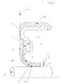
- Figures 1 to 7 each show an embodiment of a sealing ring.
- the sealing ring consists in each case a support ring 8 on which a unit consisting of sealing sleeve 1 and Seal 4 is set.
- the sealing sleeve 1 is in the Embodiments each made of a PTFE compound and has one Thickness that is at most 0.6 mm.
- a seal 4 is arranged, each in the exemplary embodiments shown here made of a polymer Material consists, the ratio of the thickness 5 of the sealing sleeve 1st to the thickness 6 of the seal 4 is at least 10. In the ones shown here In exemplary embodiments, the thickness 6 of the seal 4 is 0.05 mm.
- FIG. 1 A first exemplary embodiment of a sealing ring is shown in FIG.
- the Unit consisting of sealing sleeve 1 and seal 4 is in the direction of the space to be sealed 9 bulges and encloses the machine element 3, which is designed as a shaft in this exemplary embodiment, with radial preload on the outer circumference.
- the end face 15 of the Sealing sleeve 1 is in a radial plane 16 with the end face 17 of the support ring 8 arranged so that the sealing ring shown here is particularly compact Has dimensions in the axial direction.
- the support ring 8 consists in this Embodiment made of a deep-drawn sheet metal, to the radially outside a statically stressed seal 18 is vulcanized.
- the Seal 4 causes, as in the other exemplary embodiments also that medium to be sealed from the space to be sealed 9 not through the material of the sealing sleeve 1 in the direction of the environment 10 arrives.
- the seal 4 and the sealing sleeve 1 are in the area of each other facing surfaces bonded to each other in a liquid-tight manner.
- FIG 2 a second embodiment is shown, similar to that Embodiment from Figure 1.
- the embodiment from Figure 2 differs from the embodiment of Figure 1 in that the sealing sleeve 1 and the seal 4 on their mutually facing surfaces each additionally have a surface profile 11, 12 which are congruent to each other.
- the improved durability the connection does not only result from the increased surface area adhesive connection of sealing sleeve 1 and sealing 4 to one another, but also from the positive positioning of the two parts together.
- Figure 3 is a third embodiment of the sealing ring according to the invention shown, similar to the embodiment of Figure 1.
- the seal 4 has a longitudinal section on the side facing away from the sealing sleeve 1 considered, essentially wavy surface profiling 13 on, which is an improved compared to the embodiment of Figure 1 Heat dissipation from the seal 4 through a relatively enlarged surface and improved flexibility of the unit consisting of a sealing collar 1 and seal 4 causes.
- FIG 4 a fourth embodiment is shown, which takes advantage of Embodiments of Figures 2 and 3 combined.
- a very durable connection between the sealing sleeve 1 and the Seal 4 given by the surface profiles 11, 12 and on the other hand, due to the wavy surface profile 13, a good one Dissipation of heat from the sealing ring in the direction of the space to be sealed 9.
- FIG 5 is another embodiment of the invention Sealing rings shown, the sealing sleeve 1, as well as the seal 4, against the space 9 to be sealed in the direction of the environment 10 is bulged.
- the Sealing 4 with medium to be sealed from the space to be sealed 9 does not come into contact. Therefore 4 materials can be used for sealing be chosen, the flexibility of the sealing sleeve 1 as low as possible affect.
- FIG. 5 A sixth exemplary embodiment of a sealing ring is shown in FIG likewise, like the sealing ring from FIG. 5, a unit consisting of a sealing sleeve 1 and seal 4, which in the direction of the environment 10 is bulged.
- FIG. 7 shows a seventh exemplary embodiment of a sealing ring in which the seal 4 the end face 19 of the bulging in the axial direction Sealing sleeve 1 covered.
- the cover 21 encloses the one to be sealed Surface 2 is under radial prestress. Coverage 21 has an axial extent 20 that corresponds to the thickness 6 of the seal 4 equivalent. A diffusion of the medium to be sealed from the medium to be sealed Room 9, essentially axially parallel and parallel to the surface to be sealed 2 through the sealing collar 1 is thereby avoided; both one Diffusion of medium to be sealed in the radial as well as in the axial direction is excluded.
- the overlap 21 is not only based on the exemplary embodiment according to FIG. 7 limited.
- the exemplary embodiments corresponding to FIGS. 1 to 6 also can have a seal 4, the end face 19 of the in the axial Direction of bulging sealing sleeve 1 covered by the cover 21 and the surface 2 of the machine element 3 to be sealed under radial Prestressing encloses.
- the embodiment shown here 7 corresponds to the axial extent 20 of the overlap 21 of the Thickness 6 of the seal 4.
- the sealing sleeve has 1 on the side facing the machine element 3 in each case a return swirl 14, the medium to be sealed in the direction of promotes room 9 to be sealed.
Landscapes
- Engineering & Computer Science (AREA)
- General Engineering & Computer Science (AREA)
- Mechanical Engineering (AREA)
- Physics & Mathematics (AREA)
- Fluid Mechanics (AREA)
- Gasket Seals (AREA)
- Mechanical Sealing (AREA)
Abstract
Description
- Figur 1
- ein erstes Ausführungsbeispiel, bei dem die Dichtmanschette nur auf der dem abzudichtenden Maschinenelement zugewandten Seite eine Oberflächenprofilierung in Form eines Rückförderdralls aufweist,
- Figur 2
- ein zweites Ausführungsbeispiel, ähnlich dem Ausführungsbeispiel aus Figur 1, wobei sowohl die Dichtmanschette als auch die Versiegelung auf den einander zugewandten Seiten zusätzlich jeweils eine Oberflächenprofilierung aufweisen,
- Figur 3
- ein drittes Ausführungsbeispiel, ähnlich dem Ausführungsbeispiel aus Figur 1, wobei die Versiegelung zusätzlich auf der der Dichtmanschette abgewandten Seite eine wellenförmige Oberflächen-profilierung aufweist,
- Figur 4
- ein viertes Ausführungsbeispiel, ähnlich dem Ausführungsbeispiel aus Figur 2, wobei die Versiegelung zusätzlich auf der der Dichtmanschette abgewandten Seite eine wellenförmige Oberflächen-profilierung aufweist,
- Figur 5
- ein fünftes Ausführungsbeispiel, ähnlich dem Ausführungsbeispiel aus Figur 1, wobei die Einheit, bestehend aus Dichtmanschette und Versiegelung in Richtung der Umgebung vorgewölbt ist,
- Figur 6
- ein sechstes Ausführungsbeispiel, ähnlich dem Ausführungsbeispiel aus Figur 5,
- Figur 7
- ein siebtes Ausführungsbeispiel, das im Wesentlichen dem Ausführungsbeispiel aus Figur 6 entspricht, bei dem die Stirnseite der in axialer Richtung vorgewölbten Dichtmanschette jedoch von einer Überdeckung überdeckt ist, die die abzudichtende Fläche unter radialer Vorspannung anliegend umschließt.
Claims (17)
- Dichtring, umfassend eine Dichtmanschette aus polymerem Werkstoff, wobei die Dichtmanschette auf der der abzudichtenden Fläche eines Maschinenelements abgewandten Seite eine Versiegelung aufweist, dadurch gekennzeichnet, dass die Dicke (5) der Dichtmanschette (1) höchstens 0,6 mm und die Dicke (6) der Versiegelung (4) 0,005 bis 0,3 mm beträgt.
- Dichtring nach Anspruch 1, dadurch gekennzeichnet, dass die Dicke (5) der Dichtmanschette (1) höchstens 0,6 mm beträgt.
- Dichtring nach Anspruch 1, dadurch gekennzeichnet, dass die Dicke (6) der Versiegelung (4) 0,01 bis 0,1 mm beträgt.
- Dichtring nach einem der Ansprüche 1 bis 3, dadurch gekennzeichnet, dass das Verhältnis aus der Dicke (5) der Dichtmanschette (1) zur Dicke (6) der Versiegelung (4) 2 bis 120 beträgt.
- Dichtring nach Anspruch 4, dadurch gekennzeichnet, dass das Verhältnis zumindest 10 beträgt.
- Dichtring nach einem der Ansprüche 1 bis 5, dadurch gekennzeichnet, dass die Dichtmanschette (1) aus einem PTFE-Compound besteht.
- Dichtring nach einem der Ansprüche 1 bis 5, dadurch gekennzeichnet, dass die Versiegelung (4) aus einem polymeren Werkstoff besteht.
- Dichtring nach einem der Ansprüche 1 bis 7, dadurch gekennzeichnet, dass die Dichtmanschette (1) mittels einer Zwischenschicht (7) mit einem Stützring (8) aus zähhartem Werkstoff verbunden ist.
- Dichtring nach einem der Ansprüche 1 bis 8, dadurch gekennzeichnet, dass die Versiegelung (4) und die Zwischenschicht (7) einstückig ineinander übergehend und materialeinheitlich ausgebildet sind.
- Dichtring nach einem der Ansprüche 1 bis 9, dadurch gekennzeichnet, dass die Dichtmanschette (1) entgegen dem abzudichtenden Raum (9) in Richtung der Umgebung (10) vorgewölbt ist.
- Dichtring nach einem der Ansprüche 1 bis 10, dadurch gekennzeichnet, dass die Dichtmanschette (1) und die Versiegelung (4) auf ihren einander zugewandten Seiten jeweils eine Oberflächenprofilierung (11, 12) aufweisen.
- Dichtring nach Anspruch 11, dadurch gekennzeichnet, dass die Oberflächenprofilierungen (11, 12) von Dichtmanschette (1) und Versiegelung (4) kongruent gestaltet sind.
- Dichtring nach einem der Ansprüche 1 bis 12, dadurch gekennzeichnet, dass die Versiegelung (4) auf der der Dichtmanschette (1) abgewandten Seite eine, im Längsschnitt des Dichtrings betrachtet, im Wesentlichen wellenförmige Oberflächenprofilierung (13) aufweist.
- Dichtring nach einem der Ansprüche 1 bis 13, dadurch gekennzeichnet, dass die Dichtmanschette (1) auf der der abzudichtenden Fläche (2) zugewandten Seite einen in Richtung des abzudichtenden Raums (9) wirksamen Rückförderdrall (14) aufweist.
- Dichtring nach einem der Ansprüche 1 bis 14, dadurch gekennzeichnet, dass die Versiegelung (4) die Stirnseite (19) der in axialer Richtung vorgewölbten Dichtmanschette (1) überdeckt und die abzudichtende Fläche (2) unter radialer Vorspannung anliegend umschließt.
- Dichtring nach Anspruch 15, dadurch gekennzeichnet, dass die axiale Erstreckung (20) der Überdeckung (21) 0,005 bis 0,3 mm beträgt.
- Dichtring nach einem der Ansprüche 15 oder 16, dadurch gekennzeichnet, dass die axiale Erstreckung (20) der Überdeckung (21) der Dicke (6) entspricht.
Applications Claiming Priority (4)
| Application Number | Priority Date | Filing Date | Title |
|---|---|---|---|
| DE10115130 | 2001-03-27 | ||
| DE10115130 | 2001-03-27 | ||
| DE10206624A DE10206624A1 (de) | 2001-03-27 | 2002-02-15 | Dichtring |
| DE10206624 | 2002-02-15 |
Publications (3)
| Publication Number | Publication Date |
|---|---|
| EP1245873A2 true EP1245873A2 (de) | 2002-10-02 |
| EP1245873A3 EP1245873A3 (de) | 2004-01-28 |
| EP1245873B1 EP1245873B1 (de) | 2005-11-23 |
Family
ID=26008925
Family Applications (1)
| Application Number | Title | Priority Date | Filing Date |
|---|---|---|---|
| EP20020006463 Revoked EP1245873B1 (de) | 2001-03-27 | 2002-03-22 | Dichtring |
Country Status (2)
| Country | Link |
|---|---|
| EP (1) | EP1245873B1 (de) |
| DE (1) | DE50204990D1 (de) |
Citations (1)
| Publication number | Priority date | Publication date | Assignee | Title |
|---|---|---|---|---|
| DE3402366A1 (de) | 1984-01-25 | 1985-08-01 | Kaco Gmbh + Co, 7100 Heilbronn | Radialwellendichtring sowie verfahren zu dessen herstellung |
Family Cites Families (3)
| Publication number | Priority date | Publication date | Assignee | Title |
|---|---|---|---|---|
| US5183271A (en) * | 1990-01-25 | 1993-02-02 | Nok Corporation | Sealing device and manufacturing method of the same |
| EP1024318A3 (de) * | 1999-01-29 | 2001-04-25 | Freudenberg-NOK General Partnership | Dichtring mit Förderwirkung |
| AU5426200A (en) * | 1999-06-18 | 2001-01-09 | Nok Corporation | Lip-type high-pressure seal |
-
2002
- 2002-03-22 DE DE50204990T patent/DE50204990D1/de not_active Revoked
- 2002-03-22 EP EP20020006463 patent/EP1245873B1/de not_active Revoked
Patent Citations (1)
| Publication number | Priority date | Publication date | Assignee | Title |
|---|---|---|---|---|
| DE3402366A1 (de) | 1984-01-25 | 1985-08-01 | Kaco Gmbh + Co, 7100 Heilbronn | Radialwellendichtring sowie verfahren zu dessen herstellung |
Also Published As
| Publication number | Publication date |
|---|---|
| EP1245873B1 (de) | 2005-11-23 |
| DE50204990D1 (de) | 2005-12-29 |
| EP1245873A3 (de) | 2004-01-28 |
Similar Documents
| Publication | Publication Date | Title |
|---|---|---|
| EP0012133B1 (de) | Dichtung für den Spalt zwischen einer umlaufenden Welle und einer Gehäusebohrung gegenüber einem Gemisch aus einer Flüssigkeit und einem Gas | |
| EP1156241B1 (de) | Dichtmanschette, insbesondere für Einbauräume mit kleinen Abmessungen | |
| EP0033964B1 (de) | Radialwellendichtring | |
| DE3524461C2 (de) | ||
| EP1462686A1 (de) | Dichtring | |
| EP0133928B1 (de) | Radialwellendichtring | |
| DE2949839C2 (de) | Dichtring | |
| DE3219156C2 (de) | ||
| DE2745356C2 (de) | Dichtelement | |
| DE19728605C2 (de) | Stangen- oder Kolbendichtung | |
| EP1026428A2 (de) | Dichtring | |
| DE3150472A1 (de) | Radialwellendichtring | |
| EP0137092A2 (de) | Achs- oder Wellendichtung | |
| DE19648602C2 (de) | Dichtungsanordnung | |
| DE4225556C2 (de) | Zwischen radial nach innen weisenden Vorsprüngen einer Zylinderfläche abgestützte Stangenführung | |
| DE19539057A1 (de) | Radialwellendichtring | |
| DE10315370A1 (de) | Kassettendichtung | |
| EP0187891B1 (de) | Radialwellendichtring | |
| DE19726433C2 (de) | Dichtungsanordnung | |
| DE10206624A1 (de) | Dichtring | |
| EP1245873B1 (de) | Dichtring | |
| DE19934453C2 (de) | Dichtring | |
| EP0187890B1 (de) | Radialwellendichtring | |
| DE102004020965A1 (de) | Radialwellendichtring | |
| EP0750142A1 (de) | Dichtungsanordnung |
Legal Events
| Date | Code | Title | Description |
|---|---|---|---|
| PUAI | Public reference made under article 153(3) epc to a published international application that has entered the european phase |
Free format text: ORIGINAL CODE: 0009012 |
|
| AK | Designated contracting states |
Kind code of ref document: A2 Designated state(s): AT BE CH CY DE DK ES FI FR GB GR IE IT LI LU MC NL PT SE TR |
|
| AX | Request for extension of the european patent |
Free format text: AL;LT;LV;MK;RO;SI |
|
| PUAL | Search report despatched |
Free format text: ORIGINAL CODE: 0009013 |
|
| AK | Designated contracting states |
Kind code of ref document: A3 Designated state(s): AT BE CH CY DE DK ES FI FR GB GR IE IT LI LU MC NL PT SE TR |
|
| AX | Request for extension of the european patent |
Extension state: AL LT LV MK RO SI |
|
| 17P | Request for examination filed |
Effective date: 20040212 |
|
| 17Q | First examination report despatched |
Effective date: 20040402 |
|
| AKX | Designation fees paid |
Designated state(s): DE FR GB IT |
|
| GRAP | Despatch of communication of intention to grant a patent |
Free format text: ORIGINAL CODE: EPIDOSNIGR1 |
|
| GRAS | Grant fee paid |
Free format text: ORIGINAL CODE: EPIDOSNIGR3 |
|
| GRAA | (expected) grant |
Free format text: ORIGINAL CODE: 0009210 |
|
| AK | Designated contracting states |
Kind code of ref document: B1 Designated state(s): DE FR GB IT |
|
| PG25 | Lapsed in a contracting state [announced via postgrant information from national office to epo] |
Ref country code: IT Free format text: LAPSE BECAUSE OF FAILURE TO SUBMIT A TRANSLATION OF THE DESCRIPTION OR TO PAY THE FEE WITHIN THE PRESCRIBED TIME-LIMIT;WARNING: LAPSES OF ITALIAN PATENTS WITH EFFECTIVE DATE BEFORE 2007 MAY HAVE OCCURRED AT ANY TIME BEFORE 2007. THE CORRECT EFFECTIVE DATE MAY BE DIFFERENT FROM THE ONE RECORDED. Effective date: 20051123 Ref country code: GB Free format text: LAPSE BECAUSE OF FAILURE TO SUBMIT A TRANSLATION OF THE DESCRIPTION OR TO PAY THE FEE WITHIN THE PRESCRIBED TIME-LIMIT Effective date: 20051123 |
|
| REG | Reference to a national code |
Ref country code: GB Ref legal event code: FG4D Free format text: NOT ENGLISH |
|
| REF | Corresponds to: |
Ref document number: 50204990 Country of ref document: DE Date of ref document: 20051229 Kind code of ref document: P |
|
| ET | Fr: translation filed | ||
| GBV | Gb: ep patent (uk) treated as always having been void in accordance with gb section 77(7)/1977 [no translation filed] |
Effective date: 20051123 |
|
| PLBI | Opposition filed |
Free format text: ORIGINAL CODE: 0009260 |
|
| PLAX | Notice of opposition and request to file observation + time limit sent |
Free format text: ORIGINAL CODE: EPIDOSNOBS2 |
|
| 26 | Opposition filed |
Opponent name: KACO GMBH & CO. KG Effective date: 20060822 |
|
| PLBB | Reply of patent proprietor to notice(s) of opposition received |
Free format text: ORIGINAL CODE: EPIDOSNOBS3 |
|
| APBP | Date of receipt of notice of appeal recorded |
Free format text: ORIGINAL CODE: EPIDOSNNOA2O |
|
| APAH | Appeal reference modified |
Free format text: ORIGINAL CODE: EPIDOSCREFNO |
|
| APBQ | Date of receipt of statement of grounds of appeal recorded |
Free format text: ORIGINAL CODE: EPIDOSNNOA3O |
|
| PGFP | Annual fee paid to national office [announced via postgrant information from national office to epo] |
Ref country code: FR Payment date: 20100408 Year of fee payment: 9 |
|
| APBU | Appeal procedure closed |
Free format text: ORIGINAL CODE: EPIDOSNNOA9O |
|
| PGFP | Annual fee paid to national office [announced via postgrant information from national office to epo] |
Ref country code: DE Payment date: 20100323 Year of fee payment: 9 |
|
| RDAF | Communication despatched that patent is revoked |
Free format text: ORIGINAL CODE: EPIDOSNREV1 |
|
| RDAG | Patent revoked |
Free format text: ORIGINAL CODE: 0009271 |
|
| STAA | Information on the status of an ep patent application or granted ep patent |
Free format text: STATUS: PATENT REVOKED |
|
| 27W | Patent revoked |
Effective date: 20100610 |