EP1245839B1 - Combination of screw and screw driver bit - Google Patents
Combination of screw and screw driver bit Download PDFInfo
- Publication number
- EP1245839B1 EP1245839B1 EP00985868.9A EP00985868A EP1245839B1 EP 1245839 B1 EP1245839 B1 EP 1245839B1 EP 00985868 A EP00985868 A EP 00985868A EP 1245839 B1 EP1245839 B1 EP 1245839B1
- Authority
- EP
- European Patent Office
- Prior art keywords
- screw
- bit
- groove
- driver bit
- fitting groove
- Prior art date
- Legal status (The legal status is an assumption and is not a legal conclusion. Google has not performed a legal analysis and makes no representation as to the accuracy of the status listed.)
- Expired - Lifetime
Links
- 238000004519 manufacturing process Methods 0.000 description 10
- 230000005540 biological transmission Effects 0.000 description 8
- 230000004048 modification Effects 0.000 description 5
- 238000012986 modification Methods 0.000 description 5
- 230000015572 biosynthetic process Effects 0.000 description 2
- 239000002699 waste material Substances 0.000 description 2
- 239000000428 dust Substances 0.000 description 1
- 239000002184 metal Substances 0.000 description 1
- 238000004080 punching Methods 0.000 description 1
- 238000004064 recycling Methods 0.000 description 1
- 238000010079 rubber tapping Methods 0.000 description 1
- 238000000926 separation method Methods 0.000 description 1
- 238000007493 shaping process Methods 0.000 description 1
- 239000007779 soft material Substances 0.000 description 1
Images


Classifications
-
- F—MECHANICAL ENGINEERING; LIGHTING; HEATING; WEAPONS; BLASTING
- F16—ENGINEERING ELEMENTS AND UNITS; GENERAL MEASURES FOR PRODUCING AND MAINTAINING EFFECTIVE FUNCTIONING OF MACHINES OR INSTALLATIONS; THERMAL INSULATION IN GENERAL
- F16B—DEVICES FOR FASTENING OR SECURING CONSTRUCTIONAL ELEMENTS OR MACHINE PARTS TOGETHER, e.g. NAILS, BOLTS, CIRCLIPS, CLAMPS, CLIPS OR WEDGES; JOINTS OR JOINTING
- F16B23/00—Specially shaped nuts or heads of bolts or screws for rotations by a tool
-
- B—PERFORMING OPERATIONS; TRANSPORTING
- B25—HAND TOOLS; PORTABLE POWER-DRIVEN TOOLS; MANIPULATORS
- B25B—TOOLS OR BENCH DEVICES NOT OTHERWISE PROVIDED FOR, FOR FASTENING, CONNECTING, DISENGAGING OR HOLDING
- B25B15/00—Screwdrivers
- B25B15/001—Screwdrivers characterised by material or shape of the tool bit
- B25B15/004—Screwdrivers characterised by material or shape of the tool bit characterised by cross-section
- B25B15/005—Screwdrivers characterised by material or shape of the tool bit characterised by cross-section with cross- or star-shaped cross-section
-
- B—PERFORMING OPERATIONS; TRANSPORTING
- B21—MECHANICAL METAL-WORKING WITHOUT ESSENTIALLY REMOVING MATERIAL; PUNCHING METAL
- B21K—MAKING FORGED OR PRESSED METAL PRODUCTS, e.g. HORSE-SHOES, RIVETS, BOLTS OR WHEELS
- B21K1/00—Making machine elements
- B21K1/44—Making machine elements bolts, studs, or the like
- B21K1/46—Making machine elements bolts, studs, or the like with heads
- B21K1/463—Making machine elements bolts, studs, or the like with heads with recessed heads
-
- B—PERFORMING OPERATIONS; TRANSPORTING
- B21—MECHANICAL METAL-WORKING WITHOUT ESSENTIALLY REMOVING MATERIAL; PUNCHING METAL
- B21K—MAKING FORGED OR PRESSED METAL PRODUCTS, e.g. HORSE-SHOES, RIVETS, BOLTS OR WHEELS
- B21K1/00—Making machine elements
- B21K1/44—Making machine elements bolts, studs, or the like
- B21K1/46—Making machine elements bolts, studs, or the like with heads
- B21K1/48—Machines working with hammers, e.g. beating in a radial direction, for forming heads
-
- F—MECHANICAL ENGINEERING; LIGHTING; HEATING; WEAPONS; BLASTING
- F16—ENGINEERING ELEMENTS AND UNITS; GENERAL MEASURES FOR PRODUCING AND MAINTAINING EFFECTIVE FUNCTIONING OF MACHINES OR INSTALLATIONS; THERMAL INSULATION IN GENERAL
- F16B—DEVICES FOR FASTENING OR SECURING CONSTRUCTIONAL ELEMENTS OR MACHINE PARTS TOGETHER, e.g. NAILS, BOLTS, CIRCLIPS, CLAMPS, CLIPS OR WEDGES; JOINTS OR JOINTING
- F16B23/00—Specially shaped nuts or heads of bolts or screws for rotations by a tool
- F16B23/0007—Specially shaped nuts or heads of bolts or screws for rotations by a tool characterised by the shape of the recess or the protrusion engaging the tool
- F16B23/0023—Specially shaped nuts or heads of bolts or screws for rotations by a tool characterised by the shape of the recess or the protrusion engaging the tool substantially cross-shaped
Definitions
- the present invention relates to a combination of a screw and a screw driver bit that ensures tight fitting of the bit-fitting groove of cross groove formed in the screw head, and the screw driver bit to fit into the bit-fitting groove, and can rapidly and securely achieve the attaching and detaching of the screw always by proper torque transmission.
- An example of a screw and screw driver bit is known from WO-A-99/43472 .
- FIGS. 12 and 13 show a conventional screw having a cross groove
- FIG. 14 shows a screw driver bit for this cross-grooved screw
- FIG. 15 shows the state of fitting of the above-described screw and the screw driver bit.
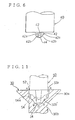
- the conventional screw 10 shown in FIG. 12 is provided, on a screw head part 10a thereof, with a cross groove 12.
- This cross groove 12 is configured in such a manner that a specified tilted groove part 12a is formed in the direction from each end edge part so as to extend to the center part of a screw neck part 10b and, at the same time, in the bottom part thereof is formed a roughly conical bottom face 14 with a gentle inclination.
- reference numeral 13 each denotes a tapered side wall part formed between adjacent cross grooves 12. That is, the cutting-edge part of a screw driver bit, which will be described later, abuts and engages with this tapered side wall part 13.
- taper connection faces 17a, 17b which extend from the position of the conical bottom face 14 to the opening edge part of the cross groove 12 of the screw head part 10a and also against these taper connection faces 17a, 17b abuts and engages a portion of the cutting-edge part of a screw driver bit, which will be described later.
- a conventional screw driver bit 20 shown in FIG. 14 is configured in such a manner that the screw driver bit is provided with cutting-edge parts 22, each of which fits into the respective cross grooves 12 of the above-described screw 10, and there are formed extended cutting-edge parts 22a, each of which extends so as to match the shape of the tilted groove parts 12a formed in the direction from the end edge parts of the above-described cross groove 12 to the center part of the screw neck part 10b.
- reference numeral 23 denotes tapered side wall parts formed on both side faces of each of the above-described cutting-edge parts 22 and extended cutting-edge parts 22a. That is, these tapered side wall parts 23 abut and engage against the tapered side wall parts 13 formed in the cross groove 12 of the above-described screw 10.
- the cross groove 12 of the screw head part 10a has a specified tilted groove part 12a which is formed in the direction from the end edge part of the cross groove to the center part of the screw neck part 10b and, on the other hand, the screw driver bit 20 which fits into the screw is configured in such a manner that the ridgeline part of the extended cutting-edge part 22a matches the shape of the above-described tilted groove part 12a and fits into the above-described cross groove 12 and, furthermore, this ridgeline part of the extended cutting-edge part 22a is formed in such a manner that the width increases gradually in the direction from the leading end thereof to the rear.
- the shape of the cross groove 12 of the conventional screw 10 is such that, as shown in FIG. 13 , in order to facilitate the fitting of the leading end of the screw driver bit 20, the groove width of the cross groove 12 is formed in a larger size than the width of the ridgeline part of the extended cutting-edge part 22a of the screw driver bit 20, whereas the areas of the tapered side wall part 13 and taper connection faces 17a, 17b formed in the boundary parts between adjacent cross grooves 12, 12 and in the corner parts thereof are relatively small.
- the occurrence of the come-out phenomenon accelerates the wear of the leading end parts of the bit, i.e., the cutting-edge part 22 and extended cutting-edge part 22a, and the wear of these parts further promotes the occurrence of the above-described come-out phenomenon, with the result that there is a drawback that the damage to the screw groove also increases.
- a screw having a generally vertical end wall part, a tilted groove part, and a conical bottom face is known from prior art document JP-A-3 292 407 .
- a screw head having grooves which are generally widening toward the end, and an opening angle between the grooves, which is a little sharper than a right angle, is known from WO-A-99/43472 .
- EP-A1-0 933 538 discloses a header punch for manufacturing a screw.
- a specified tilted groove part is formed in the direction from the end edge part of the bit-fitting groove to the center part of a screw neck part, and a roughly conical bottom face is formed at a cross center part, by forming the end edge part of the above-described bit-fitting groove as a generally vertical end wall part of a specified depth, by forming a groove part with an inclination angle ⁇ of about 45° in the direction from the lower edge part of the end wall part to the conical bottom face at the center part of the screw neck part, and further by forming the conical bottom face with a gentle inclination angle ⁇ of approximately 28°, it is possible to securely prevent the come-out phenomenon of the screw driver bit during the fitting of the screw driver bit into the screw groove, to substantially reduce damage to the screw by increasing
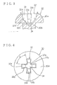
- FIGS. 1 and 2 show an example of a screw related to the invention. That is, in FIGS. 1 and 2 , reference numeral 30 denotes the screw related to the invention, and a bit-fitting groove 32 is provided in a head part 30a of this screw 30. Incidentally, this bit-fitting groove 32 is configured as a cross groove which intersects in plus (+) form at the center part of the screw head part 30a.
- This bit-fitting groove 32 is constituted by the dimension m of the opening (portion A-A) and the dimension g of the groove bottom part (portion B-B) in accordance with JIS (Japanese Industrial Standard) which have hitherto been publicly known. That is, from the opening end edge part (portion A-A) of the bit-fitting groove 32 to a specified depth are formed end wall parts 32a each having a draft taper (draft angle ⁇ of header punch) of about 1.5° to 5° and a tilted groove part 32b with an inclination angle ⁇ of about 45° is formed in the direction from the lower edge part 32a' of this end wall part 32a (portion C-C) to the center part of the screw head part 30a, and a conical bottom face 34 with a gentle inclination angle ⁇ of about 28° is then formed in the direction from the point of intersection (portion B-B) between this tilted groove part 32b and the dimension of the bottom part in accordance with JIS to the above-described center part.
- FIGS. 3 and 4 show another example of a screw related to the invention. That is, in FIG. 4 , a screw 30 of this example is such that a screw head part 30a is formed in pan shape and the structure of a bit-fitting groove 23 provided in the screw head part 30a is the same as the bit-fitting groove 23 of the screw 30 whose screw head part 30a is formed in dish shape in the example shown in the above-described FIG. 1 . Therefore, the same reference numerals are given to the same component parts and their detailed description is omitted.
- opposed side wall parts 33 of the bit-fitting groove 32 are formed grooves with a width generally widening toward the end 33a, 33b from the center part of the screw head part 30a outward in the radial direction.
- the screw related to the invention is also effective as a plus-and-minus screw (i.e., a screw with a cross grooved and slotted head) that permits the application of a conventional plus screw driver bit and a conventional slotted head screw driver bit.
- a plus-and-minus screw i.e., a screw with a cross grooved and slotted head
- FIG. 5(a) for a bit-fitting groove 32 into which the leading end of the cutting-edge part of a plus screw driver bit fits, grooves with a width widening toward the end 33a, 33b can be formed in the same manner as with the example shown in the above-described FIG. 4 .
- the section structure of a plus-and-minus screw 30' is basically the same as described in each example shown in FIGS. 1 and 3 and hence its illustration is omitted.
- one groove 32B in a pair of grooves 32A and 32B that intersect in cross form in the center part of the screw headpart 30a is formed as a horizontal groove with a sufficient width and depth so that the groove 32B can abut and engage with the cutting-edge part of the slotted head screw driver bit.
- the structure of other portions is the same as the structure of the screw head part 30a of the screw 30 shown in the above-described FIG. 4 and, therefore, the same reference numerals are given to the same component parts and their detailed description is omitted.
- FIG. 5(b) shows an example of modification of plus-and-minus screw 30' shown in the above-described FIG. 5(a) . That is, in plus-and-minus screw 30' of the above-described example, the grooves with a width widening toward the end 33a, 33b, which are formed for the groove 32B that can fit and abut against the cutting-edge part of the slotted head screw driver bit, in a pair of grooves 32A and 32B intersecting in cross form, are configured so as not to exceed the width of the horizontal groove that fits and abuts against the cutting-edge part of the slotted head screw driver bit.
- the maximum groove width of the grooves with a width widening toward the end 33a, 33b in the above-described groove 32B is configured so as to exceed the width of the above-described horizontal groove, as shown in FIG. 5 (b) .
- the abutting area (driving area) can be increased.
- the bit-fitting groove 32 of the screw related to the invention is based on the hitherto publicly known dimension m of the opening (portion A-A) and dimension g of the groove bottom part (portion B-B) in accordance with JIS (Japanese Industrial Standard).
- portion C-C By positioning the lower edge part 32a' of the end wall part 32a (portion C-C) at a point of intersection between the draft taper angle ⁇ from the opening end edge part (portion A-A) to a specified depth and the inclination angle ⁇ of about 45° from a point (portion B-B) which provides the base part of the conical bottom face 34 with a specified gentle inclination angle ⁇ , and by providing the tilted groove part 32b set by this positioning, through the application of not only a conventional plus screw driver bit, but also a screw driver bit of a structure which will be described later, it is possible to expand the area in which the screw driver bit can give a rotating driving force to the screw (hereinafter referred to as the driving area) and, at the same time, it is possible, to securely prevent the come-out phenomenon of the screw driver bit and to achieve well-balanced torque transmission to the screw.
- the driving area the area in which the screw driver bit can give a rotating driving force to the screw
- the setting of the inclination angle ⁇ of the above-described tilted groove part 32b, particularly in a screw with the screw head part 30a formed in dish shape enables the wall thickness of a boundary portion between the screw head part 30a and the screw neck part 30b to be maintained at an appropriate value during the formation of the bit-fitting groove 32 and, therefore, it is possible to sufficiently increase the strength of the screw during a screw tightening operation, thus providing an advantage.
- the bit-fitting groove 32 of this shape is formed by means of a header punch, it is possible to keep the life of the above-described header punch long by reducing the wear of the leading end part thereof, thus providing another advantage.
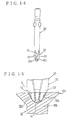
- FIG. 6 shows an example of a header punch 40 for manufacturing the screw 30 related to the invention in Example 1 shown in FIG. 1 . That is, the header punch 40 of this example is intended for use in punching and shaping the bit-fitting groove 32 in the screw head part 30a of the screw 30 shown in FIG. 1 .
- the header punch 40 of this example is provided with projecting pieces 42 having tilted edge parts 42a, 42b for forming the end wall part 32a with a specified draft angle ⁇ and the tilted groove part 32b with an inclination angle ⁇ of about 45° in the end edge part of bit-fitting groove 32 of the screw head part 30a, and has a conical projection 44 for forming the conical bottom face 34 with a gentle inclination angle ⁇ of about 28° in the direction from these projecting pieces 42 to the center part of the screw neck part 30b.
- header punches for manufacturing the screws shown in the above-described Examples 2 and 3 it is possible to configure specified header punches by making the design change of the shape of the above-described projecting pieces 42 according to the shape of the screws in each example.
- FIGS. 7 and 8 show an example of a screw driver bit related to the invention. That is, in FIGS. 7 and 8 , reference numeral 50 denotes a main portion of a screw driver bit of this example, and the leading end of the cutting-edge part of this screw driver bit is configured so as to fit into the bit-fitting groove 32 formed as a cross groove in the center part of screw head part 30a of the above-described screw 30 related to the invention.
- the screw driver bit 50 of this example fits into the bit-fitting groove 32 of the above-described screw 30, is provided with flat cutting-edge parts 52 which respectively engage with the end wall part 32a and tilted groove part 32b formed in the end edge part of this bit-fitting groove 32, and has a conical projection 54 which sets the leading end face of the above-described flat cutting-edge part 52 at an inclination angle ⁇ of about 1° to 45° and preferably 25° to 35° with respect to a horizontal plane according to the tilted groove part 32b and conical bottom part 34, which are formed in the direction from the end wall part 32a of the above-described bit-fitting groove 32 to the center part of the screw neck part 30b.
- reference numeral 53 denotes a generally vertical side wall part, which is formed on both sides of each of the above-described flat cutting-edge part 52 and for which a certain amount of taper is allowed. Therefore, this side wall part 53 abuts and engages against the side wall part 33 formed in the bit-fitting groove 32 of the above-described screw 30. Therefore, the engagement of these driving faces can ensure a sufficiently large engagement area and hence the come-out phenomenon that occurred in a combination of a conventional screw and a conventional screw driver bit can be effectively prevented.
- the side wall part 53 at the leading end of each of the above-described flat cutting-edge parts 52 can be configured in a shape which matches the grooves with a width widening toward the end 33a, 33b in the side wall part 33 formed in the bit-fitting groove 32 of the above-described screw 30, i.e., as side wall parts with a width widening toward the end 53a, 53b (refer to FIG. 8 ).
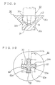
- FIG. 9 shows the connected state between the screw 30 shown in FIG. 1 and the screw driver bit 50 shown in FIG. 7 . That is, in this case, as shown in FIG. 9 , when the flat cutting-edge part 52 formed at the leading end of the screw driver bit 50 abuts against the bit-fitting groove 32 formed in the screw head part 30a of the screw 30, because of the formation of the leading end face of the flat cutting-edge part 52 as the conical projection 54, the contact with the opening edge part of the above-described bit-fitting groove 32 provides very small contact constituted by a point or a line and, at the same time, the mutual positioning of the center parts is easily and rapidly achieved, whereby the wear of the screw head part 30a and damage thereto are reduced and it becomes possible to rapidly perform an appropriate connection of the screw driver bit 50 to the screw 30.
- FIG. 10 shows the connected state between the screw 30 shown in FIG. 4 and the screw driver bit 50 shown in FIG. 8 . That is, in this case, as shown in FIG. 10 , because the side wall parts 53 at the leading end of the flat cutting-edge parts 52 of the screw driver bit 50 are configured as side wall parts with a width widening toward the end 53a, 53b so as to fit into the grooves with a width widening toward the end 33a, 33b, which are formed in the bit-fitting groove 32 of the screw 30, during the abutment of the cutting-edge part 52 of the screw driver bit 50 against each of the side wall parts (T1, T2, T3, T4) of bit-fitting groove 32 of the screw 30, an appropriate engagement between the screw and the screw driver bit 50 can be achieved by minimizing the clearances between the above-described grooves 33a, 33b and the above-described side wall parts 53a, 53b.
- a torque ⁇ 1 acting on each of the above-described side walls can be directed toward the side of the screw neck part 30b from the tangential direction ⁇ 0 of the screw head part 30a in which the cutting-edge part 52 of the above-described screw driver bit 50 is fitted and, therefore, the come-out phenomenon of the screw driver bit 50 can be securely prevented and well-balanced torque transmission to the screw 30 can be achieved.
- the cutting-edge part can be caused to abut against the side wall parts (T1, T2) of one groove 32A and simultaneously against the side wall parts (T3, T4) of the other groove 32B and well-balanced torque transmission can be achieved.
- the plus-and-minus screw 30' shown in FIG. 5(b) it is possible to increase the abutting area (driving area) of the cutting-edge part of the screw driver bit against the side wall parts (T3, T4) of the above-described groove 32B and this provides the advantage that better-balanced torque transmission can be achieved and the like.
- the side wall parts 53 at the leading end of the flat cutting-edge parts 52 of the screw driver bit 50 are configured as side wall parts with a width widening toward the end 53a, 53b so as to fit into the grooves with a width widening toward the end 33a, 33b, which are formed in the bit-fitting groove 32 of the above-described plus-and-minus screw 30' (refer to FIG. 8 ), during the abutment of the cutting-edge part 52 of this screw driver bit 50 against each of the side wall parts of bit-fitting groove 32 of the plus-and-minus screw 30', an appropriate engagement between the plus-and-minus screw 30' and the screw driver bit can be achieved by eliminating the clearance ⁇ as shown in FIG. 5 .
- FIG. 11 shows an example of modifications of the screw related to the invention shown in FIG. 1 and of the screw driver bit shown in FIG. 7 . That is, in FIG. 11 , for the structure of the tilted groove part 32b with an inclination angle ⁇ of about 45°, which is formed in the direction from the lower edge part 32a' of the end edge part 32a of bit-fitting groove 32 of the screw 30 shown in FIG. 1 to the conical bottom face 34 at the center part of the screw neck part 30b, the above-described tilted groove part is bulged 32b' in curved form inward to the bit-fitting groove 32.
- the screw related to the invention is formed so that a bit-fitting groove formed of a cross groove is provided in a screw head part, a specified tilted groove part is formed in the direction from the end edge part of the bit-fitting groove to the center part of a screw neck part, and a roughly conical bottom face is formed at a cross center part, wherein the end edge part of the above-described bit-fitting groove is formed as a generally vertical end wall part of a specified depth, that a groove part with an inclination angle ⁇ of about 45° is formed in the direction from the lower edge part of the end wall part to the conical bottom face at the center part of the screw neck part, and further that the conical bottom face is formed with a gentle inclination angle ⁇ of approximately 28°.
- the strength of the screw can be sufficiently increased during a screw tightening operation and, at the same time, the wear of the leading end part of the header punch is reduced during the manufacturing of the screw, a conventional plus screw driver bit can used, the come-out phenomenon of the screw driver bit during a screw tightening operation is securely prevented, and a well-balanced torque transmission to the screw can be achieved.
- the screw driver bit is provided, at the leading end thereof, with a flat cutting-edge part in which is formed a generally vertical end edge part that fits along a generally vertical end wall part of a bit-fitting groove of a screw head part, and the leading end face of this cutting-edge part is formed as a conical projection having an inclination angle of about 1° to 45° with respect to a horizontal plane so as to fit into the above-described screws related to the invention.
- this screw driver bit provides many excellent advantages: for example, the driving area of the screw driver bit relative to the screw can be expanded, whereby the come-out phenomenon of the screw driver bit can be securely prevented and, at the same time, a well-balanced torque transmission to the screw is achieved, with the result that a rapid screw tightening operation and an improvement in the operation efficiency can be easily achieved.
- the screw related to the invention is configured so that basically, the taper contact area relative to the whole of the bit-fitting groove is partial and small in the engagement with the screw driver bit, and besides the area of the side wall part of the bit-fitting groove against which the side wall part of the leading end of the screw driver bit abuts is expanded.
- an appropriate screw tightening operation and an appropriate screw removal operation can be achieved without causing damage (reference numeral 15) to a portion of the bit-fitting groove, for example as shown in FIG. 13 , and without causing the come-out phenomenon.
- the screw driver bit can be rotated by ensuring fitting with the axis of the screw and the axis of the screw driver bit always kept in a coaxial state. Therefore, a screw tightening operation by an appropriate torque can always be achieved rapidly by smoothly transmitting a rotating force of the screw driver bit to the screw without causing the come-out phenomenon and damage to the screw etc.
Landscapes
- Engineering & Computer Science (AREA)
- Mechanical Engineering (AREA)
- General Engineering & Computer Science (AREA)
- Details Of Spanners, Wrenches, And Screw Drivers And Accessories (AREA)
- Forging (AREA)
- Hand Tools For Fitting Together And Separating, Or Other Hand Tools (AREA)
Description
- The present invention relates to a combination of a screw and a screw driver bit that ensures tight fitting of the bit-fitting groove of cross groove formed in the screw head, and the screw driver bit to fit into the bit-fitting groove, and can rapidly and securely achieve the attaching and detaching of the screw always by proper torque transmission. An example of a screw and screw driver bit is known from
WO-A-99/43472 - A conventional general combination of a screw and a screw driver bit, which is configured as shown in
FIGS. 12 to 15 , is known. That is,FIGS. 12 and 13 show a conventional screw having a cross groove,FIG. 14 shows a screw driver bit for this cross-grooved screw, andFIG. 15 shows the state of fitting of the above-described screw and the screw driver bit. - The
conventional screw 10 shown inFIG. 12 is provided, on a screw head part 10a thereof, with across groove 12. Thiscross groove 12 is configured in such a manner that a specifiedtilted groove part 12a is formed in the direction from each end edge part so as to extend to the center part of ascrew neck part 10b and, at the same time, in the bottom part thereof is formed a roughlyconical bottom face 14 with a gentle inclination. Incidentally, inFIG. 12 ,reference numeral 13 each denotes a tapered side wall part formed betweenadjacent cross grooves 12. That is, the cutting-edge part of a screw driver bit, which will be described later, abuts and engages with this taperedside wall part 13. Furthermore, in the adjacent corner parts of each of the above-describedtilted groove parts 12a are formed taper connection faces 17a, 17b, which extend from the position of theconical bottom face 14 to the opening edge part of thecross groove 12 of the screw head part 10a and also against these taper connection faces 17a, 17b abuts and engages a portion of the cutting-edge part of a screw driver bit, which will be described later. - On the other hand, a conventional
screw driver bit 20 shown inFIG. 14 is configured in such a manner that the screw driver bit is provided with cutting-edge parts 22, each of which fits into therespective cross grooves 12 of the above-describedscrew 10, and there are formed extended cutting-edge parts 22a, each of which extends so as to match the shape of thetilted groove parts 12a formed in the direction from the end edge parts of the above-describedcross groove 12 to the center part of thescrew neck part 10b. Incidentally, inFIG. 14 ,reference numeral 23 denotes tapered side wall parts formed on both side faces of each of the above-described cutting-edge parts 22 and extended cutting-edge parts 22a. That is, these taperedside wall parts 23 abut and engage against the taperedside wall parts 13 formed in thecross groove 12 of the above-describedscrew 10. - According to a combination of the
conventional screw 10 andscrew driver bit 20 thus configured, as shown inFIG. 15 , by causing thescrew 10 and thescrew driver bit 20 to fit into each other, as described above, each of the cutting-edge parts 22 of thescrew driver bit 20 and each of the extended cutting-edge parts 22a fit into thetilted groove parts 12a of thecross groove 12 and theside wall parts 23 of the above-described cutting-edge parts 22 and extended cutting-edge parts 22a abut against the taperedside wall parts 13 in thecross groove 12 of thescrew 10. Therefore, by rotating thescrew driver bit 20, a prescribed torque can be transmitted to thescrew 10. That is, it is possible to perform the attaching and detaching of the screw in a specified object to be mounted. - However, according to the combination of the
conventional screw 10 andscrew driver bit 20 configured as mentioned above, as shown inFIG. 15 , thecross groove 12 of the screw head part 10a has a specifiedtilted groove part 12a which is formed in the direction from the end edge part of the cross groove to the center part of thescrew neck part 10b and, on the other hand, thescrew driver bit 20 which fits into the screw is configured in such a manner that the ridgeline part of the extended cutting-edge part 22a matches the shape of the above-describedtilted groove part 12a and fits into the above-describedcross groove 12 and, furthermore, this ridgeline part of the extended cutting-edge part 22a is formed in such a manner that the width increases gradually in the direction from the leading end thereof to the rear. In addition, also the taperedside wall part 23 formed in each cutting-edge part 22 of thescrew driver bit 20 abuts and engages with the taperedside wall part 13 formed in thecross groove 12 of thescrew 10. Therefore, when the above-describedscrew driver bit 20 is rotated in a prescribed direction, the resulting contact between the above-describedscrew driver bit 20 and thecross groove 12 is such a state that can be said to be totally tapered contact, with the result that the leading end of thescrew driver bit 20 tends to come out along the inclined plane of thetilted groove part 12a of the above-described cross groove 12 (indicated by an arrow inFIG. 15 ), leading to the occurrence of what is called a come-out phenomenon. - In particular, the shape of the
cross groove 12 of theconventional screw 10 is such that, as shown inFIG. 13 , in order to facilitate the fitting of the leading end of thescrew driver bit 20, the groove width of thecross groove 12 is formed in a larger size than the width of the ridgeline part of the extended cutting-edge part 22a of thescrew driver bit 20, whereas the areas of the taperedside wall part 13 and taper connection faces 17a, 17b formed in the boundary parts betweenadjacent cross grooves screw driver bit 20 large loads are applied to the above-described taperedside wall parts 13 and taper connection faces 17a, 17b and the screw tightening resistance is large, the above-described taperedside wall part 13 and taper connection faces 17a, 17b are gradually damaged as indicated byshaded portions 15 inFIG. 13 . Therefore, if these damaged portions (shaded portions 15) are expanded, the occurrence of the come-out phenomenon of the above-describedscrew driver bit 20 becomes frequent, eventually making a screw tightening operation impossible. - Incidentally, the occurrence of this come-out phenomenon brings about the drawback that the cutting-edge part at the leading end of the screw driver bit is worn, for example, in the case of a tapping screw, because the design surface hardness of this screw is high. Also, in the case of a clutch-type automatic screw driver having a torque control function, there is a drawback that when the come-out phenomenon occurs during screw tightening, the operator cannot judge whether the screw has been securely attached with an appropriate torque.
- In order to prevent the come-out phenomenon of the above-described
screw driver bit 20 from these standpoints, in the rotation of thescrew driver bit 20 it is necessary to apply a thrust which strongly pushes the screw driver bit against thescrew groove 12a. However, although there is no problem when the object to which the screw is to be attached is a rigid body such as metal, in the case of a precision component etc. there is a drawback that these objects are damaged. - Also, the occurrence of the come-out phenomenon accelerates the wear of the leading end parts of the bit, i.e., the cutting-
edge part 22 and extended cutting-edge part 22a, and the wear of these parts further promotes the occurrence of the above-described come-out phenomenon, with the result that there is a drawback that the damage to the screw groove also increases. - Furthermore, although it is possible to prevent the above-described come-out phenomenon by applying an excessive thrust to the above-described
screw driver bit 20, on the other hand an accurate torque cannot be transmitted to the screw and the magnitude of torque applied to thescrew driver bit 20 differs from operator to operator, with the result that there is a drawback that variations occur in the screw tightening torque. - On the other hand, when screw tightening is manually performed, it costs the operator great labor and fatigue to perform the operation of rotating the
screw driver bit 20, with the screw driver bit being sufficiently pushed against the screw. - Also, according to the combination of the above-described
conventional screw 10 andscrew driver bit 20, when screw attaching is performed by use of a manual tool or motor-driven tool, in the fitting of the leading end parts of the bit into the screw groove it is difficult to perform the rotating operation of the screw while keeping the axis of the screw and the axis of the screw driver bit in a coaxial state. Therefore, when there is an inclination between the axis of the screw and the axis of the screw driver bit, there is a drawback that the above-described come-out phenomenon occurs frequently and that besides the damage to the screw groove also occurs frequently, thereby reducing the working efficiency of screw tightening operation and, at the same time, incurring waste of expenses caused by the consumption of damaged screws. - Moreover, also in the screw detaching work, the same come-out phenomenon and damage to the screw groove are apt to occur and, in this case, the detaching of the screw becomes impossible and hence it becomes unavoidable to break a portion of the object to which the screw is attached. In particular, in the case of occurrence of the clogging of the interior of the screw groove with dust and the like, the occurrence of the above-described situation becomes remarkable and, for example, there is a drawback that separation work for the recycling of waste materials involving the detaching of the screw becomes complicated.
- A screw having a generally vertical end wall part, a tilted groove part, and a conical bottom face is known from prior art document
JP-A-3 292 407 - A screw head having grooves which are generally widening toward the end, and an opening angle between the grooves, which is a little sharper than a right angle, is known from
WO-A-99/43472 -
EP-A1-0 933 538 discloses a header punch for manufacturing a screw. - It is the object of the invention to provide a combination of a screw and a screw driver bit in which by improving the structure of a groove part in a cross groove of the screw, damage to the screw as in a conventional screw is prevented by effectively preventing the come-out phenomenon of the screw driver bit and in which even if the cross groove part of the screw is damaged, a proper and rapid screw tightening operation can always be achieved and the working efficiency can be remarkably increased, and a header punch for manufacturing the screw.
- This object is solved by the combination of features of claim 1.
- The present inventors devoted themselves to conducting a series of research and trial manufacture and, as a result, found out that, in a screw which is formed so that a bit-fitting groove formed of a cross groove is provided in a screw head part, a specified tilted groove part is formed in the direction from the end edge part of the bit-fitting groove to the center part of a screw neck part, and a roughly conical bottom face is formed at a cross center part, by forming the end edge part of the above-described bit-fitting groove as a generally vertical end wall part of a specified depth, by forming a groove part with an inclination angle β of about 45° in the direction from the lower edge part of the end wall part to the conical bottom face at the center part of the screw neck part, and further by forming the conical bottom face with a gentle inclination angle α of approximately 28°, it is possible to securely prevent the come-out phenomenon of the screw driver bit during the fitting of the screw driver bit into the screw groove, to substantially reduce damage to the screw by increasing the strength of the screw, and besides to achieve well-balanced torque transmission to the screw.
-
-
FIG. 1 is an essential sectional side view which shows an embodiment of a screw related to the invention; -
FIG. 2 is a plan view of the head part of the screw shown inFIG. 1 ; -
FIG. 3 is an essential sectional side view which shows another embodiment of a screw related to the invention; -
FIG. 4 is a plan view of the head part of the screw shown inFIG. 3 ; -
FIG. 5 (a) is a plan view of the head part of a screw which shows a further embodiment related to the invention; -
FIG. 5 (b) is a plan view of the head part of a screw which shows an example of modification ofFIG. 5(a) ; -
FIG. 6 is an essential side view of a header punch for manufacturing screws for forming the head part of the screw shown inFIG. 1 ; -
FIG. 7 is an essential enlarged side view which shows an embodiment of a screw driver bit related to the invention; -
FIG. 8 is an essential enlarged perspective view of the screw driver bit shown inFIG. 7 ; -
FIG. 9 is an essential enlarged sectional side view which shows how a screw driver bit of the invention fits into the screw shown inFIG. 1 ; -
FIG. 10 is an essential enlarged sectional plan view of a screw head part which shows how a screw driver bit of the invention fits into the screw shown inFIG. 4 ; -
FIG. 11 is an essential sectional side view which shows another embodiment of a screw related to the invention and an outline of the fitting state of a screw driver bit which fits into this screw; -
FIG. 12 is an essential sectional side view of a conventional cross-grooved screw; -
FIG. 13 is a plan view of the head part of the cross-grooved screw shown inFIG. 12 ; -
FIG. 14 is an essential side view of a screw driver bit for conventional cross-grooved screws; and -
FIG. 15 is an essential sectional side view which shows the connected state between the screw shown inFIG. 12 and the screw driver bit shown inFIG. 14 . -
30 Screw 30' Plus-and- minus screw 30a Screw head part 30b Screw neck part 32 Bit- fitting groove 32A, 32B Groove of plus-and- minus screw 32a End edge part 32a' Lower edge part 32b Tilted groove part 32b' Bulge in curved form 33 Side wall part 33a, 33b Groove with a width widening toward the end 34 Conical bottom face 37a, 37b Taper connection face 40 Header punch 42 Projecting piece 42a, 42b Tilted edge part 44 Conical projection 50 Screw driver bit 52 Flat cutting- edge part 53 Side wall part 53a, 53b Side wall part with a width widening toward the end 54 Conical projection 54a Concavity in curved form - Next, embodiments of a combination of a screw and a screw driver bit related to the invention and a header punch for its manufacture will be described below by referring to attached drawings.
-
FIGS. 1 and 2 show an example of a screw related to the invention. That is, inFIGS. 1 and 2 ,reference numeral 30 denotes the screw related to the invention, and a bit-fitting groove 32 is provided in ahead part 30a of thisscrew 30. Incidentally, this bit-fittinggroove 32 is configured as a cross groove which intersects in plus (+) form at the center part of thescrew head part 30a. - This bit-fitting
groove 32 is constituted by the dimension m of the opening (portion A-A) and the dimension g of the groove bottom part (portion B-B) in accordance with JIS (Japanese Industrial Standard) which have hitherto been publicly known. That is, from the opening end edge part (portion A-A) of the bit-fittinggroove 32 to a specified depth are formedend wall parts 32a each having a draft taper (draft angle γ of header punch) of about 1.5° to 5° and a tiltedgroove part 32b with an inclination angle β of about 45° is formed in the direction from thelower edge part 32a' of thisend wall part 32a (portion C-C) to the center part of thescrew head part 30a, and a conical bottom face 34 with a gentle inclination angle α of about 28° is then formed in the direction from the point of intersection (portion B-B) between this tiltedgroove part 32b and the dimension of the bottom part in accordance with JIS to the above-described center part. - Furthermore, in the
screw 30 of this example, as shown inFIG. 2 , at the adjacent corner parts of the above-described bit-fittinggroove 32 are respectively formed taper connection faces 37a, 37b which extend from the position of the conical bottom face 34 to the opening edge part of the bit-fittinggroove 32 in thescrew head part 30a in the same manner as with the conventional cross-grooved screw shown inFIG. 11 . -
FIGS. 3 and 4 show another example of a screw related to the invention. That is, inFIG. 4 , ascrew 30 of this example is such that ascrew head part 30a is formed in pan shape and the structure of a bit-fittinggroove 23 provided in thescrew head part 30a is the same as the bit-fittinggroove 23 of thescrew 30 whosescrew head part 30a is formed in dish shape in the example shown in the above-describedFIG. 1 . Therefore, the same reference numerals are given to the same component parts and their detailed description is omitted. - However, in the
screw 30 of this example, as shown inFIG. 4 , in opposedside wall parts 33 of the bit-fittinggroove 32 are formed grooves with a width generally widening toward theend screw head part 30a outward in the radial direction. - Thus, in the
screw 30 of this example, by forming the above-described grooves with a width widening toward theend screw 30 from the bit-fittinggroove 32 can be effectively prevented. - The screw related to the invention is also effective as a plus-and-minus screw (i.e., a screw with a cross grooved and slotted head) that permits the application of a conventional plus screw driver bit and a conventional slotted head screw driver bit. For example, as shown in
FIG. 5(a) , for a bit-fittinggroove 32 into which the leading end of the cutting-edge part of a plus screw driver bit fits, grooves with a width widening toward theend FIG. 4 . In this case, the section structure of a plus-and-minus screw 30' is basically the same as described in each example shown inFIGS. 1 and3 and hence its illustration is omitted. Incidentally, in plus-and-minus screw 30' shown inFIG. 5 , onegroove 32B in a pair ofgrooves screw headpart 30a is formed as a horizontal groove with a sufficient width and depth so that thegroove 32B can abut and engage with the cutting-edge part of the slotted head screw driver bit. Incidentally, the structure of other portions is the same as the structure of thescrew head part 30a of thescrew 30 shown in the above-describedFIG. 4 and, therefore, the same reference numerals are given to the same component parts and their detailed description is omitted. - Also,
FIG. 5(b) shows an example of modification of plus-and-minus screw 30' shown in the above-describedFIG. 5(a) . That is, in plus-and-minus screw 30' of the above-described example, the grooves with a width widening toward theend groove 32B that can fit and abut against the cutting-edge part of the slotted head screw driver bit, in a pair ofgrooves end groove 32B is configured so as to exceed the width of the above-described horizontal groove, as shown inFIG. 5 (b) . By configuring the grooves with a width widening toward theend FIG. 5 (b) , also for theother groove 32A, it is possible to provide a horizontal groove capable of fitting and abutting against the cutting-edge part of the slotted head screw driver bit. - Preferred embodiments of the screw related to the invention were described above. The bit-fitting
groove 32 of the screw related to the invention is based on the hitherto publicly known dimension m of the opening (portion A-A) and dimension g of the groove bottom part (portion B-B) in accordance with JIS (Japanese Industrial Standard). By positioning thelower edge part 32a' of theend wall part 32a (portion C-C) at a point of intersection between the draft taper angle γ from the opening end edge part (portion A-A) to a specified depth and the inclination angle β of about 45° from a point (portion B-B) which provides the base part of the conical bottom face 34 with a specified gentle inclination angle α, and by providing the tiltedgroove part 32b set by this positioning, through the application of not only a conventional plus screw driver bit, but also a screw driver bit of a structure which will be described later, it is possible to expand the area in which the screw driver bit can give a rotating driving force to the screw (hereinafter referred to as the driving area) and, at the same time, it is possible, to securely prevent the come-out phenomenon of the screw driver bit and to achieve well-balanced torque transmission to the screw. - In addition, the setting of the inclination angle β of the above-described tilted
groove part 32b, particularly in a screw with thescrew head part 30a formed in dish shape (refer toFIG. 1 ), enables the wall thickness of a boundary portion between thescrew head part 30a and thescrew neck part 30b to be maintained at an appropriate value during the formation of the bit-fittinggroove 32 and, therefore, it is possible to sufficiently increase the strength of the screw during a screw tightening operation, thus providing an advantage. Furthermore, when the bit-fittinggroove 32 of this shape is formed by means of a header punch, it is possible to keep the life of the above-described header punch long by reducing the wear of the leading end part thereof, thus providing another advantage. -
FIG. 6 shows an example of aheader punch 40 for manufacturing thescrew 30 related to the invention in Example 1 shown inFIG. 1 . That is, theheader punch 40 of this example is intended for use in punching and shaping the bit-fittinggroove 32 in thescrew head part 30a of thescrew 30 shown inFIG. 1 . And theheader punch 40 of this example is provided with projectingpieces 42 having tiltededge parts end wall part 32a with a specified draft angle γ and the tiltedgroove part 32b with an inclination angle β of about 45° in the end edge part of bit-fittinggroove 32 of thescrew head part 30a, and has a conical projection 44 for forming the conical bottom face 34 with a gentle inclination angle α of about 28° in the direction from these projectingpieces 42 to the center part of thescrew neck part 30b. Incidentally, as header punches for manufacturing the screws shown in the above-described Examples 2 and 3, it is possible to configure specified header punches by making the design change of the shape of the above-described projectingpieces 42 according to the shape of the screws in each example. -
FIGS. 7 and 8 show an example of a screw driver bit related to the invention. That is, inFIGS. 7 and 8 ,reference numeral 50 denotes a main portion of a screw driver bit of this example, and the leading end of the cutting-edge part of this screw driver bit is configured so as to fit into the bit-fittinggroove 32 formed as a cross groove in the center part ofscrew head part 30a of the above-describedscrew 30 related to the invention. - Therefore, the
screw driver bit 50 of this example fits into the bit-fittinggroove 32 of the above-describedscrew 30, is provided with flat cutting-edge parts 52 which respectively engage with theend wall part 32a and tiltedgroove part 32b formed in the end edge part of this bit-fittinggroove 32, and has aconical projection 54 which sets the leading end face of the above-described flat cutting-edge part 52 at an inclination angle θ of about 1° to 45° and preferably 25° to 35° with respect to a horizontal plane according to the tiltedgroove part 32b and conicalbottom part 34, which are formed in the direction from theend wall part 32a of the above-described bit-fittinggroove 32 to the center part of thescrew neck part 30b. - Incidentally, in
FIGS. 7 and 8 ,reference numeral 53 denotes a generally vertical side wall part, which is formed on both sides of each of the above-described flat cutting-edge part 52 and for which a certain amount of taper is allowed. Therefore, thisside wall part 53 abuts and engages against theside wall part 33 formed in the bit-fittinggroove 32 of the above-describedscrew 30. Therefore, the engagement of these driving faces can ensure a sufficiently large engagement area and hence the come-out phenomenon that occurred in a combination of a conventional screw and a conventional screw driver bit can be effectively prevented. Incidentally, in thescrew driver bit 50 related to the invention, theside wall part 53 at the leading end of each of the above-described flat cutting-edge parts 52 can be configured in a shape which matches the grooves with a width widening toward theend side wall part 33 formed in the bit-fittinggroove 32 of the above-describedscrew 30, i.e., as side wall parts with a width widening toward theend FIG. 8 ). - Next, connecting operations between the above-described
screws 30, 30' related to the invention and thescrew driver bit 50 capable of fitting into these screws in a preferred manner will be described below. -
FIG. 9 shows the connected state between thescrew 30 shown inFIG. 1 and thescrew driver bit 50 shown inFIG. 7 . That is, in this case, as shown inFIG. 9 , when the flat cutting-edge part 52 formed at the leading end of thescrew driver bit 50 abuts against the bit-fittinggroove 32 formed in thescrew head part 30a of thescrew 30, because of the formation of the leading end face of the flat cutting-edge part 52 as theconical projection 54, the contact with the opening edge part of the above-described bit-fittinggroove 32 provides very small contact constituted by a point or a line and, at the same time, the mutual positioning of the center parts is easily and rapidly achieved, whereby the wear of thescrew head part 30a and damage thereto are reduced and it becomes possible to rapidly perform an appropriate connection of thescrew driver bit 50 to thescrew 30. - Also,
FIG. 10 shows the connected state between thescrew 30 shown inFIG. 4 and thescrew driver bit 50 shown inFIG. 8 . That is, in this case, as shown inFIG. 10 , because theside wall parts 53 at the leading end of the flat cutting-edge parts 52 of thescrew driver bit 50 are configured as side wall parts with a width widening toward theend end groove 32 of thescrew 30, during the abutment of the cutting-edge part 52 of thescrew driver bit 50 against each of the side wall parts (T1, T2, T3, T4) of bit-fittinggroove 32 of thescrew 30, an appropriate engagement between the screw and thescrew driver bit 50 can be achieved by minimizing the clearances between the above-describedgrooves side wall parts - Also, in this case, by setting the opening angle δ (refer to
FIG. 4 ) of opposed side wall parts of each of theadjacent grooves screw neck part 30b from the tangential direction τ0 of thescrew head part 30a in which the cutting-edge part 52 of the above-describedscrew driver bit 50 is fitted and, therefore, the come-out phenomenon of thescrew driver bit 50 can be securely prevented and well-balanced torque transmission to thescrew 30 can be achieved. - Incidentally, also during the connection between the plus-and-minus screw 30' shown in
FIGS. 5 (a) and 5 (b) and thescrew driver bit 50 shown inFIGS. 7 and 8 , which is not shown, the same fitting state as described above can be achieved. That is, in this case, as is apparent also fromFIGS. 5(a) and 5(b) , during the abutment of the cutting-edge part (indicated by broken lines) of the screw driver bit against each of the side wall parts of the bit-fittinggroove 32 of the plus-and-minus screw 30', a uniform clearance ε is set at each side wall as shown inFIG. 5(a) and the cutting-edge part can be caused to abut against the side wall parts (T1, T2) of onegroove 32A and simultaneously against the side wall parts (T3, T4) of theother groove 32B and well-balanced torque transmission can be achieved. In particular, for the plus-and-minus screw 30' shown inFIG. 5(b) , it is possible to increase the abutting area (driving area) of the cutting-edge part of the screw driver bit against the side wall parts (T3, T4) of the above-describedgroove 32B and this provides the advantage that better-balanced torque transmission can be achieved and the like. - Also, in the case where the
side wall parts 53 at the leading end of the flat cutting-edge parts 52 of thescrew driver bit 50 are configured as side wall parts with a width widening toward theend end groove 32 of the above-described plus-and-minus screw 30' (refer toFIG. 8 ), during the abutment of the cutting-edge part 52 of thisscrew driver bit 50 against each of the side wall parts of bit-fittinggroove 32 of the plus-and-minus screw 30', an appropriate engagement between the plus-and-minus screw 30' and the screw driver bit can be achieved by eliminating the clearance ε as shown inFIG. 5 . -
FIG. 11 shows an example of modifications of the screw related to the invention shown inFIG. 1 and of the screw driver bit shown inFIG. 7 . That is, inFIG. 11 , for the structure of the tiltedgroove part 32b with an inclination angle β of about 45°, which is formed in the direction from thelower edge part 32a' of theend edge part 32a of bit-fittinggroove 32 of thescrew 30 shown inFIG. 1 to theconical bottom face 34 at the center part of thescrew neck part 30b, the above-described tilted groove part is bulged 32b' in curved form inward to the bit-fittinggroove 32. In contrast, for the structure of theconical projection 54 formed at the leading end of the cutting-edge part 52 at the leading end of thescrew driver bit 50 shown inFIG. 7 , in a portion of the above-describedprojection 54 is formed aconcavity 54a in curved form so as to fit on thebulge 32b' in curved form in the tilted groove part of the above-describedscrew 30. - Also in a combination of the screw and screw driver bit of this example thus configured, it is possible not only to effectively prevent the come-out phenomenon of the screw driver bit, but also to increase the strength of the screw. At the same time, this provides advantages including the advantage that the life of the header punch for manufacturing the screw can be extended.
- The preferred embodiments of the invention were described above. It is needless to say, however, that the invention is not limited to the above-described examples and that it is possible to make many design changes so long as they do not depart from the spirit of the invention.
- As is apparent from the above-described examples, the screw related to the invention is formed so that a bit-fitting groove formed of a cross groove is provided in a screw head part, a specified tilted groove part is formed in the direction from the end edge part of the bit-fitting groove to the center part of a screw neck part, and a roughly conical bottom face is formed at a cross center part, wherein the end edge part of the above-described bit-fitting groove is formed as a generally vertical end wall part of a specified depth, that a groove part with an inclination angle β of about 45° is formed in the direction from the lower edge part of the end wall part to the conical bottom face at the center part of the screw neck part, and further that the conical bottom face is formed with a gentle inclination angle α of approximately 28°. This structure provides many excellent advantages: for example, the strength of the screw can be sufficiently increased during a screw tightening operation and, at the same time, the wear of the leading end part of the header punch is reduced during the manufacturing of the screw, a conventional plus screw driver bit can used, the come-out phenomenon of the screw driver bit during a screw tightening operation is securely prevented, and a well-balanced torque transmission to the screw can be achieved.
- And according to the combination of the screw and screw driver bit related to the invention, the screw driver bit is provided, at the leading end thereof, with a flat cutting-edge part in which is formed a generally vertical end edge part that fits along a generally vertical end wall part of a bit-fitting groove of a screw head part, and the leading end face of this cutting-edge part is formed as a conical projection having an inclination angle of about 1° to 45° with respect to a horizontal plane so as to fit into the above-described screws related to the invention. The structure of this screw driver bit provides many excellent advantages: for example, the driving area of the screw driver bit relative to the screw can be expanded, whereby the come-out phenomenon of the screw driver bit can be securely prevented and, at the same time, a well-balanced torque transmission to the screw is achieved, with the result that a rapid screw tightening operation and an improvement in the operation efficiency can be easily achieved.
- Incidentally, the screw related to the invention is configured so that basically, the taper contact area relative to the whole of the bit-fitting groove is partial and small in the engagement with the screw driver bit, and besides the area of the side wall part of the bit-fitting groove against which the side wall part of the leading end of the screw driver bit abuts is expanded. As a result, an appropriate screw tightening operation and an appropriate screw removal operation can be achieved without causing damage (reference numeral 15) to a portion of the bit-fitting groove, for example as shown in
FIG. 13 , and without causing the come-out phenomenon. - Also, according to the combination of the screw and screw driver bit related to the invention, the screw driver bit can be rotated by ensuring fitting with the axis of the screw and the axis of the screw driver bit always kept in a coaxial state. Therefore, a screw tightening operation by an appropriate torque can always be achieved rapidly by smoothly transmitting a rotating force of the screw driver bit to the screw without causing the come-out phenomenon and damage to the screw etc.
- In other words, by using the combination of the screw and screw driver bit related to the invention, it is possible not only to always perform a secure screw tightening operation by giving an appropriate torque to an object constituted by various types of hard and soft materials, to which the screw is to be attached, but also to substantially reduce damage to the screw, whereby an improvement in the safety of a screw tightening operation and the working efficiency can be easily and economically achieved.
Claims (3)
- A combination of a screw and a screw driver bit, comprising:- a screw (30), including a screw shaft and a screw head (30a), the screw head (30a) defining a head surface extending substantially perpendicular to a longitudinal axis of the screw shaft,
wherein a cross-shaped bit-fitting groove (32) is formed in the head surface, the bit-fitting groove (32) including groove portions intersecting in the center of the head surface,
each of the groove portions of the bit-fitting groove (32) including an end wall part (32a) formed from an opening end edge part (A-A) of the bit-fitting groove (32) to a specified depth and having a draft taper (γ) of about 1.5° to 5° with respect to a plane running parallel to a longitudinal axis of the screw shaft,
each of the groove portions of the bit-fitting groove (32) further including a tilted groove part (32b) formed in the direction from a lower edge part (32a') of the end wall part (32a) toward the center of the screw head (30a), said inclined groove part (32b) being formed with an inclination angle (β) of about 45° with respect to a plane running perpendicular to the longitudinal axis of the screw shaft,
the bit-fitting groove (32) further including a conical bottom face (34) formed with an inclination angle (α) of approximately 28° with respect to said plane running perpendicular to the longitudinal axis of the screw shaft, the conical bottom face (34) extending from said inclined groove parts (32b) to a bottom of the bit-fitting groove (32) at the center of the screw head (30a), and
the groove portions having a width defined by opposed side wall parts (33) expanding from the center of said screw head (30a) outward in the radial direction such that an opening angle (δ) between the opposed side wall parts (33) of each of adjacent ones of said groove portions is a little sharper than a right angle; and- a screw driver bit (50) configured so as to be engageable with the bit-fitting groove (32) of the screw head (30a), the screw driver bit (50) being provided, at the leading end part thereof, with flat cutting-edge parts (52) which engage with the end wall parts (32a) and the tilted groove parts (32b) of the bit-fitting groove (32) of the screw head (30a),
wherein a generally vertical side wall part (53) is formed on both sides of each of the flat cutting-edge parts (52), wherein the side wall parts (53) are configured with a width widening toward the end (53a, 53b), and
wherein leading end faces of the cutting-edge parts (52) form a conical projection (54) having an inclination angle (θ) of between about 25° and about 35° with respect to the plane running perpendicular to the longitudinal axis of the screw shaft. - The combination of a screw and a screw driver bit according to claim 1, wherein the screw (30') is a plus-and-minus screw, and at least one (32B) of the groove portions (32A, 32B) formed in the screw head surface is configured as a horizontal groove portion (32B) with a width and depth so that a bit blade of a minus screw driver bit can engage therein.
- The combination of a plus-and-minus screw and a screw driver bit according to claim 2, wherein the groove portions, which have a width widening toward the end (33a, 33b), are configured so as not to exceed the width of the said at least one horizontal groove portion (32B).
Applications Claiming Priority (3)
| Application Number | Priority Date | Filing Date | Title |
|---|---|---|---|
| JP2000000673A JP4493135B2 (en) | 2000-01-06 | 2000-01-06 | Screw and driver bit combination |
| JP2000000673 | 2000-01-06 | ||
| PCT/JP2000/009199 WO2001050028A1 (en) | 2000-01-06 | 2000-12-25 | Combination of screw and screw driver bit and header punch for its manufacture |
Publications (3)
| Publication Number | Publication Date |
|---|---|
| EP1245839A1 EP1245839A1 (en) | 2002-10-02 |
| EP1245839A4 EP1245839A4 (en) | 2006-07-05 |
| EP1245839B1 true EP1245839B1 (en) | 2014-02-12 |
Family
ID=18529985
Family Applications (1)
| Application Number | Title | Priority Date | Filing Date |
|---|---|---|---|
| EP00985868.9A Expired - Lifetime EP1245839B1 (en) | 2000-01-06 | 2000-12-25 | Combination of screw and screw driver bit |
Country Status (8)
| Country | Link |
|---|---|
| US (1) | US6886433B2 (en) |
| EP (1) | EP1245839B1 (en) |
| JP (1) | JP4493135B2 (en) |
| KR (1) | KR100774095B1 (en) |
| CN (1) | CN1230631C (en) |
| AU (1) | AU2224301A (en) |
| TW (1) | TW543719U (en) |
| WO (1) | WO2001050028A1 (en) |
Families Citing this family (44)
| Publication number | Priority date | Publication date | Assignee | Title |
|---|---|---|---|---|
| JP4731054B2 (en) * | 2001-06-29 | 2011-07-20 | 勝行 戸津 | Combination with screw and driver bit and header punch for screw production |
| JP4197599B2 (en) * | 2002-03-12 | 2008-12-17 | 勝行 戸津 | Combination of tamper-proof screw and screwdriver bit and header punch for tamper-proof screw manufacturing |
| JP4205990B2 (en) * | 2003-05-30 | 2009-01-07 | 日東精工株式会社 | Screw with drive hole and driver bit |
| EP1491776A1 (en) * | 2003-06-23 | 2004-12-29 | Chao Wei Lin | Screw with combined-recess driving socket |
| JP4031418B2 (en) * | 2003-09-12 | 2008-01-09 | 株式会社スズキ螺子製作所 | Screw and screw driver |
| CN1882787A (en) * | 2003-11-14 | 2006-12-20 | 户津胜行 | Screw with stabilized strength, combination with driver bit, and header punch for producing screw with stabilized strength |
| US20060110237A1 (en) * | 2004-11-23 | 2006-05-25 | Richard Belinda | Spline drive fastener system |
| KR100658390B1 (en) | 2005-11-09 | 2007-01-04 | 주식회사 서울금속 | Phillips Head Screws |
| US20070207009A1 (en) * | 2006-03-06 | 2007-09-06 | Teng-Hung Lin | Screw with a recess in the head of the screw |
| US20080092699A1 (en) * | 2006-10-24 | 2008-04-24 | Surowiecki Matt F | Wallboard screw with bi-tapered socket for receiving a bi-tapered screw driver tip |
| JP4678786B2 (en) * | 2007-04-16 | 2011-04-27 | 株式会社ユニオン精密 | Cross hole screw and driver bit |
| JP5303080B2 (en) * | 2007-06-27 | 2013-10-02 | 輝文 野地川 | Screw and driver bit |
| US8485013B2 (en) * | 2008-03-27 | 2013-07-16 | National Machinery Llc | Method and tooling for headed pilot pointed bolts |
| TWM341775U (en) * | 2008-04-11 | 2008-10-01 | Sheh Fung Screws Co Ltd | Screw with composite driving opening |
| JP5021599B2 (en) * | 2008-10-10 | 2012-09-12 | クラウン精密工業株式会社 | Cross groove structure for screwdriver bit fitting in screw |
| KR101137937B1 (en) * | 2010-05-07 | 2012-05-09 | 안장훈 | Dental screw and driver |
| MY166605A (en) | 2010-07-07 | 2018-07-17 | Infastech Ip Pte Ltd | Torque transmission driver |
| EP4212282A1 (en) | 2011-08-25 | 2023-07-19 | Infastech Intellectual Properties Pte. Ltd. | Tapered lobular driver and fastener |
| US10968939B2 (en) | 2011-08-25 | 2021-04-06 | Infastech Intellectual Properties Pte. Ltd. | Tapered lobular driver and fastener |
| CN103909207B (en) * | 2012-12-29 | 2015-11-18 | 宾科汽车紧固件(昆山)有限公司 | Up-down adjustment bolt cold-heading device and cold heading technique thereof |
| DE102013103463A1 (en) * | 2013-04-08 | 2014-10-09 | Ludwig Hettich & Co. Kg | Tool, screw and system for transmitting a drive torque |
| US20150266169A1 (en) | 2013-05-10 | 2015-09-24 | Bryce Fastener, Inc | Methods and apparatus for asymmetrical fastening system |
| US9422965B2 (en) | 2013-05-10 | 2016-08-23 | Bryce Fastener, Inc. | Methods and apparatus for asymmetrical fastening system |
| DE102013105810A1 (en) * | 2013-06-05 | 2014-12-11 | Ejot Gmbh & Co. Kg | Screw with a screw head having a drive |
| SG11201602015TA (en) * | 2013-10-10 | 2016-04-28 | Acument Ip Llc | Punch pins, associated sockets, and methods of forming sockets using punch pins |
| DE102013113401A1 (en) * | 2013-12-03 | 2015-06-03 | Adolf Würth GmbH & Co. KG | Screw and drive element with chamfer |
| EP2932929B1 (en) * | 2014-04-15 | 2017-02-08 | Biedermann Technologies GmbH & Co. KG | A screw element for use in spinal, orthopedic or trauma surgery and a system of such a screw element and a screw driver adapted thereto |
| US9044843B1 (en) * | 2014-05-07 | 2015-06-02 | David Mokhtee | Strip resistant screw and rescue driver |
| RU2672660C1 (en) * | 2014-12-17 | 2018-11-16 | Рисёч Инжиниринг Энд Мэньюфэкчэринг Инк. | Combination of fastening element with slotted head and screwdrivers |
| TWM503486U (en) * | 2015-02-25 | 2015-06-21 | Essence Method Refine Co Ltd | Locking parts, forming dies and driving tools |
| EP3115153A1 (en) * | 2015-07-07 | 2017-01-11 | IPP Industries Sarl | Screwing tool and corresponding screw |
| EP3337644B1 (en) * | 2015-08-18 | 2021-01-27 | Infastech Intellectual Properties Pte. Ltd. | Tapered lobular driver and fastener |
| US12551992B2 (en) | 2016-07-11 | 2026-02-17 | Phillips Screw Company | Fastener system with stabilizer ribs and square drive |
| EP3482090B1 (en) * | 2016-07-11 | 2024-04-03 | Phillips Screw Company | Fastener system with stabilizer rib |
| USD811868S1 (en) * | 2016-07-27 | 2018-03-06 | Katsuyuki Totsu | Screw |
| US10221946B1 (en) * | 2017-09-06 | 2019-03-05 | Ford Global Technologies, Llc | Security fastener |
| US10995788B2 (en) | 2017-12-15 | 2021-05-04 | Phillips Screw Company | Stick fit fastener recess system |
| US11466720B2 (en) * | 2017-12-15 | 2022-10-11 | Phillips Screw Company | Stick fit fastener recess system |
| USD889951S1 (en) * | 2018-11-19 | 2020-07-14 | Katsuyuki Totsu | Screw |
| TWI704982B (en) * | 2019-12-03 | 2020-09-21 | 鴻安國際興業有限公司 | Anti-slip fastener driver |
| US11572914B2 (en) * | 2020-02-27 | 2023-02-07 | Essence Method Refine Co., Ltd. | Screw having a head with different sockets |
| USD980707S1 (en) * | 2021-02-15 | 2023-03-14 | Min Woo Lee | Bolt |
| KR20230071482A (en) * | 2021-11-16 | 2023-05-23 | (주)볼츠원 | Bolt with friction part |
| DE102022103942A1 (en) * | 2022-02-18 | 2023-08-24 | Nicole Bongartz | Driving element, in particular in the form of a screw |
Family Cites Families (12)
| Publication number | Priority date | Publication date | Assignee | Title |
|---|---|---|---|---|
| US2216381A (en) * | 1939-08-01 | 1940-10-01 | W H Holmes | Screw |
| JPS4921720B1 (en) * | 1970-11-18 | 1974-06-03 | ||
| JPS4921720A (en) | 1973-04-23 | 1974-02-26 | ||
| US4084478A (en) * | 1974-09-12 | 1978-04-18 | Phillips Screw Company | Screw heads |
| JPS5232454A (en) * | 1975-09-09 | 1977-03-11 | Kenji Tsuue | Screw and screw driver |
| JPS5644208U (en) * | 1979-09-13 | 1981-04-21 | ||
| JPS5644208A (en) | 1979-09-19 | 1981-04-23 | Toshiba Corp | Amplifier |
| JP2804595B2 (en) * | 1990-04-09 | 1998-09-30 | 宮川金属工業株式会社 | A screwdriver and a screwdriver jig for turning the screw |
| JP3863924B2 (en) | 1994-11-16 | 2006-12-27 | 勝行 戸津 | Screw and driver bit combination |
| WO1998017923A1 (en) * | 1996-10-24 | 1998-04-30 | Katsuyuki Totsu | Screw, driver bit and header punch for manufacture of screw |
| JP4307583B2 (en) * | 1997-12-10 | 2009-08-05 | 勝行 戸津 | Combination with screw and screwdriver bit or wrench |
| WO1999043472A1 (en) * | 1998-02-24 | 1999-09-02 | Katsuyuki Totsu | Screwdriver bit and its combination with screw |
-
2000
- 2000-01-06 JP JP2000000673A patent/JP4493135B2/en not_active Expired - Lifetime
- 2000-12-25 AU AU22243/01A patent/AU2224301A/en not_active Abandoned
- 2000-12-25 US US10/149,997 patent/US6886433B2/en not_active Expired - Lifetime
- 2000-12-25 KR KR1020027008397A patent/KR100774095B1/en not_active Expired - Fee Related
- 2000-12-25 EP EP00985868.9A patent/EP1245839B1/en not_active Expired - Lifetime
- 2000-12-25 CN CNB008182604A patent/CN1230631C/en not_active Expired - Lifetime
- 2000-12-25 WO PCT/JP2000/009199 patent/WO2001050028A1/en not_active Ceased
-
2001
- 2001-01-03 TW TW091200915U patent/TW543719U/en unknown
Also Published As
| Publication number | Publication date |
|---|---|
| JP2001193719A (en) | 2001-07-17 |
| US6886433B2 (en) | 2005-05-03 |
| US20030002952A1 (en) | 2003-01-02 |
| EP1245839A1 (en) | 2002-10-02 |
| HK1056590A1 (en) | 2004-02-20 |
| AU2224301A (en) | 2001-07-16 |
| JP4493135B2 (en) | 2010-06-30 |
| KR20020067049A (en) | 2002-08-21 |
| KR100774095B1 (en) | 2007-11-06 |
| EP1245839A4 (en) | 2006-07-05 |
| WO2001050028A1 (en) | 2001-07-12 |
| CN1230631C (en) | 2005-12-07 |
| CN1420968A (en) | 2003-05-28 |
| TW543719U (en) | 2003-07-21 |
Similar Documents
| Publication | Publication Date | Title |
|---|---|---|
| EP1245839B1 (en) | Combination of screw and screw driver bit | |
| CA2565422C (en) | Drill with releasably mounted cutting head | |
| US6341546B1 (en) | Screw, driver bit and header punch for manufacture of screw | |
| US7396198B2 (en) | Threaded insert for fasteners | |
| AU752248B2 (en) | Screwdriver bit and its combination with screw | |
| JP4731054B2 (en) | Combination with screw and driver bit and header punch for screw production | |
| JPS597046B2 (en) | drill screw | |
| US20080000338A1 (en) | Dual Headed Punch With Tapered Neck | |
| JP2002139009A (en) | Bolt having six curved contours formed on the outside and method of manufacturing the same | |
| JP3863924B2 (en) | Screw and driver bit combination | |
| JP4394184B2 (en) | Combination with screwdriver bit and screw | |
| JPWO2004065067A1 (en) | Combination with screwdriver bit and screw | |
| JP3671080B2 (en) | Screws and driver bits as well as header punches for screw production | |
| JP2841974B2 (en) | Cutting tools | |
| JP2020082208A (en) | How to use cutting inserts, exchangeable cutting edge rotary cutting tools and exchangeable cutting edge rotary cutting tools | |
| US20120279364A1 (en) | Screwdriver Blade with Inclined Drive Surfaces and Method of Manufacturing | |
| JP4159208B2 (en) | Rolling dies | |
| JP4152142B2 (en) | Rolling tools | |
| HK1068389B (en) | Combination of screw with screwdriver bit and header punch for manufacturing screw | |
| KR20020043197A (en) | Insert tip liner | |
| JP4758549B2 (en) | Press die for throw-away tip and method for manufacturing throw-away tip using the same | |
| JPH0727806U (en) | Spare blade of corner only Spare blade of square blade | |
| JP2003305610A (en) | Cutter for drum type shearing machine | |
| JP2001012428A (en) | Drill screw with reamer and manufacture thereof and manufacturing device | |
| JP2014188601A (en) | Draft chaser |
Legal Events
| Date | Code | Title | Description |
|---|---|---|---|
| PUAI | Public reference made under article 153(3) epc to a published international application that has entered the european phase |
Free format text: ORIGINAL CODE: 0009012 |
|
| 17P | Request for examination filed |
Effective date: 20020626 |
|
| AK | Designated contracting states |
Kind code of ref document: A1 Designated state(s): AT BE CH CY DE DK ES FI FR GB GR IE IT LI LU MC NL PT SE TR |
|
| A4 | Supplementary search report drawn up and despatched |
Effective date: 20060607 |
|
| 17Q | First examination report despatched |
Effective date: 20080528 |
|
| GRAP | Despatch of communication of intention to grant a patent |
Free format text: ORIGINAL CODE: EPIDOSNIGR1 |
|
| INTG | Intention to grant announced |
Effective date: 20130802 |
|
| GRAS | Grant fee paid |
Free format text: ORIGINAL CODE: EPIDOSNIGR3 |
|
| GRAA | (expected) grant |
Free format text: ORIGINAL CODE: 0009210 |
|
| AK | Designated contracting states |
Kind code of ref document: B1 Designated state(s): AT BE CH CY DE DK ES FI FR GB GR IE IT LI LU MC NL PT SE TR |
|
| REG | Reference to a national code |
Ref country code: GB Ref legal event code: FG4D |
|
| REG | Reference to a national code |
Ref country code: CH Ref legal event code: EP |
|
| REG | Reference to a national code |
Ref country code: AT Ref legal event code: REF Ref document number: 652285 Country of ref document: AT Kind code of ref document: T Effective date: 20140215 |
|
| REG | Reference to a national code |
Ref country code: IE Ref legal event code: FG4D |
|
| REG | Reference to a national code |
Ref country code: DE Ref legal event code: R096 Ref document number: 60048431 Country of ref document: DE Effective date: 20140327 |
|
| REG | Reference to a national code |
Ref country code: NL Ref legal event code: VDEP Effective date: 20140212 |
|
| REG | Reference to a national code |
Ref country code: AT Ref legal event code: MK05 Ref document number: 652285 Country of ref document: AT Kind code of ref document: T Effective date: 20140212 |
|
| PG25 | Lapsed in a contracting state [announced via postgrant information from national office to epo] |
Ref country code: AT Free format text: LAPSE BECAUSE OF FAILURE TO SUBMIT A TRANSLATION OF THE DESCRIPTION OR TO PAY THE FEE WITHIN THE PRESCRIBED TIME-LIMIT Effective date: 20140212 Ref country code: CY Free format text: LAPSE BECAUSE OF FAILURE TO SUBMIT A TRANSLATION OF THE DESCRIPTION OR TO PAY THE FEE WITHIN THE PRESCRIBED TIME-LIMIT Effective date: 20140212 Ref country code: ES Free format text: LAPSE BECAUSE OF FAILURE TO SUBMIT A TRANSLATION OF THE DESCRIPTION OR TO PAY THE FEE WITHIN THE PRESCRIBED TIME-LIMIT Effective date: 20140212 Ref country code: NL Free format text: LAPSE BECAUSE OF FAILURE TO SUBMIT A TRANSLATION OF THE DESCRIPTION OR TO PAY THE FEE WITHIN THE PRESCRIBED TIME-LIMIT Effective date: 20140212 Ref country code: SE Free format text: LAPSE BECAUSE OF FAILURE TO SUBMIT A TRANSLATION OF THE DESCRIPTION OR TO PAY THE FEE WITHIN THE PRESCRIBED TIME-LIMIT Effective date: 20140212 Ref country code: PT Free format text: LAPSE BECAUSE OF FAILURE TO SUBMIT A TRANSLATION OF THE DESCRIPTION OR TO PAY THE FEE WITHIN THE PRESCRIBED TIME-LIMIT Effective date: 20140612 Ref country code: FI Free format text: LAPSE BECAUSE OF FAILURE TO SUBMIT A TRANSLATION OF THE DESCRIPTION OR TO PAY THE FEE WITHIN THE PRESCRIBED TIME-LIMIT Effective date: 20140212 |
|
| PG25 | Lapsed in a contracting state [announced via postgrant information from national office to epo] |
Ref country code: BE Free format text: LAPSE BECAUSE OF FAILURE TO SUBMIT A TRANSLATION OF THE DESCRIPTION OR TO PAY THE FEE WITHIN THE PRESCRIBED TIME-LIMIT Effective date: 20140212 |
|
| PG25 | Lapsed in a contracting state [announced via postgrant information from national office to epo] |
Ref country code: DK Free format text: LAPSE BECAUSE OF FAILURE TO SUBMIT A TRANSLATION OF THE DESCRIPTION OR TO PAY THE FEE WITHIN THE PRESCRIBED TIME-LIMIT Effective date: 20140212 |
|
| REG | Reference to a national code |
Ref country code: DE Ref legal event code: R097 Ref document number: 60048431 Country of ref document: DE |
|
| PLBE | No opposition filed within time limit |
Free format text: ORIGINAL CODE: 0009261 |
|
| STAA | Information on the status of an ep patent application or granted ep patent |
Free format text: STATUS: NO OPPOSITION FILED WITHIN TIME LIMIT |
|
| 26N | No opposition filed |
Effective date: 20141113 |
|
| REG | Reference to a national code |
Ref country code: DE Ref legal event code: R097 Ref document number: 60048431 Country of ref document: DE Effective date: 20141113 |
|
| PG25 | Lapsed in a contracting state [announced via postgrant information from national office to epo] |
Ref country code: IT Free format text: LAPSE BECAUSE OF FAILURE TO SUBMIT A TRANSLATION OF THE DESCRIPTION OR TO PAY THE FEE WITHIN THE PRESCRIBED TIME-LIMIT Effective date: 20140212 |
|
| PG25 | Lapsed in a contracting state [announced via postgrant information from national office to epo] |
Ref country code: LU Free format text: LAPSE BECAUSE OF FAILURE TO SUBMIT A TRANSLATION OF THE DESCRIPTION OR TO PAY THE FEE WITHIN THE PRESCRIBED TIME-LIMIT Effective date: 20141225 |
|
| REG | Reference to a national code |
Ref country code: CH Ref legal event code: PL |
|
| GBPC | Gb: european patent ceased through non-payment of renewal fee |
Effective date: 20141225 |
|
| REG | Reference to a national code |
Ref country code: IE Ref legal event code: MM4A |
|
| REG | Reference to a national code |
Ref country code: FR Ref legal event code: ST Effective date: 20150831 |
|
| PG25 | Lapsed in a contracting state [announced via postgrant information from national office to epo] |
Ref country code: GB Free format text: LAPSE BECAUSE OF NON-PAYMENT OF DUE FEES Effective date: 20141225 Ref country code: LI Free format text: LAPSE BECAUSE OF NON-PAYMENT OF DUE FEES Effective date: 20141231 Ref country code: CH Free format text: LAPSE BECAUSE OF NON-PAYMENT OF DUE FEES Effective date: 20141231 Ref country code: IE Free format text: LAPSE BECAUSE OF NON-PAYMENT OF DUE FEES Effective date: 20141225 |
|
| PG25 | Lapsed in a contracting state [announced via postgrant information from national office to epo] |
Ref country code: FR Free format text: LAPSE BECAUSE OF NON-PAYMENT OF DUE FEES Effective date: 20141231 |
|
| PG25 | Lapsed in a contracting state [announced via postgrant information from national office to epo] |
Ref country code: MC Free format text: LAPSE BECAUSE OF FAILURE TO SUBMIT A TRANSLATION OF THE DESCRIPTION OR TO PAY THE FEE WITHIN THE PRESCRIBED TIME-LIMIT Effective date: 20140212 |
|
| PG25 | Lapsed in a contracting state [announced via postgrant information from national office to epo] |
Ref country code: GR Free format text: LAPSE BECAUSE OF FAILURE TO SUBMIT A TRANSLATION OF THE DESCRIPTION OR TO PAY THE FEE WITHIN THE PRESCRIBED TIME-LIMIT Effective date: 20140513 |
|
| PG25 | Lapsed in a contracting state [announced via postgrant information from national office to epo] |
Ref country code: TR Free format text: LAPSE BECAUSE OF FAILURE TO SUBMIT A TRANSLATION OF THE DESCRIPTION OR TO PAY THE FEE WITHIN THE PRESCRIBED TIME-LIMIT Effective date: 20140212 |
|
| PGFP | Annual fee paid to national office [announced via postgrant information from national office to epo] |
Ref country code: DE Payment date: 20191210 Year of fee payment: 20 |
|
| REG | Reference to a national code |
Ref country code: DE Ref legal event code: R071 Ref document number: 60048431 Country of ref document: DE |