EP1245692B1 - Fernbediente Sprühbeschichtung von Abdampfrohrleitungen in der Kernindustrie - Google Patents
Fernbediente Sprühbeschichtung von Abdampfrohrleitungen in der Kernindustrie Download PDFInfo
- Publication number
- EP1245692B1 EP1245692B1 EP01203080A EP01203080A EP1245692B1 EP 1245692 B1 EP1245692 B1 EP 1245692B1 EP 01203080 A EP01203080 A EP 01203080A EP 01203080 A EP01203080 A EP 01203080A EP 1245692 B1 EP1245692 B1 EP 1245692B1
- Authority
- EP
- European Patent Office
- Prior art keywords
- machine
- support bar
- pipe
- carriage
- coating
- Prior art date
- Legal status (The legal status is an assumption and is not a legal conclusion. Google has not performed a legal analysis and makes no representation as to the accuracy of the status listed.)
- Expired - Lifetime
Links
Images
Classifications
-
- C—CHEMISTRY; METALLURGY
- C23—COATING METALLIC MATERIAL; COATING MATERIAL WITH METALLIC MATERIAL; CHEMICAL SURFACE TREATMENT; DIFFUSION TREATMENT OF METALLIC MATERIAL; COATING BY VACUUM EVAPORATION, BY SPUTTERING, BY ION IMPLANTATION OR BY CHEMICAL VAPOUR DEPOSITION, IN GENERAL; INHIBITING CORROSION OF METALLIC MATERIAL OR INCRUSTATION IN GENERAL
- C23C—COATING METALLIC MATERIAL; COATING MATERIAL WITH METALLIC MATERIAL; SURFACE TREATMENT OF METALLIC MATERIAL BY DIFFUSION INTO THE SURFACE, BY CHEMICAL CONVERSION OR SUBSTITUTION; COATING BY VACUUM EVAPORATION, BY SPUTTERING, BY ION IMPLANTATION OR BY CHEMICAL VAPOUR DEPOSITION, IN GENERAL
- C23C4/00—Coating by spraying the coating material in the molten state, e.g. by flame, plasma or electric discharge
- C23C4/12—Coating by spraying the coating material in the molten state, e.g. by flame, plasma or electric discharge characterised by the method of spraying
- C23C4/14—Coating by spraying the coating material in the molten state, e.g. by flame, plasma or electric discharge characterised by the method of spraying for coating elongate material
- C23C4/16—Wires; Tubes
-
- B—PERFORMING OPERATIONS; TRANSPORTING
- B05—SPRAYING OR ATOMISING IN GENERAL; APPLYING FLUENT MATERIALS TO SURFACES, IN GENERAL
- B05B—SPRAYING APPARATUS; ATOMISING APPARATUS; NOZZLES
- B05B13/00—Machines or plants for applying liquids or other fluent materials to surfaces of objects or other work by spraying, not covered by groups B05B1/00 - B05B11/00
- B05B13/06—Machines or plants for applying liquids or other fluent materials to surfaces of objects or other work by spraying, not covered by groups B05B1/00 - B05B11/00 specially designed for treating the inside of hollow bodies
- B05B13/0627—Arrangements of nozzles or spray heads specially adapted for treating the inside of hollow bodies
- B05B13/0636—Arrangements of nozzles or spray heads specially adapted for treating the inside of hollow bodies by means of rotatable spray heads or nozzles
-
- B—PERFORMING OPERATIONS; TRANSPORTING
- B08—CLEANING
- B08B—CLEANING IN GENERAL; PREVENTION OF FOULING IN GENERAL
- B08B9/00—Cleaning hollow articles by methods or apparatus specially adapted thereto
- B08B9/02—Cleaning pipes or tubes or systems of pipes or tubes
- B08B9/027—Cleaning the internal surfaces; Removal of blockages
- B08B9/04—Cleaning the internal surfaces; Removal of blockages using cleaning devices introduced into and moved along the pipes
- B08B9/049—Cleaning the internal surfaces; Removal of blockages using cleaning devices introduced into and moved along the pipes having self-contained propelling means for moving the cleaning devices along the pipes, i.e. self-propelled
-
- B—PERFORMING OPERATIONS; TRANSPORTING
- B05—SPRAYING OR ATOMISING IN GENERAL; APPLYING FLUENT MATERIALS TO SURFACES, IN GENERAL
- B05B—SPRAYING APPARATUS; ATOMISING APPARATUS; NOZZLES
- B05B13/00—Machines or plants for applying liquids or other fluent materials to surfaces of objects or other work by spraying, not covered by groups B05B1/00 - B05B11/00
- B05B13/02—Means for supporting work; Arrangement or mounting of spray heads; Adaptation or arrangement of means for feeding work
- B05B13/04—Means for supporting work; Arrangement or mounting of spray heads; Adaptation or arrangement of means for feeding work the spray heads being moved during spraying operation
- B05B13/0405—Means for supporting work; Arrangement or mounting of spray heads; Adaptation or arrangement of means for feeding work the spray heads being moved during spraying operation with reciprocating or oscillating spray heads
-
- G—PHYSICS
- G21—NUCLEAR PHYSICS; NUCLEAR ENGINEERING
- G21C—NUCLEAR REACTORS
- G21C17/00—Monitoring; Testing ; Maintaining
- G21C17/017—Inspection or maintenance of pipe-lines or tubes in nuclear installations
-
- Y—GENERAL TAGGING OF NEW TECHNOLOGICAL DEVELOPMENTS; GENERAL TAGGING OF CROSS-SECTIONAL TECHNOLOGIES SPANNING OVER SEVERAL SECTIONS OF THE IPC; TECHNICAL SUBJECTS COVERED BY FORMER USPC CROSS-REFERENCE ART COLLECTIONS [XRACs] AND DIGESTS
- Y10—TECHNICAL SUBJECTS COVERED BY FORMER USPC
- Y10S—TECHNICAL SUBJECTS COVERED BY FORMER USPC CROSS-REFERENCE ART COLLECTIONS [XRACs] AND DIGESTS
- Y10S118/00—Coating apparatus
- Y10S118/10—Pipe and tube inside
Definitions
- the present invention relates to a remote mechanical positioner for use with a thermal spray coating process. Radial and axial velocities and acceleration, parameters which are critical to uniform application of the coating, are controlled using programmed stepper motors. Recent applications of the thermal spray coating process include nuclear turbine cross-under piping.
- the positioning machine is modular and can be easily installed through a 12 x 18-inch manway opening typically found in the cross-under piping.
- Thermal spray coating has been a well-known useful technology for many years, as described in Thermal Spray Technology , "Equipment and Theory"; R. W. Smith, Materials Engineering Institute, pp. 1-3 (1993), and includes combustion coating; plasma coating and electric/wire-arc coating.
- the primary application has been the coating of large digester tanks found in papermills. Recently, it has been thought useful for the inside of nuclear turbine cross-under piping for corrosion-erosion protection. Coating the inside of these pipes is, however, a very labor-intensive job. The surface to be coated must be first cleaned by conventional abrasive blasting to remove scale and surface contaminants.
- a profile abrasive is pressure-blasted onto the surface to produce a white-metal clean surface with a 0.0025cm to 0.0127cm (3 to 5 mil) anchor tooth profile surface finish.
- the surface must be thermal spray coated within four hours or an oxide (rust) will form on the surface inhibiting the bond quality of the thermal spray coating, which is typically a corrosion-erosion resistant material.
- Thermal spraying which includes plasma spraying and other coating processes such as combustion flame and electric/wire arc, is a well-known coating technique described, for example, in U.S. Patent Specifications: 3,839,618; 4,649,858; 5,452,854; and 5,837,959 (Muehlberger; Sakai et al.; Keller; and Muehlberger, et al., respectively).
- the person doing the thermal spray coating has to work on his knees inside a 91 1 ⁇ 2 cm (36-inch) diameter pipe wearing a blasting hood with a separate breathing supply. It is a physically demanding job that requires frequent rest periods, especially when the worker is abrasive blasting or thermal spraying overhead. Visibility is also a problem during either the abrasive blast-cleaning, profiling, or thermal spraying operations.
- the process generates a fair amount of smoke, and the actual thermal spray process literally produces a fountain of molten and particles, which are propelled against the surface to be coating using pressurized air or an inert gas. Approximately 20% of these molten particles wind up on the bottom of the pipe and must be cleaned up with a suitable vacuum cleaner.
- US Patent 4,337,723 describes a device for coating the interior surface of a pipe.
- a bracket supports a rotary spray head, which projects behind a wheeled carriage.
- the wheeled carriage holds the rotary sprayhead concentrically within the pipe.
- the rotary sprayhead is powered by the kinetic energy of emerging spray material.
- the carriage is pulled along through the pipe by tension on the hose supplying the spray material. It is not possible to accurately control either the axial or rotary velocity of the sprayhead.
- the main feature needed for the design is the ability to easily pass all parts of the machine through the 12 x 18-inch (30.5 x 45.7 cm) elliptical manway, and then assemble them in the cross-under pipe.
- a machine for coating the interior surface of a hollow, axially elongated pipe characterized by comprising: a center portion of a support bar which can be aligned concentric with the centerline of the pipe; at least two tripods having at least three legs to contact the interior of the pipe and support the center portion of the support bar; at least one moveable carriage which can travel axially within the pipe, rotatably attached to the center portion of the support bar, said carriage containing at least one thermal spray coating device which extends from the carriage towards the interior of the pipe; a source of thermal sprayable material; a motor to drive the carriage axially; a motor to rotate the center portion of support bar and the carriage; a programmable controller external to the pipe which is capable of controlling the motors and thermal spray coating device.
- all interior components of the coating apparatus are themselves protected, typically with an abrasion resistant plastic material.
- the extension thermal spray device is adjustable in increments.
- This provides a programmable thermal spraying apparatus for use in the interior of conduits such as axially elongated pipes that can be aligned concentric with the centerline of the pipe and which is adjustable and can coat the inside of the pipe.
- the same machine can also contain an abrasion cleaning/profiling head to first clean the pipe before coating it.
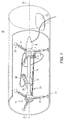
- the main features of the machine 10 include the following design features as shown in Fig. 1. All components are double sealed against the ingress of blasting grit and profiling hardened particles. Sealing is accomplished by double lip seals backed up with felt seals on all rotating surfaces where grit penetration could jam or wear the components.
- the outer surfaces of the two tripod assemblies and 2 and 4, axial motor 6, rotation motor 8, and moveable axial carriage 12 are coated with polyurethane. Tests have shown that the sand and hardened grit simply bounce off the polyurethane thereby completely protecting the aluminum directly underneath the polyurethane.
- the machine is supported on two adjustable tripod assemblies which are directly adjustable to work in a pipe 14 from 32 to about 48 inches (81 to about 123 cm), and beyond, inside diameter.
- a rubber bellows (not shown in Fig. 1) can be used to fit over each tripod leg and prevent the entry of grit into the telescoping legs.
- the center support bar 16 can be a 2.5-inch (6.35 cm) square 0.105-inch (0.26 cm) wall steel tube which can be assembled in any convenient incremental lengths from up to 10 foot (254 cm) long sections typically 5 to 10 foot (152 to 254 cm) sections, which rigidly snap together to form a smooth centered shaft.
- the six tripod legs 18 have adjustable levelers 20 so that the square tube can be aligned concentric with the centerline 22-22 of the pipe 14.
- the square tube slides into the left tripod support and is held in axial position by a shaft clamp.
- the center of the tripod rotates on Kaydon slim-line bearings which permit full 360-degree rotation of the center shaft.
- the Kaydon bearings are pre-loaded against each other to eliminate play and backlash.
- the right tripod support 2 is similar to the left in construction except that it also supports the rotation and axial position motors 8 and 6 respectively. Both of these motors are Compumotor Microstepping motors. Each has 10,000 steps per revolution, which means that all motion factors such as speed, acceleration, peak velocity, and reverse times can be totally and accurately controlled via a programmable controller. This is very important from the standpoint of consistent, repeatable thermal spray coating application. Each motor couples directly to a gearbox to increase torque and generate the optimum spray rate. The axial position gearbox ratio is 50:1 which translates into up to 9 inches (22.8 cm) per second of axial travel.
- the rotation axis uses a harmonic drive gearbox with zero backlash (160:1) ratio resulting in tangential speeds of up to 3 ft. (91 cm) per second.
- the harmonic gear reducer contains a flexspline (an elliptical, nonrigid external gear), a circular spline (a round, rigid internal gear),and a wave generator (an elliptical ball bearing assembly).
- the elliptical wave generator input deflects the flexspline to engage teeth at the major axis.
- the flexspline teeth at minor axis are fully disengaged - where most of the relative motion between teeth occurs.
- the flexspline output rotates in opposite direction to input.
- the rigid circular spline is rotationally fixed.
- the teeth on the nonrigid flexspline and the rigid circular spline are in continuous engagement. Since the flexspline has two teeth fewer than the circular spline, one revolution of the input causes relative motion between the flexspline and the circular spline equal to two teeth. With the circular spline rotationally fixed, the flexspline rotates in the opposite direction to the input at a reduction ratio equal to one-half the number of teeth on the flexspline. This relative rotation may be seen by examining the motion of a single flexspline tooth over one-half an input revolution. The tooth is fully engaged when the major axis of the wave generator input is at 0°.
- the axial carriage 12 rides on the chrome plated steel center tube 16.
- the aluminum housing of the carriage which is polyurethane coated to prevent erosion houses eight polyurethane rollers which roll on the square tube. This housing is pulled along the square tube by a friction-type cable, sprocket chain assembly or other similar type drive 24 which was selected due to its ability to continue to operate with all the abrasive particles present. There are no gears or ball screws to jam with grit.
- the axial carriage has felt wipers, shown generally at 26, to knock the grit off the square tube so the polyurethane wheels ride on a grit-free surface.
- Fig. 1 shows the thermal spray gun 28 attached to the arm on the axial carriage. The manway is shown as 29.
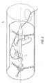
- Fig. 2 shows that if the same arm and drive system operates slowly enough, approximately one inch (2.54 cm) per second peak absolute speed, an abrasion cleaning profiling operation with abrasive grit, using the profiling head 30 can be accomplished.
- the programmable stepper motors can be programmed to move at any desired speed, less than 2.5 cm of arm tip movement per second all the way up to top speeds of 3 feet (91.4 cm) per second.
- the control system for the mechanical delivery apparatus consists of a computer controlled, closed loop motion control, and a video inspection camera, not shown in the figures, for remote viewing of the thermal spray operation.
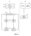
- Fig. 3 shows the block diagram of the control system.
- a 2-axis motion control system is shown as 40 with a display 42, keypad 44 connected in a motion controller 46 which controls motor drives 48 and motor encoders 50.
- a video control 60 contains control 62, video monitor 64 and pan/tilt camera 66.
- the circumferential and axial drives of the thermal spray system both use stepper motors, and the advantage of stepper motors is that they are brushless and will be able to handle the quick changing of direction that is required in the thermal spray operation.
- Each stepper motor has encoders on them that are fed to the motion controller and provide position and speed information.
- the motion controller is the intelligence of the system and has a computer built into it.
- the motion controller has the ability to operate as an embedded system, where as soon as the system is turned on it will automatically run the computer program for that system.
- the motion controller has built-in safety features: it can detect motor stalls, it has over current and over speed trip points, and it can detect an operator emergency stop condition.
- the embedded computer program is stored on battery backed RAM so the program remains even when power is removed from the motion controller.
- the motion controller communicates with the operator through the use of the display and keypad. Through this interface the operator will set up the system parameters depending on whether the system is blasting, profiling or thermal spraying the pipe.
- an additional feature of the control system is the use of a visual system for remotely observing the mechanical system during operation.
- the remote visual system is needed because the operator of the control system is outside of the pipe and during operation will not be able to directly observe the tool. If any part of the operation is malfunctioning it is important for the operator to quickly stop the operation of the tool.
- the visual system consists of a color CCD camera that has a remote focus, auto iris, and zooming capabilities and is mounted in a protective housing.
- the camera can also mount on a platform that can pan and tilt the camera.
- the controls for the camera and the pan/tilt units are mounted in the control system housing which also contains the video monitor.
- the hardware for the motion control and video systems are mounted in a portable enclosure that can be moved around to the proper viewing location.
Landscapes
- Engineering & Computer Science (AREA)
- Chemical & Material Sciences (AREA)
- Mechanical Engineering (AREA)
- Physics & Mathematics (AREA)
- Plasma & Fusion (AREA)
- Chemical Kinetics & Catalysis (AREA)
- Materials Engineering (AREA)
- Metallurgy (AREA)
- Organic Chemistry (AREA)
- Coating By Spraying Or Casting (AREA)
- Spray Control Apparatus (AREA)
Claims (14)
- Maschine (10) zur Beschichtung der Innenfläche eines hohlen, axial lang gestreckten Rohrs (14), die umfasst:(a) einen mittleren Bereich von mindestens einer Führungsstange (16), die konzentrisch mit der Mittellinie (22) des Rohrs (14) ausgerichtet werden kann;(b) mindestens zwei Dreibeine mit mindestens drei Auslegern (18), die das Rohrinnere berühren und den mittleren Bereich der Führungsstange (16) halten;(c) eine Quelle für thermisch spritzbares Material;dadurch gekennzeichnet, dass:der mittlere Bereich der Führungsstange um die eigene Achse drehbar ist;mindestens ein Schlitten (12) bereitgestellt wird, der auf dem mittleren Bereich der Führungsstange montiert ist, so dass er entlang der Länge der Führungsstange beweglich ist, jedoch drehbar mit der Führungsstange verbunden ist, wobei besagter Schlitten mindestens eine Vorrichtung (28) zur Beschichtung mittels thermischen Spritzens trägt, die vom Schlitten zur Innenseite des Rohrs ragt;ein erster Motor (6) bereitgestellt wird, um den Schlitten axial entlang der Führungsstange anzutreiben, und ein zweiter Motor (8) bereitgestellt wird, um den mittleren Bereich der Führungsstange um die eigene Achse zu drehen; und dadurch, dasseine programmierbare Steuerung (40) außerhalb des Rohrs bereitgestellt wird, die in der Lage ist, die Motoren und die Vorrichtung zur Beschichtung mittels thermischen Spritzens zu steuern.
- Maschine nach Anspruch 1, wobei die Dreibeine jeweils ein Lager umfassen, wodurch eine volle 360-Grad-Drehung der zentrischen Welle ermöglicht wird.
- Maschine nach Anspruch 1 oder 2, wobei der mittlere Bereich der zentrischen Welle ein Rohr 16 mit quadratischem Querschnitt umfasst.
- Maschine nach einem der vorhergehenden Ansprüche, wobei alle innen befindlichen Bauteile der Beschichtungsmaschine jedes für sich mit einem abrasionsbeständigen Kunststoffmaterial beschichtet sind.
- Maschine nach einem der vorhergehenden Ansprüche, wobei der bewegliche Schlitten (12) ferner einen Kopf (30) zur Reinigung durch Abrasion mit einem Schleifmedium bzw. zur Oberflächenfeinung umfasst.
- Maschine nach einem der vorhergehenden Ansprüche, wobei alle innen befindlichen Bauteile mit abrasionsbeständigem Polyurethanmaterial beschichtet sind.
- Maschine nach einem der vorhergehenden Ansprüche, wobei die Ausleger des Dreibeins Teleskopausleger sind, die mit Gummi überdeckt sind, und wobei beide Motoren (6, 8) bürstenlose Mikroschrittmotoren sind.
- Maschine nach einem der vorhergehenden Ansprüche, wobei der Schlitten (12) mittels eines Reibriemenantriebs entlang der Führungsstange (16) bewegt wird.
- Maschine nach einem der Ansprüche 1-7, wobei der Schlitten mittels einer Gelenkketten-Baugruppe entlang der Führungsstange bewegt wird.
- Maschine nach einem der vorhergehenden Ansprüche, die ferner eine Videoüberwachungskamera umfasst.
- Maschine nach einem der vorhergehenden Ansprüche, wobei die Vorrichtung (28) zum thermischen Spritzen eine Vorrichtung zum Beschichten mittels Lichtbogenspritzens ist.
- Maschine nach einem der vorhergehenden Ansprüche, die im Inneren eines Rohrs (14) betrieben wird, um eine Beschichtung auf die Rohrinnenseite durch thermisches Spritzen aufzubringen, wobei die Vorrichtung (28) zum Beschichten mittels thermischen Spritzens schrittweise anpassbar ist.
- Verfahren zum Beschichten der Innenfläche eines hohlen, axial lang gestreckten Rohrs (14) mittels einer Maschine (10) nach einem der vorhergehenden Ansprüche,
wobei das Verfahren folgende Schritte umfasst:(1) Antreiben des Schlittens; und(2) Steuern der Vorrichtung zum Beschichten mittels thermischen Spritzens, das von der Steuerung gesteuert wird, um dadurch die Innenfläche zu beschichten. - Verfahren nach Anspruch 13, das ferner den Schritt des Programmierens der programmierbaren Steuerung umfasst.
Applications Claiming Priority (2)
| Application Number | Priority Date | Filing Date | Title |
|---|---|---|---|
| US821974 | 2001-03-30 | ||
| US09/821,974 US6508413B2 (en) | 2000-04-06 | 2001-03-30 | Remote spray coating of nuclear cross-under piping |
Publications (3)
| Publication Number | Publication Date |
|---|---|
| EP1245692A2 EP1245692A2 (de) | 2002-10-02 |
| EP1245692A3 EP1245692A3 (de) | 2004-02-04 |
| EP1245692B1 true EP1245692B1 (de) | 2006-11-29 |
Family
ID=25234754
Family Applications (1)
| Application Number | Title | Priority Date | Filing Date |
|---|---|---|---|
| EP01203080A Expired - Lifetime EP1245692B1 (de) | 2001-03-30 | 2001-08-13 | Fernbediente Sprühbeschichtung von Abdampfrohrleitungen in der Kernindustrie |
Country Status (3)
| Country | Link |
|---|---|
| US (1) | US6508413B2 (de) |
| EP (1) | EP1245692B1 (de) |
| DE (1) | DE60124858T2 (de) |
Cited By (1)
| Publication number | Priority date | Publication date | Assignee | Title |
|---|---|---|---|---|
| WO2017215947A1 (fr) | 2016-06-13 | 2017-12-21 | Battakarst | Cloche de projection de grenaille et d'aspiration de la grenaille projetee, robot pour la renovation de conduites forcees, muni d'une telle cloche |
Families Citing this family (67)
| Publication number | Priority date | Publication date | Assignee | Title |
|---|---|---|---|---|
| GB0312999D0 (en) * | 2003-06-06 | 2003-07-09 | Breval Technical Services Ltd | Conduit inspection apparatus and method |
| US7042184B2 (en) | 2003-07-08 | 2006-05-09 | Board Of Regents Of The University Of Nebraska | Microrobot for surgical applications |
| US7126303B2 (en) * | 2003-07-08 | 2006-10-24 | Board Of Regents Of The University Of Nebraska | Robot for surgical applications |
| US7960935B2 (en) | 2003-07-08 | 2011-06-14 | The Board Of Regents Of The University Of Nebraska | Robotic devices with agent delivery components and related methods |
| US20080058989A1 (en) * | 2006-04-13 | 2008-03-06 | Board Of Regents Of The University Of Nebraska | Surgical camera robot |
| KR100662341B1 (ko) * | 2004-07-09 | 2007-01-02 | 엘지전자 주식회사 | 디스플레이 장치 및 그의 색 재현 방법 |
| US7181985B2 (en) | 2005-05-27 | 2007-02-27 | Breval Technical Services Limited | Conduit inspection apparatus and method |
| US20060283981A1 (en) * | 2005-06-16 | 2006-12-21 | Mead William T | Spray coating nozzle assembly for coating remote areas |
| JP2007050469A (ja) * | 2005-08-17 | 2007-03-01 | Hitachi Plant Technologies Ltd | ブラスト装置及びブラスト方法 |
| US9579088B2 (en) * | 2007-02-20 | 2017-02-28 | Board Of Regents Of The University Of Nebraska | Methods, systems, and devices for surgical visualization and device manipulation |
| US8679096B2 (en) * | 2007-06-21 | 2014-03-25 | Board Of Regents Of The University Of Nebraska | Multifunctional operational component for robotic devices |
| CA3068216C (en) * | 2006-06-22 | 2023-03-07 | Board Of Regents Of The University Of Nebraska | Magnetically coupleable robotic devices and related methods |
| US20080001005A1 (en) * | 2006-07-02 | 2008-01-03 | Lance Weaver | Apparatus for evenly applying liquids to interior surfaces |
| EP3078344B1 (de) | 2007-07-12 | 2020-02-26 | Board of Regents of the University of Nebraska | Betätigung in robotischen vorrichtungen |
| EP2178456B1 (de) * | 2007-08-15 | 2018-10-31 | Board of Regents of the University of Nebraska | Modulare und kooperative medizinische system |
| JP2010536435A (ja) | 2007-08-15 | 2010-12-02 | ボード オブ リージェンツ オブ ザ ユニバーシティ オブ ネブラスカ | 医療用膨張、取り付けおよび送達装置、ならびに関連する方法 |
| US7971497B2 (en) * | 2007-11-26 | 2011-07-05 | Air Products And Chemicals, Inc. | Devices and methods for performing inspections, repairs, and/or other operations within vessels |
| US20100012751A1 (en) * | 2008-07-16 | 2010-01-21 | Warren Marc R | Laser Assisted Aiming System for Fluid Nozzles |
| US9114458B2 (en) | 2009-08-21 | 2015-08-25 | Illinois Tool Works Inc. | Pipe end machining device with axial autofeed |
| WO2011054977A1 (es) | 2009-11-04 | 2011-05-12 | Ingeniería Y Marketing, S.A. | Método y dispositivo para la regeneración de superficies interiores de conductos mediante proyección térmica de metales |
| EP2512754A4 (de) * | 2009-12-17 | 2016-11-30 | Univ Nebraska | Modulare und kooperative medizinische vorrichtungen sowie entsprechende systeme und verfahren |
| CA2804176A1 (en) | 2010-08-06 | 2013-02-05 | Board Of Regents Of The University Of Nebraska | Methods and systems for handling or delivering materials for natural orifice surgery |
| FR2973096B1 (fr) | 2011-03-23 | 2013-04-26 | Entpr Philippe Lassarat | Systeme d'entretien de la paroi interieure d'une conduite et procede de mise en oeuvre |
| EP2717796B1 (de) | 2011-06-10 | 2020-02-26 | Board of Regents of the University of Nebraska | In vivo gefässabdichtender endeffektor |
| EP2732344B1 (de) | 2011-07-11 | 2019-06-05 | Board of Regents of the University of Nebraska | Robotisches chirurgisches system |
| US8800396B2 (en) | 2011-07-14 | 2014-08-12 | Crts, Inc. | Pipeline internal field joint cleaning, coating, and inspection robot |
| EP3730031A1 (de) | 2011-10-03 | 2020-10-28 | Board of Regents of the University of Nebraska | Robotische chirurgische vorrichtungen und systeme |
| WO2013106569A2 (en) | 2012-01-10 | 2013-07-18 | Board Of Regents Of The University Of Nebraska | Methods, systems, and devices for surgical access and insertion |
| EP2844181B1 (de) | 2012-05-01 | 2021-03-10 | Board of Regents of the University of Nebraska | Robotische einzelstandortvorrichtung sowie entsprechende systeme |
| US9010214B2 (en) | 2012-06-22 | 2015-04-21 | Board Of Regents Of The University Of Nebraska | Local control robotic surgical devices and related methods |
| CA2880622C (en) | 2012-08-08 | 2021-01-12 | Board Of Regents Of The University Of Nebraska | Robotic surgical devices, systems and related methods |
| US9770305B2 (en) | 2012-08-08 | 2017-09-26 | Board Of Regents Of The University Of Nebraska | Robotic surgical devices, systems, and related methods |
| US12295680B2 (en) | 2012-08-08 | 2025-05-13 | Board Of Regents Of The University Of Nebraska | Robotic surgical devices, systems and related methods |
| US20140196662A1 (en) * | 2012-12-21 | 2014-07-17 | Fluor Technologies Corporation | Nanoclad Pipe Weld Repair, Systems and Methods |
| CA2906672C (en) | 2013-03-14 | 2022-03-15 | Board Of Regents Of The University Of Nebraska | Methods, systems, and devices relating to force control surgical systems |
| US9743987B2 (en) | 2013-03-14 | 2017-08-29 | Board Of Regents Of The University Of Nebraska | Methods, systems, and devices relating to robotic surgical devices, end effectors, and controllers |
| CA2906772C (en) | 2013-03-15 | 2021-09-21 | Board Of Regents Of The University Of Nebraska | Robotic surgical devices, systems and related methods |
| CA2918531A1 (en) | 2013-07-17 | 2015-01-22 | Board Of Regents Of The University Of Nebraska | Robotic surgical devices, systems and related methods |
| MX370557B (es) | 2013-10-03 | 2019-12-17 | Illinois Tool Works | Soporte de herramientas giratorio para un aparato de maquinado de tubos. |
| WO2015052353A1 (es) | 2013-10-07 | 2015-04-16 | Ingenieria Y Marketing, S.A. | Método y dispositivo para la inspección y regeneración de conductos |
| DE102013223688A1 (de) * | 2013-11-20 | 2015-05-21 | Siemens Aktiengesellschaft | Verfahren und Vorrichtung zum automatisierten Aufbringen einer Spritzbeschichtung |
| US20150197840A1 (en) * | 2014-01-10 | 2015-07-16 | United Technologies Corporation | Systems and methods for removing overspray |
| WO2015197570A1 (de) * | 2014-06-25 | 2015-12-30 | Siemens Aktiengesellschaft | Vorrichtung zur radialen abstützung und dämpfung eines stabförmigen bauteils in einem hohlraum und verfahren zur montage der vorrichtung |
| EP3191009B1 (de) | 2014-09-12 | 2021-03-31 | Board of Regents of the University of Nebraska | Schnelllösbare endeffektoren sowie entsprechende systeme |
| WO2016077478A1 (en) | 2014-11-11 | 2016-05-19 | Board Of Regents Of The University Of Nebraska | Robotic device with compact joint design and related systems and methods |
| CN108472030B (zh) | 2015-08-03 | 2021-06-18 | 内布拉斯加大学董事会 | 机器人手术装置系统及相关方法 |
| GB2545223A (en) * | 2015-12-09 | 2017-06-14 | Rtl Mat Ltd | Apparatus and methods for joining in a tube |
| US10751136B2 (en) | 2016-05-18 | 2020-08-25 | Virtual Incision Corporation | Robotic surgical devices, systems and related methods |
| CN110248614B (zh) | 2016-08-25 | 2023-04-18 | 内布拉斯加大学董事会 | 快速释放工具耦接器以及相关系统和方法 |
| WO2018045036A1 (en) | 2016-08-30 | 2018-03-08 | Board Of Regents Of The University Of Nebraska | Robotic device with compact joint design and an additional degree of freedom and related systems and methods |
| CN106540831B (zh) * | 2016-11-07 | 2018-11-30 | 江苏龙冶节能科技有限公司 | 一种焦炉荒煤气上升管纳米自洁涂料的均匀喷涂装置 |
| WO2018098319A1 (en) | 2016-11-22 | 2018-05-31 | Board Of Regents Of The University Of Nebraska | Improved gross positioning device and related systems and methods |
| WO2018102430A1 (en) | 2016-11-29 | 2018-06-07 | Virtual Incision Corporation | User controller with user presence detection and related systems and methods |
| WO2018112199A1 (en) | 2016-12-14 | 2018-06-21 | Virtual Incision Corporation | Releasable attachment device for coupling to medical devices and related systems and methods |
| CN106670030B (zh) * | 2016-12-25 | 2018-10-19 | 重庆市永川区泰兴机械厂 | 管道内壁喷涂装置 |
| EP3687370B1 (de) | 2017-09-27 | 2024-11-20 | Virtual Incision Corporation | Robotische chirurgische vorrichtungen mit verfolgungskameratechnologie und verwandte systeme |
| WO2019136360A1 (en) | 2018-01-05 | 2019-07-11 | Board Of Regents Of The University Of Nebraska | Single-arm robotic device with compact joint design and related systems and methods |
| GB201806071D0 (en) | 2018-04-13 | 2018-05-30 | Rolls Royce Power Eng Plc | Apparatus |
| CN114302665B (zh) | 2019-01-07 | 2025-12-19 | 虚拟切割有限公司 | 机器人辅助手术系统以及相关装置和方法 |
| CN110216033A (zh) * | 2019-05-29 | 2019-09-10 | 江苏吉鑫风能科技股份有限公司 | 一种细长内孔工件喷涂施工装置及应用其的喷涂方法 |
| CN110258733B (zh) * | 2019-06-13 | 2021-02-02 | 云数势能科技(深圳)有限公司 | 一种自动化的管道清洁装置 |
| CN111136072A (zh) * | 2020-01-12 | 2020-05-12 | 景高平 | 一种新型管道清淤设备 |
| JP2023532977A (ja) | 2020-07-06 | 2023-08-01 | バーチャル インシジョン コーポレイション | 外科用ロボット位置決めシステム並びに関連する装置及び方法 |
| CN113499901B (zh) * | 2021-06-09 | 2022-05-24 | 浙江乐歌智能驱动科技有限公司 | 管内壁喷涂润滑脂的设备 |
| KR102502764B1 (ko) * | 2021-07-16 | 2023-02-23 | 주식회사 에스엠뿌레 | 분무기 노즐 어셈블리 |
| CN115382708B (zh) * | 2022-09-29 | 2023-06-02 | 广东华晟安全职业评价有限公司 | 一种油气运输管道防腐喷涂装置 |
| CN115627437B (zh) * | 2022-11-02 | 2024-05-24 | 中国石油大学(华东) | 一种在小直径管道内表面制备金属涂层的装置 |
Family Cites Families (20)
| Publication number | Priority date | Publication date | Assignee | Title |
|---|---|---|---|---|
| US3071107A (en) * | 1960-09-29 | 1963-01-01 | Richard C Stanley | Pipe coating apparatus |
| NL290528A (de) * | 1962-10-10 | |||
| US3839618A (en) | 1972-01-03 | 1974-10-01 | Geotel Inc | Method and apparatus for effecting high-energy dynamic coating of substrates |
| US3960644A (en) * | 1974-09-25 | 1976-06-01 | Mcfadden Eldon C | Pipe lining apparatus |
| US4036173A (en) * | 1975-07-21 | 1977-07-19 | Nicklas Manfred E | Internal coating and sandblasting bug for pipe |
| DE7722908U1 (de) * | 1977-07-22 | 1977-11-24 | Castolin Gmbh, 6000 Frankfurt | Vorrichtung zur automatischen Auftragsschweißung |
| US4164325A (en) * | 1977-11-21 | 1979-08-14 | Watson John D | High-pressure-rotary-nozzle apparatus |
| US4337723A (en) * | 1980-12-15 | 1982-07-06 | Davis J C | Pipe interior surface coating device |
| JPH065155B2 (ja) | 1984-10-12 | 1994-01-19 | 住友金属工業株式会社 | 窯炉の炉壁補修装置 |
| JPS61186466A (ja) * | 1985-02-15 | 1986-08-20 | Purazumeito:Kk | 管状構造体内壁のプラズマ溶射法 |
| US4869936A (en) * | 1987-12-28 | 1989-09-26 | Amoco Corporation | Apparatus and process for producing high density thermal spray coatings |
| GB9202088D0 (en) * | 1992-01-31 | 1992-03-18 | Thomas Robert E | The manufacture of cylindrical components by centrifugal force |
| DE4240991A1 (de) | 1992-12-05 | 1994-06-09 | Plasma Technik Ag | Plasmaspritzgerät |
| CA2119430A1 (en) * | 1993-04-20 | 1994-10-21 | Joseph P. Mercurio | Dense oxide coatings by thermal spraying |
| US5837959A (en) | 1995-09-28 | 1998-11-17 | Sulzer Metco (Us) Inc. | Single cathode plasma gun with powder feed along central axis of exit barrel |
| US5796064A (en) * | 1996-10-29 | 1998-08-18 | Ingersoll-Rand Company | Method and apparatus for dual coat thermal spraying cylindrical bores |
| US5829461A (en) * | 1997-01-10 | 1998-11-03 | Ramsey; Donald | Interior tank cleaning apparatus |
| US5913977A (en) * | 1998-03-25 | 1999-06-22 | Neuco, Inc. | Apparatus and method for internally coating live gas pipe joints or other discontinuities |
| US6051803A (en) | 1998-08-11 | 2000-04-18 | Hale, Jr.; Dorr E. | Pipe cutting apparatus |
| US6171398B1 (en) | 1999-04-12 | 2001-01-09 | Donald W. Hannu | Apparatus for coating a conduit surface |
-
2001
- 2001-03-30 US US09/821,974 patent/US6508413B2/en not_active Expired - Lifetime
- 2001-08-13 EP EP01203080A patent/EP1245692B1/de not_active Expired - Lifetime
- 2001-08-13 DE DE60124858T patent/DE60124858T2/de not_active Expired - Lifetime
Cited By (1)
| Publication number | Priority date | Publication date | Assignee | Title |
|---|---|---|---|---|
| WO2017215947A1 (fr) | 2016-06-13 | 2017-12-21 | Battakarst | Cloche de projection de grenaille et d'aspiration de la grenaille projetee, robot pour la renovation de conduites forcees, muni d'une telle cloche |
Also Published As
| Publication number | Publication date |
|---|---|
| US6508413B2 (en) | 2003-01-21 |
| US20020003173A1 (en) | 2002-01-10 |
| DE60124858T2 (de) | 2007-05-31 |
| DE60124858D1 (de) | 2007-01-11 |
| EP1245692A3 (de) | 2004-02-04 |
| EP1245692A2 (de) | 2002-10-02 |
Similar Documents
| Publication | Publication Date | Title |
|---|---|---|
| US6508413B2 (en) | Remote spray coating of nuclear cross-under piping | |
| CN112642631B (zh) | 一种用于化工管道外层防腐涂料的喷涂装置 | |
| US10864640B1 (en) | Articulating arm programmable tank cleaning nozzle | |
| US4690159A (en) | Rotary cleaning device | |
| EP2139621B1 (de) | Reinigungsvorrichtung für rohre mit grossem durchmesser | |
| CN109176321B (zh) | 喷砂设备、喷砂系统及喷砂方法 | |
| KR101429935B1 (ko) | 블라스트 가공 장치에 있어서의 블라스트 건의 운동 기구 | |
| EP0007557A1 (de) | Dekontaminierungsvorrichtung zur Dekontaminierung der Deckelkammern von nuklearen Dampferzeugern | |
| US7059945B2 (en) | Pipe weld cleaning machine | |
| JPS60179169A (ja) | 管内面塗装装置 | |
| KR100464462B1 (ko) | 진공흡착식 블라스팅 장치 | |
| JP5538508B2 (ja) | 塗膜延命用スチーム洗浄機 | |
| JP2004016925A (ja) | 管内面ライニング装置 | |
| CN116334523A (zh) | 一种防滑粉末涂料喷涂工艺 | |
| CN106737622B (zh) | 喷砂机器人 | |
| JP2645312B2 (ja) | 双ガンによるサイクロイド吹付方法及び装置 | |
| CN119634130A (zh) | 支承装置、核电站贯穿件套管打磨喷漆装置及其方法 | |
| CN119098318A (zh) | 一种智能制冷喷涂设备 | |
| US9827650B2 (en) | Surface media blaster | |
| CN215744378U (zh) | 闸门面板喷涂装置 | |
| JP2004338071A (ja) | 産業用ロボットの中空手首および産業用ロボット | |
| JP2592989B2 (ja) | 管内作業装置 | |
| US11745309B1 (en) | Remotely operated abrasive blasting apparatus, system, and method | |
| JP7687886B2 (ja) | 噴射装置および洗浄除去方法 | |
| JPH0346866Y2 (de) |
Legal Events
| Date | Code | Title | Description |
|---|---|---|---|
| PUAI | Public reference made under article 153(3) epc to a published international application that has entered the european phase |
Free format text: ORIGINAL CODE: 0009012 |
|
| AK | Designated contracting states |
Kind code of ref document: A2 Designated state(s): AT BE CH CY DE DK ES FI FR GB GR IE IT LI LU MC NL PT SE TR |
|
| AX | Request for extension of the european patent |
Free format text: AL;LT;LV;MK;RO;SI |
|
| PUAL | Search report despatched |
Free format text: ORIGINAL CODE: 0009013 |
|
| AK | Designated contracting states |
Kind code of ref document: A3 Designated state(s): AT BE CH CY DE DK ES FI FR GB GR IE IT LI LU MC NL PT SE TR |
|
| AX | Request for extension of the european patent |
Extension state: AL LT LV MK RO SI |
|
| 17P | Request for examination filed |
Effective date: 20040113 |
|
| 17Q | First examination report despatched |
Effective date: 20040826 |
|
| AKX | Designation fees paid |
Designated state(s): DE FR GB IT |
|
| RAP1 | Party data changed (applicant data changed or rights of an application transferred) |
Owner name: SIEMENS POWER GENERATION, INC. |
|
| GRAP | Despatch of communication of intention to grant a patent |
Free format text: ORIGINAL CODE: EPIDOSNIGR1 |
|
| GRAS | Grant fee paid |
Free format text: ORIGINAL CODE: EPIDOSNIGR3 |
|
| GRAA | (expected) grant |
Free format text: ORIGINAL CODE: 0009210 |
|
| AK | Designated contracting states |
Kind code of ref document: B1 Designated state(s): DE FR GB IT |
|
| REG | Reference to a national code |
Ref country code: GB Ref legal event code: FG4D |
|
| REF | Corresponds to: |
Ref document number: 60124858 Country of ref document: DE Date of ref document: 20070111 Kind code of ref document: P |
|
| ET | Fr: translation filed | ||
| PLBE | No opposition filed within time limit |
Free format text: ORIGINAL CODE: 0009261 |
|
| STAA | Information on the status of an ep patent application or granted ep patent |
Free format text: STATUS: NO OPPOSITION FILED WITHIN TIME LIMIT |
|
| 26N | No opposition filed |
Effective date: 20070830 |
|
| REG | Reference to a national code |
Ref country code: DE Ref legal event code: R081 Ref document number: 60124858 Country of ref document: DE Owner name: SIEMENS ENERGY, INC.(N.D. GES.D. STAATES DELAW, US Free format text: FORMER OWNER: SIEMENS POWER GENERATION, INC., ORLANDO, FLA., US Effective date: 20110516 |
|
| REG | Reference to a national code |
Ref country code: FR Ref legal event code: CD Owner name: SIEMENS ENERGY, INC. Effective date: 20120413 |
|
| PGFP | Annual fee paid to national office [announced via postgrant information from national office to epo] |
Ref country code: FR Payment date: 20140812 Year of fee payment: 14 Ref country code: GB Payment date: 20140815 Year of fee payment: 14 |
|
| PGFP | Annual fee paid to national office [announced via postgrant information from national office to epo] |
Ref country code: IT Payment date: 20140826 Year of fee payment: 14 |
|
| GBPC | Gb: european patent ceased through non-payment of renewal fee |
Effective date: 20150813 |
|
| PG25 | Lapsed in a contracting state [announced via postgrant information from national office to epo] |
Ref country code: IT Free format text: LAPSE BECAUSE OF NON-PAYMENT OF DUE FEES Effective date: 20150813 |
|
| REG | Reference to a national code |
Ref country code: FR Ref legal event code: ST Effective date: 20160429 |
|
| PG25 | Lapsed in a contracting state [announced via postgrant information from national office to epo] |
Ref country code: GB Free format text: LAPSE BECAUSE OF NON-PAYMENT OF DUE FEES Effective date: 20150813 |
|
| PG25 | Lapsed in a contracting state [announced via postgrant information from national office to epo] |
Ref country code: FR Free format text: LAPSE BECAUSE OF NON-PAYMENT OF DUE FEES Effective date: 20150831 |
|
| PGFP | Annual fee paid to national office [announced via postgrant information from national office to epo] |
Ref country code: DE Payment date: 20161020 Year of fee payment: 16 |
|
| REG | Reference to a national code |
Ref country code: DE Ref legal event code: R119 Ref document number: 60124858 Country of ref document: DE |
|
| PG25 | Lapsed in a contracting state [announced via postgrant information from national office to epo] |
Ref country code: DE Free format text: LAPSE BECAUSE OF NON-PAYMENT OF DUE FEES Effective date: 20180301 |