EP1245460A2 - Système de protection de tonneau pour véhicules à moteur avec actuateur pyrotechnique - Google Patents
Système de protection de tonneau pour véhicules à moteur avec actuateur pyrotechnique Download PDFInfo
- Publication number
- EP1245460A2 EP1245460A2 EP02002822A EP02002822A EP1245460A2 EP 1245460 A2 EP1245460 A2 EP 1245460A2 EP 02002822 A EP02002822 A EP 02002822A EP 02002822 A EP02002822 A EP 02002822A EP 1245460 A2 EP1245460 A2 EP 1245460A2
- Authority
- EP
- European Patent Office
- Prior art keywords
- holding
- spring
- protection system
- rollover protection
- rollover
- Prior art date
- Legal status (The legal status is an assumption and is not a legal conclusion. Google has not performed a legal analysis and makes no representation as to the accuracy of the status listed.)
- Granted
Links
Images


Classifications
-
- B—PERFORMING OPERATIONS; TRANSPORTING
- B60—VEHICLES IN GENERAL
- B60R—VEHICLES, VEHICLE FITTINGS, OR VEHICLE PARTS, NOT OTHERWISE PROVIDED FOR
- B60R21/00—Arrangements or fittings on vehicles for protecting or preventing injuries to occupants or pedestrians in case of accidents or other traffic risks
- B60R21/02—Occupant safety arrangements or fittings, e.g. crash pads
- B60R21/13—Roll-over protection
- B60R2021/132—Roll bars for convertible vehicles
- B60R2021/134—Roll bars for convertible vehicles movable from a retracted to a protection position
- B60R2021/135—Roll bars for convertible vehicles movable from a retracted to a protection position automatically during an accident
Definitions
- the invention relates to a rollover protection system for motor vehicles, With a rollover body, which is guided in a vehicle-mounted guide unit is recorded, and in the normal state against the force of at least a biased drive compression spring by a holding device in one lower, retracted rest position is durable, and by loosening the Holding device with a pyrotechnic ejecting a pen Trigger link by the spring force of the drive pressure spring in an upper, there lockable position can be brought.
- Rollover protection systems of this type serve to protect the occupants in Motor vehicles without a protective roof, typically in convertibles or Sports cars.
- these solutions typically have an in a vehicle-fixed cassette housing guided U-shaped or from a Profile body formed roll bar, on, in the normal state against the Preload force of a drive compression spring by a holding device in one lower rest position is maintained, and sensor-controlled in the event of a rollover Loosen the holding device, by the spring force in an upper, protective Position can be brought, which then comes into operative engagement Locking device pressing the roll bar into the cassette prevented.
- the holding device typically has one on the rollover body attached retaining member, which is in releasable mechanical connection with a Trigger element is on a sensor-controlled vehicle-mounted trigger system, typically through a trigger magnet, the so-called Crash magnet, or by a pyrotechnic trigger member is formed.
- DE 43 14 538 C1 shows one so-called, mechanically movably connected to the roll bar Holding rocker as a holding member, which has a holding bolt, which in Operative connection with a hook-shaped trigger member is through Activate the release magnet in a position releasing the retaining bolt is movable.
- the roll bar is triggered in the event of a crash using a pyrotechnic primer is first described in DE 43 42 401 A1 described.
- pyrotechnic Tripping members typically consist of a cartridge with one Ignition charge part, which contains the propellant charge, and a mechanical active part, the contains a pin that can be ejected on ignition and is molded onto a piston, which is a spring-loaded, hook-shaped holding pawl (the holding member on Roll bar), which is detachably accommodated in a vehicle-fixed anchorage is, pushes away and releases from the anchorage.
- the face of the pen is standing after the release essentially in the area of anchoring and therefore prevents the holding member from being re-hooked spatially.
- the invention is based on the object of the type mentioned Rollover protection system for motor vehicles in such a way that also at Holding devices with a pyrotechnic trigger element with simple Reversing the rollover body is possible.
- a particularly simple constructive design of the release system can be achieve according to a development of the invention when the spacer formed by a connecting web of a seesaw bent over the cheeks is, the two bearing bushes for mounting the rocker on the retaining bolt has, wherein the bearing bushes each carry a bias spring, which a connecting bracket comprising the cheeks are connected to one another, such that after a triggering of the connecting bridge from the room underneath the retaining bolt can be pivoted upward around the retaining bolt.
- the vehicle-fixed attachment of the trigger member and the retaining bolt can with advantage in a simple, safe and service-friendly way design that a vehicle-fixed mount is provided with a holder part for the interchangeable holder of the as a cartridge trained pyrotechnic trigger member and a bracket part Bearing blocks for the fixed mounting of the retaining bolt.
- a particularly simple interchangeability of the pyrotechnic trigger element is given when the holding part for the pyrotechnic trigger member is designed as an open clamp holder.
- the undercuts for undercuts have the fixing of the ends of the bias spring.
- the retaining bolt is a safety-critical part of the retaining device according to another embodiment of the retaining bolts using Locking washers fixed in the pedestals.
- a holding device as Proven useful, in which the pawl is hook-shaped angled extension for the active engagement with the retaining bolt having.
- the holding device according to the invention can with different Rollover protection systems find application. Special design advantages are achieved with a rollover protection system with a vehicle-fixed cassette-like housing with side parts, a bottom part and an upper one Guide unit, and a U-shaped roll bar, the two leg tubes possesses, the free ends of which are connected to one another by means of a traverse, by the spring-loaded retaining pawl rotatable on the crossbar is articulated, and both the retaining bolt with the pivotable around it Spacer as well as the pyrotechnic trigger on the bottom part of the cassette are firmly attached.
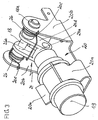
- FIG. 1 shows a perspective view of a Cassette construction of a rollover protection system for motor vehicles, the is each assigned to a vehicle seat in which the inventive Holding device is provided. It is understood that the invention Holding device can also be used in other rollover protection systems can.
- This rollover protection system initially has a U-shaped roll bar 1 on, which is composed of three tubes 2, 3, 4. Thereby forms the Base leg of the roll bar 1 essentially a curved tube 2, which at its ends with two leg tubes 3, 4 by welding or other suitable connection types is rigidly connected.
- a rollover body which consists of a one-piece profile body is formed.
- leg tubes 3, 4 are by means of a cross member 5 rigidly connected to each other.
- the traverse 5 as Profile body formed with a predetermined height
- the holes 6 for Includes the leg tubes 3, 4, in which they are attached.
- the roll bar 1 is with its two leg tubes 3, 4, one Have closed outer surface and the connecting crossmember 5, in a cassette-like housing 7 received and extendable or retractable held in it.
- This housing has two side parts 8, 9 through one U-shaped profile bodies are formed, which are preferably made of metal, in particular made of steel. These side profiles 8, 9 are below a Floor panel part 10 and above via a guide block 11 fixed to the vehicle interconnected, e.g. by riveting, screwing, welding or like.
- two spring guide bolts 12, 13 are anchored, on which Preloadable compression springs (not shown) for extending the Roll bar 1 in the event of danger or when triggered manually, are pushed on and which run the thigh tubes.
- the two side profiles 8, 9 are useful, at least on a front side the cassette, connected to a cover plate that is practical, however not necessarily over the entire height of the cassette (not ) Shown.
- the guide block 11 has two guide bores 14, 15 which the Support lateral surface of the leg tubes 3, 4 laterally and a very wide tolerated guidance for the along the guide holes 14, 15th moving leg tubes 3, 4 offer.
- the curved tube 2 facing end of the guide bores 14, 15 is expediently a radial Countersink or annular groove created, which in a known manner receives annular, radially elastic guide bushing (not shown), whereby the radial play of the stirrup leg tubes 3, 4 in the Guide holes 14, 15 is compensated.
- the Leg tubes also provided an inner guide, which is mentioned by the housing-fixed spring guide bolts or standpipes is guaranteed.
- a sensor-controlled triggering system in one Bracket 20 firmly attached, preferably by a pin 23rd (Fig. 6) ejecting pyrotechnic trigger element 19 is formed, the the relatively high contact force of the Holding pawl 17 on the holding pin 18 can overcome.
- This pyrotechnic Trigger system will be explained in more detail later.
- the retaining bolt 18 mounted, which is also a shaft for a pivotable Rocker 24 (Fig. 5) represents a cranked over cheeks 24 d
- Has connecting leg 24 a which connecting leg 24 a Rocker between the end of the pin 23 and the end of the nose 17 a the holding pawl 17 lies, i.e. as a movable spacer the space between Pin 23 and retaining bolt 18 bridges.
- a locking pin 21 is attached, which is in the upper Position with a locking pawl, which is also in the traverse 5 to the Shaft 16 is pivotally articulated, can be brought into active engagement in a locking manner, to prevent the roll bar from being pressed into an extended position To prevent position.
- the pin 23 of the pyrotechnic trigger system 19 bumps About the cranked connecting leg 24 a of the rocker 24, the nose 17 a the holding pawl 17 from the active engagement with the holding pin 18 and there thus the roll bar 1 free, which, together with the cross member 5, is driven by the Compression springs, moves to its upper position.
- this installation movement ratchets the locking pawl held in the moving crossbar 5 over the Interlocking of the vehicle-mounted on the guide block 11 Locking pin 21 and locked in the upper position a retraction.
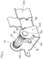
- the bracket 20 for the pyrotechnic trigger system has how FIGS. 2-4 in particular also show a clamping area 20 a for the Detachable holders of the cartridge-like pyrotechnic trigger element 19 and a storage area in the form of bearing blocks 20 b for the retaining bolt 18, which is secured in the bearing blocks by means of locking washers 18 a.
- This bracket 20 is fixedly attached to the bottom part 10 of the cassette, e.g. via rivet connections 25.
- rocker 24 On the retaining bolt 18, that in FIG. 5 is closer shown rocker 24 rotatably supported, the bearing bushes 24 b and the connecting leg 24 a bent over cheeks 24 a and has a lateral actuating pin 24 c.
- part A bridges the connecting leg 24 a in the idle state, the distance between the front face of the pin 23 and the End face of the hook-shaped extension 17 a of the holding pawl 17, i.e. the Connecting leg (or connecting web) 24 a represents a spacer.
- the pin 23 presses it Spacer 24 a explosively against the extension 17 a of the pawl 17th and pivots the rocker 24 around the retaining bolt 18 while removing the Active engagement with the retaining bolt, whereby the retaining pawl 17 is released and with the traverse 5, i.e. the roll bar 1 extends upwards.
- the Pin 23 remains at a sufficient distance in front of the retaining bolt, i.e. he does not block the space below the retaining bolt 18. This condition is in Fig. 6, part B and C shown.
- the rocker 24 is about 270 ° by the biasing force of the spring 26 pivoted clockwise, and lies with the connecting web 24 a, as part C shows the pyrotechnic release 19.
- a new pyrotechnic cartridge 19 is required for activation insert and by manual actuation of the pin 24 c the rocker 24 in the starting position (figure part A) counterclockwise pivot.
Landscapes
- Engineering & Computer Science (AREA)
- Mechanical Engineering (AREA)
- Seats For Vehicles (AREA)
- Air Bags (AREA)
Applications Claiming Priority (2)
| Application Number | Priority Date | Filing Date | Title |
|---|---|---|---|
| DE2001115392 DE10115392C1 (de) | 2001-03-29 | 2001-03-29 | Überrollschutzsystem für Kraftfahrzeuge mit einem pyrotechnischen Aktuator |
| DE10115392 | 2001-03-29 |
Publications (4)
| Publication Number | Publication Date |
|---|---|
| EP1245460A2 true EP1245460A2 (fr) | 2002-10-02 |
| EP1245460A3 EP1245460A3 (fr) | 2004-05-12 |
| EP1245460A9 EP1245460A9 (fr) | 2005-04-13 |
| EP1245460B1 EP1245460B1 (fr) | 2005-08-31 |
Family
ID=7679454
Family Applications (1)
| Application Number | Title | Priority Date | Filing Date |
|---|---|---|---|
| EP20020002822 Expired - Lifetime EP1245460B1 (fr) | 2001-03-29 | 2002-02-08 | Système de protection de tonneau pour véhicules à moteur avec actuateur pyrotechnique |
Country Status (2)
| Country | Link |
|---|---|
| EP (1) | EP1245460B1 (fr) |
| DE (2) | DE10115392C1 (fr) |
Citations (3)
| Publication number | Priority date | Publication date | Assignee | Title |
|---|---|---|---|---|
| EP0657326A1 (fr) * | 1993-12-13 | 1995-06-14 | ITT Automotive Europe GmbH | Arceau de sécurité pour véhicules automobiles |
| DE10027753C1 (de) * | 2000-06-03 | 2001-09-06 | Ise Gmbh | Überrollschutzvorrichtung für Kraftfahrzeuge mit einem pyrotechnischen und einem weiteren, sich bei der Auslösung nicht verbrauchenden Aktuator |
| DE10103245C1 (de) * | 2001-01-25 | 2002-02-21 | Ise Gmbh | Überrollschutzsystem für Kraftfahrzeuge |
Family Cites Families (6)
| Publication number | Priority date | Publication date | Assignee | Title |
|---|---|---|---|---|
| DE3732562C1 (de) * | 1987-09-26 | 1988-11-24 | Daimler Benz Ag | Antriebsvorrichtung fuer einen UEberrollbuegel fuer Kraftwagen |
| DE4314538C3 (de) * | 1993-05-03 | 2000-11-09 | Bayerische Motoren Werke Ag | Überrollschutz-Vorrichtung für ein Kraftfahrzeug |
| DE4342400C2 (de) * | 1993-08-03 | 2002-06-13 | Ise Gmbh | Überrollbügeleinrichtung |
| US5820998A (en) * | 1994-03-08 | 1998-10-13 | Schweitzer-Mauduit International, Inc. | Coated paper and process for making the same |
| DE19531599A1 (de) * | 1995-08-28 | 1997-03-06 | Bayerische Motoren Werke Ag | Kupplung für ein in eine Wirkstellung verlagerbares Sicherheitsteil eines Fahrzeugs, insbesondere für einen Überrollbügel |
| DE19750457C2 (de) * | 1997-11-14 | 2000-08-10 | Ise Gmbh | Ausfahrbarer Überrollbügel für Kraftfahrzeuge |
-
2001
- 2001-03-29 DE DE2001115392 patent/DE10115392C1/de not_active Expired - Fee Related
-
2002
- 2002-02-08 EP EP20020002822 patent/EP1245460B1/fr not_active Expired - Lifetime
- 2002-02-08 DE DE50204052T patent/DE50204052D1/de not_active Expired - Fee Related
Patent Citations (3)
| Publication number | Priority date | Publication date | Assignee | Title |
|---|---|---|---|---|
| EP0657326A1 (fr) * | 1993-12-13 | 1995-06-14 | ITT Automotive Europe GmbH | Arceau de sécurité pour véhicules automobiles |
| DE10027753C1 (de) * | 2000-06-03 | 2001-09-06 | Ise Gmbh | Überrollschutzvorrichtung für Kraftfahrzeuge mit einem pyrotechnischen und einem weiteren, sich bei der Auslösung nicht verbrauchenden Aktuator |
| DE10103245C1 (de) * | 2001-01-25 | 2002-02-21 | Ise Gmbh | Überrollschutzsystem für Kraftfahrzeuge |
Also Published As
| Publication number | Publication date |
|---|---|
| EP1245460A3 (fr) | 2004-05-12 |
| DE10115392C1 (de) | 2002-06-13 |
| EP1245460B1 (fr) | 2005-08-31 |
| EP1245460A9 (fr) | 2005-04-13 |
| DE50204052D1 (de) | 2005-10-06 |
Similar Documents
| Publication | Publication Date | Title |
|---|---|---|
| DE4345524C2 (de) | Überrollschutzsystem | |
| DE10243497B4 (de) | Vorrichtung zum Schutz von Personen bei einem Frontalaufprall auf ein Kraftfahrzeug | |
| DE4342400A1 (de) | Überrollbügeleinrichtung mit Innenführung und Außenführung | |
| DE10219447A1 (de) | Überrollschutzsystem für Kraftfahrzeuge mit einer selbsthaltenden Entriegelungseinrichtung | |
| EP1288079B1 (fr) | Systéme de protection en cas de retournement d'un véhicle automobile comportant une zone de déformation programmée | |
| EP0916552B1 (fr) | Arceau de sécurité déployable pour véhicules | |
| DE10040649C1 (de) | Überrollschutzsystem | |
| EP1186483B1 (fr) | Cartouche pour arceau de sécurité guidant un arceau déployable et rétractable | |
| EP1095823B1 (fr) | Dispositif de protection contre le retournement pour véhicules | |
| DE10223420C2 (de) | Überrollschutzsystem für Kraftfahrzeuge mit Soll-Deformationsstelle | |
| EP1610985B1 (fr) | Dispositif de protection de personnes en cas de choc frontal avec un vehicule | |
| WO2005044645A1 (fr) | Actionneur pour systeme antichoc d'un vehicule | |
| EP1227011B1 (fr) | Système d'arceau de sécurité pour véhicules automobiles | |
| DE10229635C1 (de) | Überrollschutzsystem für Kraftfahrzeuge | |
| EP1608539A1 (fr) | Dispositif pour proteger des personnes lors d'un choc frontal avec un vehicule | |
| DE10103245C1 (de) | Überrollschutzsystem für Kraftfahrzeuge | |
| DE10115392C1 (de) | Überrollschutzsystem für Kraftfahrzeuge mit einem pyrotechnischen Aktuator | |
| DE10103249C1 (de) | Überrollschutzsystem für Kraftfahrzeuge | |
| DE102004015819B4 (de) | Vorrichtung zum Aufstellen der Fronthaube eines Kraftfahrzeuges zumindest im frontseitigen Haubenschloßbereich bei einem drohenden Personenaufprall mit einer Einrichtung zum Reversieren der aufgestellten Fronthaube | |
| EP1539543A2 (fr) | Systeme de protection en cas de tonneaux pour vehicules automobiles | |
| WO2005005209A1 (fr) | Dispositif servant a proteger des personnes en cas de choc frontal sur un vehicule automobile | |
| WO2005047069A1 (fr) | Dispositif pour inverser le mouvement du capot avant d'un vehicule releve par capteurs pour la protection contre les accidents | |
| DE10327447B3 (de) | Vorrichtung zum Schutz von Personen bei einem Frontalaufprall auf ein Kraftfahrzeug | |
| EP1013513B1 (fr) | Dispositif pour arceau de sécurité pour des véhicules automobiles | |
| DE20215275U1 (de) | Dreiteiliger Überrollbügel |
Legal Events
| Date | Code | Title | Description |
|---|---|---|---|
| PUAI | Public reference made under article 153(3) epc to a published international application that has entered the european phase |
Free format text: ORIGINAL CODE: 0009012 |
|
| AK | Designated contracting states |
Kind code of ref document: A2 Designated state(s): AT BE CH CY DE DK ES FI FR GB GR IE IT LI LU MC NL PT SE TR |
|
| AX | Request for extension of the european patent |
Free format text: AL;LT;LV;MK;RO;SI |
|
| PUAL | Search report despatched |
Free format text: ORIGINAL CODE: 0009013 |
|
| AK | Designated contracting states |
Kind code of ref document: A3 Designated state(s): AT BE CH CY DE DK ES FI FR GB GR IE IT LI LU MC NL PT SE TR |
|
| AX | Request for extension of the european patent |
Extension state: AL LT LV MK RO SI |
|
| 17P | Request for examination filed |
Effective date: 20040804 |
|
| AKX | Designation fees paid |
Designated state(s): DE FR GB IT |
|
| GRAP | Despatch of communication of intention to grant a patent |
Free format text: ORIGINAL CODE: EPIDOSNIGR1 |
|
| GRAS | Grant fee paid |
Free format text: ORIGINAL CODE: EPIDOSNIGR3 |
|
| GRAA | (expected) grant |
Free format text: ORIGINAL CODE: 0009210 |
|
| AK | Designated contracting states |
Kind code of ref document: B1 Designated state(s): DE FR GB IT |
|
| REG | Reference to a national code |
Ref country code: GB Ref legal event code: FG4D Free format text: NOT ENGLISH |
|
| REF | Corresponds to: |
Ref document number: 50204052 Country of ref document: DE Date of ref document: 20051006 Kind code of ref document: P |
|
| GBT | Gb: translation of ep patent filed (gb section 77(6)(a)/1977) |
Effective date: 20051223 |
|
| ET | Fr: translation filed | ||
| PLBE | No opposition filed within time limit |
Free format text: ORIGINAL CODE: 0009261 |
|
| STAA | Information on the status of an ep patent application or granted ep patent |
Free format text: STATUS: NO OPPOSITION FILED WITHIN TIME LIMIT |
|
| 26N | No opposition filed |
Effective date: 20060601 |
|
| PG25 | Lapsed in a contracting state [announced via postgrant information from national office to epo] |
Ref country code: DE Free format text: LAPSE BECAUSE OF NON-PAYMENT OF DUE FEES Effective date: 20060901 |
|
| PGFP | Annual fee paid to national office [announced via postgrant information from national office to epo] |
Ref country code: GB Payment date: 20090223 Year of fee payment: 8 |
|
| PGFP | Annual fee paid to national office [announced via postgrant information from national office to epo] |
Ref country code: IT Payment date: 20090225 Year of fee payment: 8 |
|
| GBPC | Gb: european patent ceased through non-payment of renewal fee |
Effective date: 20100208 |
|
| PG25 | Lapsed in a contracting state [announced via postgrant information from national office to epo] |
Ref country code: IT Free format text: LAPSE BECAUSE OF NON-PAYMENT OF DUE FEES Effective date: 20100208 Ref country code: GB Free format text: LAPSE BECAUSE OF NON-PAYMENT OF DUE FEES Effective date: 20100208 |
|
| PGFP | Annual fee paid to national office [announced via postgrant information from national office to epo] |
Ref country code: FR Payment date: 20140218 Year of fee payment: 13 |
|
| REG | Reference to a national code |
Ref country code: FR Ref legal event code: ST Effective date: 20151030 |
|
| PG25 | Lapsed in a contracting state [announced via postgrant information from national office to epo] |
Ref country code: FR Free format text: LAPSE BECAUSE OF NON-PAYMENT OF DUE FEES Effective date: 20150302 |