EP1245460A2 - Rollover protection system for vehicles with a pyrotechnical actuator - Google Patents
Rollover protection system for vehicles with a pyrotechnical actuator Download PDFInfo
- Publication number
- EP1245460A2 EP1245460A2 EP02002822A EP02002822A EP1245460A2 EP 1245460 A2 EP1245460 A2 EP 1245460A2 EP 02002822 A EP02002822 A EP 02002822A EP 02002822 A EP02002822 A EP 02002822A EP 1245460 A2 EP1245460 A2 EP 1245460A2
- Authority
- EP
- European Patent Office
- Prior art keywords
- holding
- spring
- protection system
- rollover protection
- rollover
- Prior art date
- Legal status (The legal status is an assumption and is not a legal conclusion. Google has not performed a legal analysis and makes no representation as to the accuracy of the status listed.)
- Granted
Links
Images


Classifications
-
- B—PERFORMING OPERATIONS; TRANSPORTING
- B60—VEHICLES IN GENERAL
- B60R—VEHICLES, VEHICLE FITTINGS, OR VEHICLE PARTS, NOT OTHERWISE PROVIDED FOR
- B60R21/00—Arrangements or fittings on vehicles for protecting or preventing injuries to occupants or pedestrians in case of accidents or other traffic risks
- B60R21/02—Occupant safety arrangements or fittings, e.g. crash pads
- B60R21/13—Roll-over protection
- B60R2021/132—Roll bars for convertible vehicles
- B60R2021/134—Roll bars for convertible vehicles movable from a retracted to a protection position
- B60R2021/135—Roll bars for convertible vehicles movable from a retracted to a protection position automatically during an accident
Definitions
- the invention relates to a rollover protection system for motor vehicles, With a rollover body, which is guided in a vehicle-mounted guide unit is recorded, and in the normal state against the force of at least a biased drive compression spring by a holding device in one lower, retracted rest position is durable, and by loosening the Holding device with a pyrotechnic ejecting a pen Trigger link by the spring force of the drive pressure spring in an upper, there lockable position can be brought.
- Rollover protection systems of this type serve to protect the occupants in Motor vehicles without a protective roof, typically in convertibles or Sports cars.
- these solutions typically have an in a vehicle-fixed cassette housing guided U-shaped or from a Profile body formed roll bar, on, in the normal state against the Preload force of a drive compression spring by a holding device in one lower rest position is maintained, and sensor-controlled in the event of a rollover Loosen the holding device, by the spring force in an upper, protective Position can be brought, which then comes into operative engagement Locking device pressing the roll bar into the cassette prevented.
- the holding device typically has one on the rollover body attached retaining member, which is in releasable mechanical connection with a Trigger element is on a sensor-controlled vehicle-mounted trigger system, typically through a trigger magnet, the so-called Crash magnet, or by a pyrotechnic trigger member is formed.
- DE 43 14 538 C1 shows one so-called, mechanically movably connected to the roll bar Holding rocker as a holding member, which has a holding bolt, which in Operative connection with a hook-shaped trigger member is through Activate the release magnet in a position releasing the retaining bolt is movable.
- the roll bar is triggered in the event of a crash using a pyrotechnic primer is first described in DE 43 42 401 A1 described.
- pyrotechnic Tripping members typically consist of a cartridge with one Ignition charge part, which contains the propellant charge, and a mechanical active part, the contains a pin that can be ejected on ignition and is molded onto a piston, which is a spring-loaded, hook-shaped holding pawl (the holding member on Roll bar), which is detachably accommodated in a vehicle-fixed anchorage is, pushes away and releases from the anchorage.
- the face of the pen is standing after the release essentially in the area of anchoring and therefore prevents the holding member from being re-hooked spatially.
- the invention is based on the object of the type mentioned Rollover protection system for motor vehicles in such a way that also at Holding devices with a pyrotechnic trigger element with simple Reversing the rollover body is possible.
- a particularly simple constructive design of the release system can be achieve according to a development of the invention when the spacer formed by a connecting web of a seesaw bent over the cheeks is, the two bearing bushes for mounting the rocker on the retaining bolt has, wherein the bearing bushes each carry a bias spring, which a connecting bracket comprising the cheeks are connected to one another, such that after a triggering of the connecting bridge from the room underneath the retaining bolt can be pivoted upward around the retaining bolt.
- the vehicle-fixed attachment of the trigger member and the retaining bolt can with advantage in a simple, safe and service-friendly way design that a vehicle-fixed mount is provided with a holder part for the interchangeable holder of the as a cartridge trained pyrotechnic trigger member and a bracket part Bearing blocks for the fixed mounting of the retaining bolt.
- a particularly simple interchangeability of the pyrotechnic trigger element is given when the holding part for the pyrotechnic trigger member is designed as an open clamp holder.
- the undercuts for undercuts have the fixing of the ends of the bias spring.
- the retaining bolt is a safety-critical part of the retaining device according to another embodiment of the retaining bolts using Locking washers fixed in the pedestals.
- a holding device as Proven useful, in which the pawl is hook-shaped angled extension for the active engagement with the retaining bolt having.
- the holding device according to the invention can with different Rollover protection systems find application. Special design advantages are achieved with a rollover protection system with a vehicle-fixed cassette-like housing with side parts, a bottom part and an upper one Guide unit, and a U-shaped roll bar, the two leg tubes possesses, the free ends of which are connected to one another by means of a traverse, by the spring-loaded retaining pawl rotatable on the crossbar is articulated, and both the retaining bolt with the pivotable around it Spacer as well as the pyrotechnic trigger on the bottom part of the cassette are firmly attached.
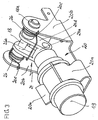
- FIG. 1 shows a perspective view of a Cassette construction of a rollover protection system for motor vehicles, the is each assigned to a vehicle seat in which the inventive Holding device is provided. It is understood that the invention Holding device can also be used in other rollover protection systems can.
- This rollover protection system initially has a U-shaped roll bar 1 on, which is composed of three tubes 2, 3, 4. Thereby forms the Base leg of the roll bar 1 essentially a curved tube 2, which at its ends with two leg tubes 3, 4 by welding or other suitable connection types is rigidly connected.
- a rollover body which consists of a one-piece profile body is formed.
- leg tubes 3, 4 are by means of a cross member 5 rigidly connected to each other.
- the traverse 5 as Profile body formed with a predetermined height
- the holes 6 for Includes the leg tubes 3, 4, in which they are attached.
- the roll bar 1 is with its two leg tubes 3, 4, one Have closed outer surface and the connecting crossmember 5, in a cassette-like housing 7 received and extendable or retractable held in it.
- This housing has two side parts 8, 9 through one U-shaped profile bodies are formed, which are preferably made of metal, in particular made of steel. These side profiles 8, 9 are below a Floor panel part 10 and above via a guide block 11 fixed to the vehicle interconnected, e.g. by riveting, screwing, welding or like.
- two spring guide bolts 12, 13 are anchored, on which Preloadable compression springs (not shown) for extending the Roll bar 1 in the event of danger or when triggered manually, are pushed on and which run the thigh tubes.
- the two side profiles 8, 9 are useful, at least on a front side the cassette, connected to a cover plate that is practical, however not necessarily over the entire height of the cassette (not ) Shown.
- the guide block 11 has two guide bores 14, 15 which the Support lateral surface of the leg tubes 3, 4 laterally and a very wide tolerated guidance for the along the guide holes 14, 15th moving leg tubes 3, 4 offer.
- the curved tube 2 facing end of the guide bores 14, 15 is expediently a radial Countersink or annular groove created, which in a known manner receives annular, radially elastic guide bushing (not shown), whereby the radial play of the stirrup leg tubes 3, 4 in the Guide holes 14, 15 is compensated.
- the Leg tubes also provided an inner guide, which is mentioned by the housing-fixed spring guide bolts or standpipes is guaranteed.
- a sensor-controlled triggering system in one Bracket 20 firmly attached, preferably by a pin 23rd (Fig. 6) ejecting pyrotechnic trigger element 19 is formed, the the relatively high contact force of the Holding pawl 17 on the holding pin 18 can overcome.
- This pyrotechnic Trigger system will be explained in more detail later.
- the retaining bolt 18 mounted, which is also a shaft for a pivotable Rocker 24 (Fig. 5) represents a cranked over cheeks 24 d
- Has connecting leg 24 a which connecting leg 24 a Rocker between the end of the pin 23 and the end of the nose 17 a the holding pawl 17 lies, i.e. as a movable spacer the space between Pin 23 and retaining bolt 18 bridges.
- a locking pin 21 is attached, which is in the upper Position with a locking pawl, which is also in the traverse 5 to the Shaft 16 is pivotally articulated, can be brought into active engagement in a locking manner, to prevent the roll bar from being pressed into an extended position To prevent position.
- the pin 23 of the pyrotechnic trigger system 19 bumps About the cranked connecting leg 24 a of the rocker 24, the nose 17 a the holding pawl 17 from the active engagement with the holding pin 18 and there thus the roll bar 1 free, which, together with the cross member 5, is driven by the Compression springs, moves to its upper position.
- this installation movement ratchets the locking pawl held in the moving crossbar 5 over the Interlocking of the vehicle-mounted on the guide block 11 Locking pin 21 and locked in the upper position a retraction.
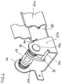
- the bracket 20 for the pyrotechnic trigger system has how FIGS. 2-4 in particular also show a clamping area 20 a for the Detachable holders of the cartridge-like pyrotechnic trigger element 19 and a storage area in the form of bearing blocks 20 b for the retaining bolt 18, which is secured in the bearing blocks by means of locking washers 18 a.
- This bracket 20 is fixedly attached to the bottom part 10 of the cassette, e.g. via rivet connections 25.
- rocker 24 On the retaining bolt 18, that in FIG. 5 is closer shown rocker 24 rotatably supported, the bearing bushes 24 b and the connecting leg 24 a bent over cheeks 24 a and has a lateral actuating pin 24 c.
- part A bridges the connecting leg 24 a in the idle state, the distance between the front face of the pin 23 and the End face of the hook-shaped extension 17 a of the holding pawl 17, i.e. the Connecting leg (or connecting web) 24 a represents a spacer.
- the pin 23 presses it Spacer 24 a explosively against the extension 17 a of the pawl 17th and pivots the rocker 24 around the retaining bolt 18 while removing the Active engagement with the retaining bolt, whereby the retaining pawl 17 is released and with the traverse 5, i.e. the roll bar 1 extends upwards.
- the Pin 23 remains at a sufficient distance in front of the retaining bolt, i.e. he does not block the space below the retaining bolt 18. This condition is in Fig. 6, part B and C shown.
- the rocker 24 is about 270 ° by the biasing force of the spring 26 pivoted clockwise, and lies with the connecting web 24 a, as part C shows the pyrotechnic release 19.
- a new pyrotechnic cartridge 19 is required for activation insert and by manual actuation of the pin 24 c the rocker 24 in the starting position (figure part A) counterclockwise pivot.
Abstract
Derartige Überrollschutzsysteme besitzen typischerweise einen geführten Überrollkörper, der im Normalzustand gegen die Kraft von mindestens einer vorgespannten Antriebs-Druckfeder durch eine Haltevorrichtung in einer unteren, eingefahrenen Ruhelage haltbar ist, und unter Lösen der Haltevorrichtung durch die Federkraft der Antriebs-Druckfeder in eine obere, dort verriegelbare schützende Stellung bringbar ist. Diese Haltevorrichtungen besitzen ferner ein sensorgesteurtes Auslöseglied, das mit zunehmender Tendenz durch ein einen Stift ausstoßendes, pyrotechnisches Auslöseglied gebildet wird. Um ein einfaches Reversieren des Überrollkörpers zu gewährleisten, ist das Überrollschutzsystem so ausgebildet, daß die Haltevorrichtung eine mit dem Überrollkörper (1) drehbeweglich verbundene, federvorgespannte Halteklinke (17) und einen fahrzeugfest angebrachten Haltebolzen (18) aufweist, die in der Ruhelage haltend miteinander in Wirkverbindung stehen, und daß zwischen der Stirnfläche des Stiftes (23) des pyrotechnischen Auslösegliedes (19) und der Halteklinke (17) ein federvorgepanntes, um den Haltebolzen (18) verschwenkbares Distanzstück (24 a) angeordnet ist. <IMAGE>Rollover protection systems of this type typically have a guided rollover body, which in the normal state can be held against the force of at least one pretensioned drive compression spring by a holding device in a lower, retracted rest position, and when the holding device is released by the spring force of the drive compression spring in an upper, there lockable protective position can be brought. These holding devices also have a sensor-controlled trigger element, which is formed with increasing tendency by a pyrotechnic trigger element which ejects a pin. In order to ensure a simple reversal of the rollover body, the rollover protection system is designed so that the holding device has a spring-loaded retaining pawl (17) which is connected to the rollover body (1) so that it can rotate, and a holding bolt (18) which is fixed to the vehicle and which is held together in the rest position Are operatively connected, and that between the end face of the pin (23) of the pyrotechnic trigger member (19) and the holding pawl (17) a spring-biased, around the holding bolt (18) pivotable spacer (24 a) is arranged. <IMAGE>
Description
Die Erfindung bezieht sich auf ein Überrollschutzsystem für Kraftfahrzeuge, mit einem Überrollkörper, der in einer fahrzeugfesten Führungseinheit geführt aufgenommen ist, und der im Normalzustand gegen die Kraft von mindestens einer vorgespannten Antriebs-Druckfeder durch eine Haltevorrichtung in einer unteren, eingefahrenen Ruhelage haltbar ist, und unter Lösen der Haltevorrichtung mit einem einen Stift ausstoßenden pyrotechnischen Auslöseglied durch die Federkraft der Antriebs-Druckfeder in eine obere, dort verriegelbare Stellung bringbar ist.The invention relates to a rollover protection system for motor vehicles, With a rollover body, which is guided in a vehicle-mounted guide unit is recorded, and in the normal state against the force of at least a biased drive compression spring by a holding device in one lower, retracted rest position is durable, and by loosening the Holding device with a pyrotechnic ejecting a pen Trigger link by the spring force of the drive pressure spring in an upper, there lockable position can be brought.
Derartige Überrollschutzsysteme dienen zum Schutz der Insassen in Kraftfahrzeugen ohne schützendes Dach, typischerweise in Cabriolets oder Sportwagen.Rollover protection systems of this type serve to protect the occupants in Motor vehicles without a protective roof, typically in convertibles or Sports cars.
Es ist dabei bekannt, einen die gesamte Fahrzeugbreite überspannenden, fest installierten Überrollbügel vorzusehen oder jedem Fahrzeugsitz einen höhenunveränderlich fest installierten Überrollbügel zuzuordnen.It is known to be a fixed, spanning the entire vehicle width installed roll bar to provide or each vehicle seat to be assigned to fixed roll bars that cannot be changed in height.
Bei beiden Lösungen wird der erhöhte Luftwiderstand und das Auftreten von Fahrgeräuschen als nachteilig empfunden, abgesehen von der Beeinträchtigung des Fahrzeugaussehens. With both solutions, the increased air resistance and the occurrence of Driving noises perceived as disadvantageous, apart from the impairment of vehicle appearance.
Am Markt setzen sich daher immer mehr konstruktive Lösungen durch, bei denen der Überrollbügel im Normalzustand eingefahren ist, und im Gefahrenfall, also bei einem drohenden Überschlag, schnell in eine schützende Position ausgefahren wird, um zu verhindern, daß die Fahrzeuginsassen durch das sich überschlagende Fahrzeug erdrückt werden.Therefore, more and more constructive solutions are gaining acceptance on the market which the roll bar is retracted in the normal state, and in In the event of danger, i.e. in the event of an impending rollover, quickly into a protective Position is extended to prevent the vehicle occupants from going through the overturning vehicle is crushed.
Diese Lösungen weisen typischerweise gemäß der DE 43 42 400 A1 einen in einem fahrzeugfesten Kassetten-Gehäuse geführten U-förmigen oder aus einem Profilkörper gebildeten Überrollbügel, auf, der im Normalzustand gegen die Vorspannkraft einer Antriebs-Druckfeder durch eine Haltevorrichtung in einer unteren Ruhelage gehalten wird, und im Überschlagfall sensorgesteuert unter Lösen der Haltevorrichtung, durch die Federkraft in eine obere, schützende Stellung bringbar ist, wobei eine dann in Wirkeingriff tretende Verriegelungseinrichtung ein Eindrücken des Überrollbügels in die Kassette verhindert.According to DE 43 42 400 A1, these solutions typically have an in a vehicle-fixed cassette housing guided U-shaped or from a Profile body formed roll bar, on, in the normal state against the Preload force of a drive compression spring by a holding device in one lower rest position is maintained, and sensor-controlled in the event of a rollover Loosen the holding device, by the spring force in an upper, protective Position can be brought, which then comes into operative engagement Locking device pressing the roll bar into the cassette prevented.
Die Haltevorrichtung besitzt dabei typischerweise ein am Überrollkörper befestigtes Halteglied, das in lösbarer mechanischer Wirkverbindung mit einem Auslöseglied an einem sensorgesteuerten fahrzeugfesten Auslösesystem steht, das typischerweise durch einen Auslösemagneten, den sogenannten Crashmagneten, oder durch ein pyrotechnisches Auslöseglied, gebildet ist.The holding device typically has one on the rollover body attached retaining member, which is in releasable mechanical connection with a Trigger element is on a sensor-controlled vehicle-mounted trigger system, typically through a trigger magnet, the so-called Crash magnet, or by a pyrotechnic trigger member is formed.
Haltevorrichtungen der vorgenannten Art sind in zahlreichen Konstruktionsvarianten bekannt geworden. So zeigt die DE 43 14 538 C1 eine sogenannte, mit dem Überrollbügel mechanisch beweglich verbundene Haltewippe als Halteglied, die einen Haltebolzen besitzt, der in Wirkverbindung mit einem hakenförmigen Auslöseglied steht, das durch Aktivieren des Auslösemagneten in eine den Haltebolzen freigebende Stellung bewegbar ist. Holding devices of the aforementioned type are numerous Construction variants became known. DE 43 14 538 C1 shows one so-called, mechanically movably connected to the roll bar Holding rocker as a holding member, which has a holding bolt, which in Operative connection with a hook-shaped trigger member is through Activate the release magnet in a position releasing the retaining bolt is movable.
Weitere Konstruktionen von Haltevorrichtung mit Auslösemagneten zeigen die DE 43 42 400 A1, EP 0 760 314 A1, DE 197 50 457 A1, DE 37 32 562 C2 und EP 0 671 505 A1.Further constructions of holding devices with release magnets show the DE 43 42 400 A1, EP 0 760 314 A1, DE 197 50 457 A1, DE 37 32 562 C2 and EP 0 671 505 A1.
Die Auslösung des Überrollbügels im Crashfall unter Verwendung eines pyrotechnischen Zündsatzes wird erstmals in der DE 43 42 401 A1 beschrieben.The roll bar is triggered in the event of a crash using a pyrotechnic primer is first described in DE 43 42 401 A1 described.
Diese Haltevorrichtungen sind eine wesentliche, die Funktionsfähigkeit des Überrollschutzsystems maßgebend beeinflussende System-Komponente.These holding devices are essential to the functionality of the Rollover protection system influencing system component.
Bei ihrer konstruktiven Auslegung wird daher zunächst auf eine sichere Auslösbarkeit geachtet. Es kommt jedoch ein weiteres hinzu. Nach einer Auslösung des Systems zu Testzwecken bei der Fertigung und später bei Inspektionen oder nach einer ungewollten Auslösung soll beim Zurückbringen des Überrollkörpers in die Ruhelage, sei es manuell oder mittels eines Komfortantriebes, das Halteglied wieder selbstätig in die haltende Ausgangsstellung, die Haltestellung, bringbar sein. Diesen Vorgang nennt man auch Reversieren. Bei Auslösegliedern von Haltevorrichtungen mit Auslösemagneten ist dieses Reversieren konstruktiv ohne weiteres möglich, in Verbindung mit Einlaufschrägen und einem federnd nachgiebig angebrachten Halteglied, das auch bei Fluchtungsfehlern selbstätig in das Auslöseglied, z.B. ein bekanntes Doppelhebelsystem eines Auslösemagneten, einrastet.In their constructive design, therefore, first of all, a safe one Triggerability respected. However, another is added. After a Triggering of the system for test purposes during production and later at Inspections or after an unwanted triggering should take place when returning the rollover body in the rest position, be it manually or by means of a Comfort drive, the holding member automatically back into the holding Starting position, the stop position, can be brought. This process is called also reversing. With release elements of holding devices with Triggering magnets, this reversing is structurally possible without further ado Connection with inlet slopes and a resiliently attached one Retaining member that automatically moves into the release member even in the event of misalignment, e.g. a known double lever system of a release magnet, snaps into place.
Bei Haltevorrichtungen mit pyrotechnischen Auslösegliedern, von denen die Erfindung ausgeht, ist eine besondere Problematik gegeben. Pyrotechnische Auslöseglieder bestehen typischerweise aus einer Patrone mit einem Zündsatzteil, der den Treibsatz enthält, und einem mechanischen Wirkteil, der einen bei Zündung ausstoßbaren, an einem Kolben angeformten Stift enthält, der eine federvorgespannte, hakenförmige Halteklinke (das Halteglied am Überrollbügel), die in einer fahrzeugfesten Verankerung lösbar aufgenommen ist, wegstößt und aus der Verankerung freigibt. Die Stirnseite des Stiftes steht dabei nach der Auslösung im wesentlichen im Bereich der Verankerung und versperrt daher räumlich ein Wiedereinhaken des Haltegliedes. Ein selbsttätiges Zurückschieben des Stiftes ist dabei nicht möglich, denn, um einen kontrollierten Ausstoß des Stiftes zu gewährleisten, erfolgt im Wirkteil ein Kraftabbau über eine Materialverformung in dem Stift umgebenden Gehäuse, wodurch eine hohe Klemmkraft entsteht. Die Reversierung des Stiftes mit dem Betätigungskolben ist daher bei herkömmlichen pyrotechnischen Patronen nur mit erheblichen Kräften in der Größenordnung von 150 N möglich, so daß die federvorgespannte Halteklinke nach der Auslösung keine Möglichkeit hat, mit eigener Kraft in die Verankerung durch Eindrücken des Stiftes mit dem Kolben wieder einrasten zu können.For holding devices with pyrotechnic release elements, of which the Invention is based, there is a particular problem. pyrotechnic Tripping members typically consist of a cartridge with one Ignition charge part, which contains the propellant charge, and a mechanical active part, the contains a pin that can be ejected on ignition and is molded onto a piston, which is a spring-loaded, hook-shaped holding pawl (the holding member on Roll bar), which is detachably accommodated in a vehicle-fixed anchorage is, pushes away and releases from the anchorage. The face of the pen is standing after the release essentially in the area of anchoring and therefore prevents the holding member from being re-hooked spatially. An automatic Pushing back the pen is not possible, because to one To ensure controlled ejection of the pin takes place in the active part Force reduction via material deformation in the housing surrounding the pin, which creates a high clamping force. Reversing the pen with the Actuating piston is therefore only in conventional pyrotechnic cartridges possible with considerable forces in the order of 150 N, so that the spring-loaded retaining pawl has no possibility after tripping with own strength in the anchoring by pushing the pin with the piston to be able to snap back into place.
Der Erfindung liegt die Aufgabe zugrunde, das eingangs bezeichnete Überrollschutzsystem für Kraftfahrzeuge so auszubilden, daß auch bei Haltevorrichtungen mit einem pyrotechnischen Auslöseglied mit einfachen Mitteln ein Reversieren des Überrollkörpers möglich ist.The invention is based on the object of the type mentioned Rollover protection system for motor vehicles in such a way that also at Holding devices with a pyrotechnic trigger element with simple Reversing the rollover body is possible.
Die Lösung dieser Aufgabe gelingt bei einem Überrollschutzsystem für Kraftfahrzeuge, mit einem Überrollkörper, der in einer fahrzeugfesten Führungseinheit geführt aufgenommen ist, und der im Normalzustand gegen die Kraft von mindestens einer vorgespannten Antriebs-Druckfeder durch eine Haltevorrichtung in einer unteren, eingefahrenen Ruhelage haltbar ist und unter Lösen der Haltevorrichtung mit einem einen Stift ausstoßenden pyrotechnischen Auslöseglied durch die Federkraft der Antriebs-Druckfeder in eine obere, dort verriegelbare schützende Stellung bringbar ist gemäß der Erfindung dadurch, daß die Haltevorrichtung eine mit dem Überrollkörper drehbeweglich verbundene, federvorgespannte Halteklinke und einen fahrzeugfest angebrachten Haltebolzen aufweist, die in der Ruhelage haltend miteinander in Wirkverbindung stehen, und daß zwischen der Stirnfläche des Stiftes des pyrotechnischen Auslösegliedes und der Halteklinke ein federvorgespanntes, um den Haltebolzen verschwenkbares Distanzstück angeordnet ist.This problem is solved with a rollover protection system for Motor vehicles, with a roll-over body, in a vehicle-fixed Guide unit is recorded guided, and in the normal state against the force of at least one prestressed drive compression spring by a Holding device is stable in a lower, retracted rest position and under Release the holding device with a pyrotechnic ejecting a pin Trigger link by the spring force of the drive pressure spring in an upper, there lockable protective position can be brought according to the invention in that that the holding device is rotatable with the rollover body connected, spring-loaded pawl and a vehicle-fixed has attached retaining bolt which in the rest position holding each other in Operational connection, and that between the end face of the pin of pyrotechnic release member and the holding pawl a spring-loaded, around the retaining bolt pivotable spacer is arranged.
Durch die Wirkung des Distanzstückes, das unmittelbar im Auslösefall die Halteklinke aus dem Wirkeingriff mit dem Haltebolzen wegdrückt und die selbsttätige Verschwenkung des Distanzstückes aufgrund der Federvorspannung, wird erreicht, daß der ausgelöste Stift des pyrotechnischen Auslösegliedes im ausreichenden Abstand vor dem Haltebolzen zum Stehen kommt, und der Raum unterhalb des Haltebolzens für eine selbsttätiges Wiedereinrasten der federvorgespannten Halteklinke beim Reversieren mit großen Vorteil frei bleibt.Due to the effect of the spacer, which immediately triggers the Pushes the pawl out of the active engagement with the retaining bolt and the automatic pivoting of the spacer due to Spring preload, it is achieved that the triggered pin of the pyrotechnic Release member at a sufficient distance from the holding bolt to stand comes, and the space below the retaining bolt for an automatic Re-engage the spring-loaded retaining pawl when reversing with big advantage remains free.
Eine besonders einfache konstruktive Gestaltung des Auslösesystems läßt sich gemäß einer Weiterbildung der Erfindung erzielen, wenn das Distanzstück durch einen über Wangen abgekröpften Verbindungssteg einer Wippe gebildet ist, die zwei Lagerbuchsen für die Lagerung der Wippe auf dem Haltebolzen aufweist, wobei die Lagerbuchsen jeweils eine Vorspannfeder tragen, die über einen die Wangen umfassenden Verbindungsbügel miteinander verbunden sind, derart, daß nach einer Auslösung der Verbindungssteg aus dem Raum unterhalb des Haltebolzens nach oben um den Haltebolzen verschwenkbar ist.A particularly simple constructive design of the release system can be achieve according to a development of the invention when the spacer formed by a connecting web of a seesaw bent over the cheeks is, the two bearing bushes for mounting the rocker on the retaining bolt has, wherein the bearing bushes each carry a bias spring, which a connecting bracket comprising the cheeks are connected to one another, such that after a triggering of the connecting bridge from the room underneath the retaining bolt can be pivoted upward around the retaining bolt.
Die fahrzeugfeste Anbringung des Auslösegliedes und des Haltebolzens läßt sich mit Vorteil auf einfache, sichere und servicefreundliche Weise so gestalten, daß eine fahrzeugfest anbringbare Halterung vorgesehen ist, mit einem Halterungsteil für das auswechselbare Haltern des als Patrone ausgebildeten pyrotechnischen Auslösegliedes und einem Halterungsteil mit Lagerböcken für das fixierte Lagern des Haltebolzens.The vehicle-fixed attachment of the trigger member and the retaining bolt can with advantage in a simple, safe and service-friendly way design that a vehicle-fixed mount is provided with a holder part for the interchangeable holder of the as a cartridge trained pyrotechnic trigger member and a bracket part Bearing blocks for the fixed mounting of the retaining bolt.
Eine besonders einfache Auswechselbarkeit des pyrotechnischen Auslösegliedes ist dabei gegeben, wenn das Halterungsteil für das pyrotechnische Auslöseglied als offener Klemmhalter ausgebildet ist. A particularly simple interchangeability of the pyrotechnic trigger element is given when the holding part for the pyrotechnic trigger member is designed as an open clamp holder.
Um die die Wippe vorspannende Feder sicher zu haltern, sieht eine Ausgestaltung der Erfindung vor, daß die Lageböcke Hinterschneidungen für das Fixieren der Enden der Vorspannfeder aufweisen.In order to securely hold the spring biasing the rocker, one sees Embodiment of the invention that the undercuts for undercuts have the fixing of the ends of the bias spring.
Um die nach einer Auslösung nach oben verschwenkte Wippe auf einfache Weise in die Ausgangslage zurückbringen zu können, sieht eine weitere Ausgestaltung vor, daß an der Wippe ein Betätigungsstift für ein manuelles Zurückverschwenken der ausgelösten Wippe angebracht ist.To the rocker swiveled upwards after a release on simple Another way to bring back to the starting position sees Design before that an actuating pin for a manual on the rocker Swiveling back the triggered rocker is attached.
Da der Haltebolzen ein sicherheitskritisches Teil der Haltevorrichtung ist, ist gemäß einer anderen Ausgestaltung der Haltebolzen unter Verwendung von Sicherungsscheiben in den Lagerböcken fixiert gelagert.Since the retaining bolt is a safety-critical part of the retaining device according to another embodiment of the retaining bolts using Locking washers fixed in the pedestals.
Um ein wirksames Festhalten des Überrollbügels einerseits und eine sichere Auslösung andererseits zu gewährleisten, hat sich eine Haltevorrichtung als zweckmäßig erwiesen, bei der die Halteklinke einen hakenförmig abgewinkelten Fortsatz für den haltenden Wirkeingriff mit dem Haltebolzen aufweist.To hold the roll bar effectively and secure To ensure triggering on the other hand, has a holding device as Proven useful, in which the pawl is hook-shaped angled extension for the active engagement with the retaining bolt having.
Die erfindungsgemäße Haltevorrichtung kann bei unterschiedlichen Überrollschutzsystemen Anwendung finden. Besondere konstruktive Vorteile werden erreicht bei einem Überrollschutzsystem mit einem fahrzeugfesten kassettenartigen Gehäuse mit Seitenteilen, einem Bodenteil und einer oberen Führungseinheit, und einen U-förmigen Überrollbügel, der zwei Schenkelrohre besitzt, deren freie Enden über eine Traverse miteinander verbunden sind, indem die federvorgespannte Halteklinke drehbeweglich an der Traverse angelenkt ist, und sowohl der Haltebolzen mit dem um ihn schwenkbaren Distanzstück als auch das pyrotechnische Auslöseglied auf dem Kassetten-Bodenteil fest angebracht sind. The holding device according to the invention can with different Rollover protection systems find application. Special design advantages are achieved with a rollover protection system with a vehicle-fixed cassette-like housing with side parts, a bottom part and an upper one Guide unit, and a U-shaped roll bar, the two leg tubes possesses, the free ends of which are connected to one another by means of a traverse, by the spring-loaded retaining pawl rotatable on the crossbar is articulated, and both the retaining bolt with the pivotable around it Spacer as well as the pyrotechnic trigger on the bottom part of the cassette are firmly attached.
Weitere ausgestaltende Merkmale der Erfindung ergeben sich anhand der Beschreibung eines in den Zeichnungen in verschiedenen Ansichten und Ausschnitten dargestellten Ausführungsbeispieles der Erfindung.Further design features of the invention result from the Description of one in the drawings in different views and Cutout illustrated embodiment of the invention.
Es zeigen:
Figur 1- eine perspektivische Darstellung eines Überrollschutzsystem in Kassettenbauweise, bei dem die erfindungsgemäße pyrotechnische Haltevorrichtung mit einem Distanzstück im Auslöseweg des pyrotechnischen Auslösesystem in Form einer verschwenkbaren Wippe integriert ist,
- Fig. 2
- eine perspektivische Darstellung des Bodenteils der Kassette
nach
Figur 1 mit daran angebrachtem pyrotechnischen Auslösesystem entsprechend denFiguren 3 bis 5, Figur 3- in einer perspektivischen Darstellung einen vergrößerten
Ausschnitt aus
Figur 2, der das pyrotechnische, stiftausstoßende Auslösesystem mit der Wippe und einem Haltebolzen für die lösbare Halterung des Überrollkörpers näher zeigt, Figur 4- eine Darstellung entsprechend
Figur 2, jedoch ohne den pyrotechnischen Aktuator, gesehen von der anderen Seite der Haltevorrichtung unter Darstellung der Aktuatorhalterung und der Lagerung der Wippe, Figur 5- in zwei perspektivischen Ansichten A, B die erfindungsgemäße Wippe in zwei verschiedenen Montagezuständen, und
Figur 6- in vier Figurenteilen A - D jeweils in einer schematisierten Längsschnitt-Darstellung des erfindungsgemäßen pyrotechnischen Auslösesystems vier verschiedene Zustände des Systems beim Auslösen und Reversieren des Überrollbügels.
- Figure 1
- 2 shows a perspective illustration of a rollover protection system in cassette design, in which the pyrotechnic holding device according to the invention is integrated with a spacer in the release path of the pyrotechnic release system in the form of a pivotable rocker,
- Fig. 2
- 2 shows a perspective view of the base part of the cassette according to FIG. 1 with a pyrotechnic release system attached to it according to FIGS. 3 to 5,
- Figure 3
- 3 shows a perspective view of an enlarged detail from FIG. 2, which shows the pyrotechnic, pin-ejecting release system with the rocker and a retaining bolt for the releasable mounting of the rollover body,
- Figure 4
- 2 shows a representation corresponding to FIG. 2, but without the pyrotechnic actuator, seen from the other side of the holding device, showing the actuator holder and the mounting of the rocker,
- Figure 5
- in two perspective views A, B the rocker according to the invention in two different assembly states, and
- Figure 6
- in four figure parts A - D, each in a schematic longitudinal section of the pyrotechnic release system according to the invention, four different states of the system when the roll bar is triggered and reversed.
Die Figur 1 zeigt in einer perspektivischen Darstellung eine Kassettenkonstruktion eines Überrollschutzsystems für Kraftfahrzeuge, das jeweils einem Fahrzeugsitz zugeordnet ist, bei dem die erfindungsgemäße Haltevorrichtung vorgesehen ist. Es versteht sich, daß die erfindungsgemäße Haltevorrichtung auch bei anderen Überrollschutzsystemen Anwendung finden kann.1 shows a perspective view of a Cassette construction of a rollover protection system for motor vehicles, the is each assigned to a vehicle seat in which the inventive Holding device is provided. It is understood that the invention Holding device can also be used in other rollover protection systems can.
In Figur 1 ist dabei der eingefahrene Zustand des Systems, d.h. die betriebliche Ruhelage dargestellt. In der folgenden Beschreibung der Figur 1 werden dabei der besseren Übersicht halber nur die wesentlichen Komponenten des Überrollschutzsystems angesprochen.In Figure 1, the retracted state of the system, i.e. the operational rest position shown. In the following description of FIG. 1 for the sake of clarity only the essential components of the rollover protection system addressed.
Dieses Überrollschutzsystem weist zunächst einen U-förmigen Überrollbügel 1
auf, welcher aus drei Rohren 2, 3, 4 zusammengesetzt ist. Dabei bildet den
Basisschenkel des Überrollbügels 1 im wesentlichen ein gekrümmtes Rohr 2,
welches an seinen Enden mit zwei Schenkelrohren 3, 4 durch Schweißen oder
andere geeignete Verbindungsarten starr verbunden ist.This rollover protection system initially has a
Außer zylindrischen Querschnitten für die Bügel-Schenkelrohre können aus Stabilitätsgründen auch ovale oder eckige Querschnitte gewählt werden.Except cylindrical cross sections for the stirrup leg tubes can be made from For reasons of stability, oval or square cross sections can also be selected.
Prinzipiell sind auch andere Formen eines Überrollkörpers einsetzbar, beispielsweise ein Überrollkörper, der aus einem einstückigen Profilkörper gebildet ist.In principle, other forms of a rollover body can also be used, for example a rollover body, which consists of a one-piece profile body is formed.
Die offenen Enden der Schenkelrohre 3, 4 sind mittels einer Traverse 5
miteinander starr verbunden. Zu diesem Zweck ist die Traverse 5 als
Profilkörper mit vorgegebener Höhe ausgebildet, der Bohrungen 6 zur
Aufnahme der Schenkelrohre 3, 4 aufweist, in denen sie befestigt sind.The open ends of the
Der Überrollbügel 1 ist mit seinen beiden Schenkelrohren 3, 4, die eine
geschlossene Mantelfläche aufweisen und der Verbindungs-Traverse 5, in
einem kassettenartigen Gehäuse 7 aufgenommen und aus- bzw. einfahrbar
darin gehaltert. Dieses Gehäuse weist zwei Seitenteile 8, 9 auf, die durch einen
U-förmigen Profilkörper gebildet werden, die vorzugsweise aus Metall,
insbesondere aus Stahl, bestehen. Diese Seitenprofile 8, 9 sind unten über ein
Bodenblechteil 10 und oben über einen fahrzeugfesten Führungsblock 11
miteinander verbunden, z.B. durch Nieten, Schrauben, Verschweißen oder
dergleichen.The
Im Bodenblech 10 sind zwei Federführungsbolzen 12, 13 verankert, auf denen
(nicht dargestellte) vorspannbare Druckfedern zum Ausfahren des
Überrollbügels 1 im Gefahrenfall, bzw. bei Handauslösung, aufgeschoben sind
und die die Schenkelrohre führen.In the
An den Federführungsbolzen 12, 13 ist dabei jeweils mindestens ein Satz (nicht
dargestellt) gespreizter Zentrierarme angebracht, vorzugsweise einstückig
angeformt, die einen gleichmäßigen Abstand zwischen der zugehörigen
Druckfeder und dem zugeordneten Schenkelrohr 3, 4 sichern, was sich mit
Vorteil auch geräuschmindernd auswirkt.At least one set (not
shown) attached centering arms attached, preferably in one piece
integrally formed, the even distance between the associated
Compression spring and the associated
Es ist auch denkbar, die Federführungsbolzen 12, 13 mit ebenfalls im
Bodenteil 10 verankerten Standrohren mit geschlossenen Mantelflächen zu
umgeben, über die die Schenkelrohre, die Standrohre übergreifend, geführt
sind.It is also conceivable to also use the
Die beiden Seitenprofile 8, 9 sind zweckmäßig, zumindest auf einer Frontseite
der Kassette, mit einem Deckblech verbunden, das sich zweckmäßig, aber
nicht notwendigerweise, über die gesamte Kassettenhöhe erstreckt (nicht
dargestellt).The two
Der Führungsblock 11 besitzt zwei Führungsbohrungen 14, 15, die die
Mantelfläche der Schenkelrohre 3, 4 seitlich abstützen und eine sehr weit
tolerierte Führung für die sich längs der Führungsbohrungen 14, 15
bewegenden Schenkelrohre 3, 4 bieten. Am oberen, dem gekrümmten Rohr 2
zugewandten Ende der Führungsbohrungen 14, 15 ist zweckmäßig eine radiale
Ansenkung oder Ringnut angelegt, welche in bekannter Weise eine
ringförmige, radial elastische Führungsbuchse aufnimmt (nicht dargestellt),
wodurch das radiale Spiel der Bügel-Schenkelrohre 3, 4 in den
Führungsbohrungen 14, 15 ausgeglichen wird. Zusätzlich ist für die
Schenkelrohre noch eine innere Führung vorgesehen, die durch die erwähnten
gehäusefesten Federführungsbolzen bzw. Standrohre gewährleistet ist.The
Um den Überrollbügel 1 in seiner dargestellten unteren Position, der Ruhelage,
gegen die Kraft der dann vorgespannten Druckfedern 14, 15 halten zu können,
ist an der Traverse 5 eine um eine Achse 16 gegen den Uhrzeigersinn
federvorgespannte, drehbar gelagerte Halteklinke 17 mit einer hakenförmig
abgebogenen Haltenase 17 a (Figuren 2, 6) angebracht, die später noch im
einzelnen erläutert werden wird, und die in Wirkeingriff mit einem im
Bodenteil 10 verankerten Haltebolzen 18 bringbar ist. Bei abgesenktem
Überrollbügel 1, und damit auch bei abgesenkter Traverse 5, liegt die
Haltenase 17 a an dem Haltebolzen 18 an und hält den Überrollbügel 1 in der
Ruhelage.To the
Am Bodenteil 10 ist weiterhin ein sensorgesteuertes Auslösesystem in einer
Halterung 20 fest angebracht, das vorzugsweise durch ein einen Stift 23
(Fig. 6) ausstoßendes, pyrotechnisches Auslöseelement 19 gebildet ist, das
sicherer als ein üblicher Auslösemagnet die relativ hohe Auflagekraft der
Halteklinke 17 an dem Haltebolzen 18 überwinden kann. Dieses pyrotechnische
Auslösesystem wird später noch näher erläutert. In der Halterung 20 ist auch
der Haltebolzen 18 gelagert, der zugleich eine Welle für eine verschwenkbare
Wippe 24 (Fig. 5) darstellt, die einen über Wangen 24 d abgekröpften
Verbindungsschenkel 24 a besitzt, wobei dieser Verbindungsschenkel 24 a der
Wippe zwischen der Stirnseite des Stiftes 23 und der Stirnseite der Nase 17 a
der Halteklinke 17 liegt, d.h. als bewegliches Distanzstück den Raum zwischen
Stift 23 und Haltebolzen 18 überbrückt.On the
An dem Führungsblock 11 ist ein Rastdorn 21 befestigt, der in der oberen
Stellung mit einer Verriegelungsklinke, die in der Traverse 5 ebenfalls um die
Welle 16 schwenkbar angelenkt ist, verriegelnd in Wirkeingriff bringbar ist,
um ein ungewolltes Eindrücken des Überrollbügels in einer ausgefahrenen
Position zu verhindern.On the
In der Traverse 5 ist weiterhin, ebenfalls um die Welle 16 schwenkbar, ein
Entriegelungshebel 22 angelenkt, der Steuerfunktionen hat, da er über seitliche
Abstellungen sowohl auf die hakenförmige Halteklinke 17 als auch auf die
Verriegelungsklinke einwirken kann.In the
Im Aktivierungsfall stößt der Stift 23 des pyrotechnischen Auslösesystems 19
über den abgekröpften Verbindungsschenkel 24 a der Wippe 24 die Nase 17 a
der Halteklinke 17 aus dem Wirkeingriff mit dem Haltebolzen 18 und gibt
damit den Überrollbügel 1 frei, der, samt der Traverse 5, angetrieben von den
Druckfedern, in seine obere Position fährt. Während dieser Aufstellbewegung
ratscht die in der bewegten Traverse 5 gehalterte Verriegelungsklinke über die
Verzahnung des an dem Führungsblock 11 fahrzeugfest angebrachten
Rastdornes 21 und verriegelt in der oberen Stellung ein Wiedereinfahren.When activated, the
Nach einer gewollten Auslösung, insbesondere zu Testzwecken bei der
Fertigung und bei betrieblichen Inspektionen im Fahrbetrieb, muß der
Überrollbügel, hier manuell, wieder selbstätig in die Ruhelage nach Figur 1
reversiert werden können, d.h. die federvorgespannte Halteklinke 17 muß
wieder selbstätig am Haltebolzen 18 einrasten können. Dies ist jedoch nicht
ohne weitere Maßnahmen möglich, da ohne den beweglichen
Verbindungsschenkel 24 der Wippe der ausgestoßene Stift 23 den Raum
unterhalb des Haltebolzens 18 blockieren und die Federvorspannung der
Halteklinke 17 nicht ausreichen würde, um die hohen Rückstellkräfte für den
Stift (ca. 150 N) aus eigener Kraft zu überwinden.After deliberate triggering, especially for test purposes at
Manufacturing and operational inspections while driving, the
Roll bar, here manually, automatically in the rest position according to Figure 1
can be reversed, i.e. the spring-loaded holding
Diese Problematik und ihre erfindungsgemäße Lösung soll nunmehr anhand der folgenden Figuren, die jeweils vergrößerte Ausschnitte aus der Figur 1 zeigen, näher beschrieben werden.This problem and its solution according to the invention will now be described with reference to following figures, each of which shows enlarged sections from FIG. 1, are described in more detail.
Die Halterung 20 für das pyrotechnische Auslösesystem weist, wie
insbesondere auch die Figuren 2 - 4 zeigen, einen Klemmbereich 20 a für das
lösbare Haltern des patronenartigen pyrotechnischen Auslöseelements 19 und
einen Lagerbereich in Form von Lagerböcken 20 b für den Haltebolzen 18 auf,
der mittels Sicherungsscheiben 18 a in den Lagerböcken gesichert gelagert ist.
Diese Halterung 20 ist an dem Bodenteil 10 der Kassette fest angebracht, z.B.
über Nietverbindungen 25. Auf dem Haltebolzen 18 ist die in der Fig. 5 näher
dargestellte Wippe 24 drehbar gelagert, die Lagerbuchsen
24 b und den über Wangen 24 d abgekröpften Verbindungsschenkel 24 a sowie
einen seitlichen Betätigungsstift 24 c besitzt. Die Lagerbuchsen 24 b nehmen
jeweils Windungen einer Schenkelfeder 26 auf, die einen Verbindungsbügel 26
a besitzt und deren Enden, wie die Fig. 3 zeigt, unter Vorspannen der
Schenkelfeder jeweils in einer Hinterschneidung 20 c in den Lagerböcken 20 b
fixiert sind. Die Vorspannung ist so gewählt, daß, wenn der
Verbindungsschenkel 24 a der Wippe durch die Halte-Klinke nach einer
Auslösung freigegeben wird, der Verbindungsschenkel 24 a der Wippe mittels
des Feder-Verbindungsbügels 26 a mit einer relativ geringen Kraft nach oben
um den Haltebolzen 18 verschwenkt wird, und dabei den Raum unterhalb des
Bolzens frei gibt.The
Wie die Fig. 6, Figurenteil A, zeigt, überbrückt der Verbindungsschenkel 24 a
im Ruhezustand die Distanz zwischen der Stirnfront des Stiftes 23 und der
Stirnfront des hakenförmigen Fortsatzes 17 a der Halteklinke 17, d.h. der
Verbindungsschenkel (oder Verbindungssteg) 24 a stellt ein Distanzstück dar. As shown in FIG. 6, part A, bridges the connecting
Wird der Treibsatz der Patrone 19 ausgelöst, dann drückt der Stift 23 das
Distanzstück 24 a explosionsartig gegen den Fortsatz 17 a der Halteklinke 17
und verschwenkt die Wippe 24 um den Haltebolzen 18 unter Aufhebung des
Wirkeingriffes mit dem Haltebolzen, wodurch die Halteklinke 17 freikommt
und mit der Traverse 5, d.h. dem Überrollbügel 1 nach oben ausfährt. Der
Stift 23 bleibt im ausreichenden Abstand vor dem Haltebolzen stehen, d.h. er
blockiert nicht den Raum unterhalb des Haltebolzens 18. Dieser Zustand ist in
Fig. 6, Teil B und C dargestellt.If the propellant charge of the
Die Wippe 24 wird dabei durch die Vorspannkraft der Feder 26 um etwa 270°
im Uhrzeigersinn verschwenkt, und liegt mit dem Verbindungssteg 24 a, wie
der Figurenteil C zeigt, am pyrotechnischen Auslöser 19 an.The
Beim manuellen Reversieren des Überrollbügels kann die Halteklinke 17
daher, wie in Fig. 6, Teil D, dargestellt, aufgrund der Federvorspannung
selbsttätig mit dem Haltebolzen 18 in eine haltende Wirkverbindung treten.
Das System ist dadurch im Ruhezustand, aber nicht aktiviert.When reversing the roll bar manually, the holding
Zur Aktivierung ist es notwendig, eine neue pyrotechnische Patrone 19
einzusetzen und durch manuelle Betätigung des Stiftes 24 c die Wippe 24 in
die Ausgangslage (Figurenteil A) gegen Uhrzeigersinn zurück zu
verschwenken.A new
Claims (9)
Applications Claiming Priority (2)
| Application Number | Priority Date | Filing Date | Title |
|---|---|---|---|
| DE2001115392 DE10115392C1 (en) | 2001-03-29 | 2001-03-29 | Roll-over protection system for automobile has latch for holding roll-bar in inactive position, roll-bar is released via pyrotechnic release element |
| DE10115392 | 2001-03-29 |
Publications (4)
| Publication Number | Publication Date |
|---|---|
| EP1245460A2 true EP1245460A2 (en) | 2002-10-02 |
| EP1245460A3 EP1245460A3 (en) | 2004-05-12 |
| EP1245460A9 EP1245460A9 (en) | 2005-04-13 |
| EP1245460B1 EP1245460B1 (en) | 2005-08-31 |
Family
ID=7679454
Family Applications (1)
| Application Number | Title | Priority Date | Filing Date |
|---|---|---|---|
| EP20020002822 Expired - Lifetime EP1245460B1 (en) | 2001-03-29 | 2002-02-08 | Rollover protection system for vehicles with a pyrotechnical actuator |
Country Status (2)
| Country | Link |
|---|---|
| EP (1) | EP1245460B1 (en) |
| DE (2) | DE10115392C1 (en) |
Citations (3)
| Publication number | Priority date | Publication date | Assignee | Title |
|---|---|---|---|---|
| EP0657326A1 (en) * | 1993-12-13 | 1995-06-14 | ITT Automotive Europe GmbH | Roll bars for motor cars |
| DE10027753C1 (en) * | 2000-06-03 | 2001-09-06 | Ise Gmbh | Rollover protection device for automobile has release system for restraint mechanism for rollover bar provided with secondary actuator for function testing |
| DE10103245C1 (en) * | 2001-01-25 | 2002-02-21 | Ise Gmbh | Roll-over protection system for automobile incorporates pyrotechnic release of restrain for spring-loaded roll-over protection element |
Family Cites Families (6)
| Publication number | Priority date | Publication date | Assignee | Title |
|---|---|---|---|---|
| DE3732562C1 (en) * | 1987-09-26 | 1988-11-24 | Daimler Benz Ag | Drive device for a roll bar for motor vehicles |
| DE4314538C3 (en) * | 1993-05-03 | 2000-11-09 | Bayerische Motoren Werke Ag | Rollover protection device for a motor vehicle |
| DE4342400C2 (en) * | 1993-08-03 | 2002-06-13 | Ise Gmbh | Rollover bar device |
| US5820998A (en) * | 1994-03-08 | 1998-10-13 | Schweitzer-Mauduit International, Inc. | Coated paper and process for making the same |
| DE19531599A1 (en) * | 1995-08-28 | 1997-03-06 | Bayerische Motoren Werke Ag | Coupling for a safety part of a vehicle which can be moved into an active position, in particular for a roll bar |
| DE19750457C2 (en) * | 1997-11-14 | 2000-08-10 | Ise Gmbh | Extendable roll bar for motor vehicles |
-
2001
- 2001-03-29 DE DE2001115392 patent/DE10115392C1/en not_active Expired - Fee Related
-
2002
- 2002-02-08 DE DE50204052T patent/DE50204052D1/en not_active Expired - Fee Related
- 2002-02-08 EP EP20020002822 patent/EP1245460B1/en not_active Expired - Lifetime
Patent Citations (3)
| Publication number | Priority date | Publication date | Assignee | Title |
|---|---|---|---|---|
| EP0657326A1 (en) * | 1993-12-13 | 1995-06-14 | ITT Automotive Europe GmbH | Roll bars for motor cars |
| DE10027753C1 (en) * | 2000-06-03 | 2001-09-06 | Ise Gmbh | Rollover protection device for automobile has release system for restraint mechanism for rollover bar provided with secondary actuator for function testing |
| DE10103245C1 (en) * | 2001-01-25 | 2002-02-21 | Ise Gmbh | Roll-over protection system for automobile incorporates pyrotechnic release of restrain for spring-loaded roll-over protection element |
Also Published As
| Publication number | Publication date |
|---|---|
| DE10115392C1 (en) | 2002-06-13 |
| EP1245460A9 (en) | 2005-04-13 |
| EP1245460A3 (en) | 2004-05-12 |
| EP1245460B1 (en) | 2005-08-31 |
| DE50204052D1 (en) | 2005-10-06 |
Similar Documents
| Publication | Publication Date | Title |
|---|---|---|
| DE4345524C2 (en) | Vehicle roll-over bar with inner and outer guides | |
| DE10243497B4 (en) | Device for protecting people in a frontal impact on a motor vehicle | |
| DE4342400A1 (en) | Vehicle roll-over bar with inner and outer guides | |
| DE10219447A1 (en) | Rollover protection system for motor vehicles with a self-locking release device | |
| EP1288079B1 (en) | Roll-over protection system with a deformable portion | |
| EP0916552B1 (en) | Raisable roll bar for vehicles | |
| DE10040649C1 (en) | Open automobile roll bar assembly has cassette housing with U-profile side walls to take guide block in firm bond, and allow sliding movement of cross beam without free play | |
| EP1186483B1 (en) | Cartridge for a rollover protection system guiding an expandable and retractable rollbar | |
| EP1095823B1 (en) | Roll over protection device for vehicles | |
| DE10223420C2 (en) | Rollover protection system for motor vehicles with target deformation point | |
| EP1610985B1 (en) | Protective device for persons in a case of a frontal impact with a vehicle | |
| WO2005044645A1 (en) | Actuator for a motor vehicle impact protection system | |
| EP1227011B1 (en) | Rollbar protection system for motor vehicles | |
| DE10229635C1 (en) | Roll over guard for motor vehicle has spring extended had protector with latch to retain in normal retracted position | |
| WO2004087474A1 (en) | Device for protecting persons during a frontal collision with a vehicle | |
| DE10103245C1 (en) | Roll-over protection system for automobile incorporates pyrotechnic release of restrain for spring-loaded roll-over protection element | |
| DE10115392C1 (en) | Roll-over protection system for automobile has latch for holding roll-bar in inactive position, roll-bar is released via pyrotechnic release element | |
| DE10103249C1 (en) | Roll-over protection system for automobile has locking element preventing unwanted retraction of deployed roll-over protection element | |
| DE102004015819B4 (en) | Device for erecting motor vehicle hood, at least in front hood lock region, in impending collision with person has reversing spring arrangement tensioned in basic state with spring force larger than that of erected spring storage device | |
| EP1539543A2 (en) | Rollover protection system for motor vehicles | |
| WO2005005209A1 (en) | Device for protecting individuals during a frontal impact on a motor vehicle | |
| DE10327447B3 (en) | Automotive frontal collision cascade energy absorption mechanism releases hood on impact with pedestrian | |
| EP1562799A1 (en) | Device for reversing the bonnet of a motor vehicle, which has been actively raised by means of sensors for accident protection | |
| EP1013513B1 (en) | Roll-over protection device for a motor vehicle | |
| EP1514740B1 (en) | Roll-over protection device for vehicles with an expandable rollbar |
Legal Events
| Date | Code | Title | Description |
|---|---|---|---|
| PUAI | Public reference made under article 153(3) epc to a published international application that has entered the european phase |
Free format text: ORIGINAL CODE: 0009012 |
|
| AK | Designated contracting states |
Kind code of ref document: A2 Designated state(s): AT BE CH CY DE DK ES FI FR GB GR IE IT LI LU MC NL PT SE TR |
|
| AX | Request for extension of the european patent |
Free format text: AL;LT;LV;MK;RO;SI |
|
| PUAL | Search report despatched |
Free format text: ORIGINAL CODE: 0009013 |
|
| AK | Designated contracting states |
Kind code of ref document: A3 Designated state(s): AT BE CH CY DE DK ES FI FR GB GR IE IT LI LU MC NL PT SE TR |
|
| AX | Request for extension of the european patent |
Extension state: AL LT LV MK RO SI |
|
| 17P | Request for examination filed |
Effective date: 20040804 |
|
| AKX | Designation fees paid |
Designated state(s): DE FR GB IT |
|
| GRAP | Despatch of communication of intention to grant a patent |
Free format text: ORIGINAL CODE: EPIDOSNIGR1 |
|
| GRAS | Grant fee paid |
Free format text: ORIGINAL CODE: EPIDOSNIGR3 |
|
| GRAA | (expected) grant |
Free format text: ORIGINAL CODE: 0009210 |
|
| AK | Designated contracting states |
Kind code of ref document: B1 Designated state(s): DE FR GB IT |
|
| REG | Reference to a national code |
Ref country code: GB Ref legal event code: FG4D Free format text: NOT ENGLISH |
|
| REF | Corresponds to: |
Ref document number: 50204052 Country of ref document: DE Date of ref document: 20051006 Kind code of ref document: P |
|
| GBT | Gb: translation of ep patent filed (gb section 77(6)(a)/1977) |
Effective date: 20051223 |
|
| ET | Fr: translation filed | ||
| PLBE | No opposition filed within time limit |
Free format text: ORIGINAL CODE: 0009261 |
|
| STAA | Information on the status of an ep patent application or granted ep patent |
Free format text: STATUS: NO OPPOSITION FILED WITHIN TIME LIMIT |
|
| 26N | No opposition filed |
Effective date: 20060601 |
|
| PG25 | Lapsed in a contracting state [announced via postgrant information from national office to epo] |
Ref country code: DE Free format text: LAPSE BECAUSE OF NON-PAYMENT OF DUE FEES Effective date: 20060901 |
|
| PGFP | Annual fee paid to national office [announced via postgrant information from national office to epo] |
Ref country code: GB Payment date: 20090223 Year of fee payment: 8 |
|
| PGFP | Annual fee paid to national office [announced via postgrant information from national office to epo] |
Ref country code: IT Payment date: 20090225 Year of fee payment: 8 |
|
| GBPC | Gb: european patent ceased through non-payment of renewal fee |
Effective date: 20100208 |
|
| PG25 | Lapsed in a contracting state [announced via postgrant information from national office to epo] |
Ref country code: IT Free format text: LAPSE BECAUSE OF NON-PAYMENT OF DUE FEES Effective date: 20100208 Ref country code: GB Free format text: LAPSE BECAUSE OF NON-PAYMENT OF DUE FEES Effective date: 20100208 |
|
| PGFP | Annual fee paid to national office [announced via postgrant information from national office to epo] |
Ref country code: FR Payment date: 20140218 Year of fee payment: 13 |
|
| REG | Reference to a national code |
Ref country code: FR Ref legal event code: ST Effective date: 20151030 |
|
| PG25 | Lapsed in a contracting state [announced via postgrant information from national office to epo] |
Ref country code: FR Free format text: LAPSE BECAUSE OF NON-PAYMENT OF DUE FEES Effective date: 20150302 |