EP1245399B1 - Méthode d'alignement améliorée pour dispositif d'impression et appareil correspondant - Google Patents
Méthode d'alignement améliorée pour dispositif d'impression et appareil correspondant Download PDFInfo
- Publication number
- EP1245399B1 EP1245399B1 EP01121159A EP01121159A EP1245399B1 EP 1245399 B1 EP1245399 B1 EP 1245399B1 EP 01121159 A EP01121159 A EP 01121159A EP 01121159 A EP01121159 A EP 01121159A EP 1245399 B1 EP1245399 B1 EP 1245399B1
- Authority
- EP
- European Patent Office
- Prior art keywords
- pattern
- offset
- alignment
- pen
- sensor
- Prior art date
- Legal status (The legal status is an assumption and is not a legal conclusion. Google has not performed a legal analysis and makes no representation as to the accuracy of the status listed.)
- Expired - Lifetime
Links
Images


Classifications
-
- B—PERFORMING OPERATIONS; TRANSPORTING
- B41—PRINTING; LINING MACHINES; TYPEWRITERS; STAMPS
- B41J—TYPEWRITERS; SELECTIVE PRINTING MECHANISMS, i.e. MECHANISMS PRINTING OTHERWISE THAN FROM A FORME; CORRECTION OF TYPOGRAPHICAL ERRORS
- B41J2/00—Typewriters or selective printing mechanisms characterised by the printing or marking process for which they are designed
- B41J2/005—Typewriters or selective printing mechanisms characterised by the printing or marking process for which they are designed characterised by bringing liquid or particles selectively into contact with a printing material
- B41J2/01—Ink jet
- B41J2/21—Ink jet for multi-colour printing
- B41J2/2132—Print quality control characterised by dot disposition, e.g. for reducing white stripes or banding
- B41J2/2135—Alignment of dots
-
- B—PERFORMING OPERATIONS; TRANSPORTING
- B41—PRINTING; LINING MACHINES; TYPEWRITERS; STAMPS
- B41J—TYPEWRITERS; SELECTIVE PRINTING MECHANISMS, i.e. MECHANISMS PRINTING OTHERWISE THAN FROM A FORME; CORRECTION OF TYPOGRAPHICAL ERRORS
- B41J29/00—Details of, or accessories for, typewriters or selective printing mechanisms not otherwise provided for
- B41J29/38—Drives, motors, controls or automatic cut-off devices for the entire printing mechanism
- B41J29/393—Devices for controlling or analysing the entire machine ; Controlling or analysing mechanical parameters involving printing of test patterns
Definitions
- the present invention relates to printer devices, and particularly, although not exclusively, to a method and apparatus for determining and correcting misalignments between printheads in ink jet devices.
- paper copies also known as "hard” copies of files stored on a host device, e.g. a computer using a printer device.
- the print media onto which files may be printed includes paper and clear acetates for use in lectures, seminars and the like.
- a conventional host device in this case a personal computer, linked to a printer device 2 via a cable 3.
- a printer device 2 linked to a printer device 2 via a cable 3.
- FIG. 2 there is illustrated schematically part of a prior art printer device comprising an array of printer nozzles 4 arranged into parallel rows.
- the unit comprising the arrangement of printer nozzles is known herein as a printhead.
- the printhead 5 is constrained to move in a direction 6 with respect to the print media 7 e.g. a sheet of A4 paper.
- the print media 7 is also constrained to move in a further direction 8.
- direction 6 is orthogonal to direction 8.
- printhead 5 is moved into a first position with respect to the print media 7 and a plurality of ink drops 9a, 9b are sprayed from a number of printer nozzles 4 contained within printhead 5.
- This process is also known as a print operation.
- the printhead 5 is moved in a direction 6 to a second position and another print operation is performed.
- the printhead 5 is repeatedly moved in a direction 6 across the print media 7 and a print operation performed after each such movement of the printhead 5.
- modern printers of this type are arranged to carry out such print operations while the printhead is in motion, thus obviating the need to move the printhead discrete distances between print operations.
- the print media When the printhead 5 reaches an edge of the print media 7, the print media is moved a short distance in a direction 8, parallel to a main length of the print media 7, and further print operations are performed. By repetition of this process, a complete printed page may be produced in an incremental manner.
- printers with more than one printhead are typically used.
- four printheads are used, each storing and printing a different colour; for example: cyan; magenta; yellow; and black.
- the inks from the four printheads are mixed on the print media to obtain any other particular colour.
- the mechanical misalignment of a printhead may result in an offset in the positioning of ink drops on the print media. Such offsets may occur in the X direction (in the media advance/media axis) or the Y direction (in the carriage/scan axis). Additionally, angular offsets may also arise. If each printhead in a printer is not sufficiently accurately aligned with the remaining printheads of the printer, a misregistration between the images formed by the different coloured ink drops on the print media may result. This may cause too much ink to be deposited in some areas and too little ink to be deposited in others. This often gives rise "grainy" appearance in the printed image. This type of print error is often particularly noticeable to the viewer. Consequently, such misregistrations are generally unacceptable, with colour printing typically requiring image registration accuracy from each of the printheads of 1/2400 inch.
- each alignment patch consists of a series of parallel lines. However, the spacing of the lines of the two alignment patches is slightly different, thus giving rise to an interference pattern.
- the operator manually inspects them to determine the position in the overlying alignment patches of the maximum or minimum ink density. From this information, the relative offset between the two printheads in the media feed direction may be determined.
- the processor of the printer compensates for any offset in the media feed direction between printheads by avoiding using those nozzles in each printhead that extend in the media feed direction beyond the nozzles of the other printhead.
- the processor of the printer also resets the "logical zero" in terms of the nozzles' numbering in each printhead. That is to say that the nozzles which are to be used in each printhead are re-numbered, where necessary, such that the nozzles in each printhead which correspond in terms of their position along the media feed direction are allocated the same number, in order to ensure correct registration between the images printed by the different printheads. In this manner, the print output of the two printheads may be aligned at the expense of a slightly reduced number of usable nozzles.
- This technique suffers from the disadvantage that it is relatively slow, being non-automated and reliant upon an operator. Furthermore, the process is less suitable for use in printers having more than two printheads, due to the increased difficulty of determining the relative offsets for a greater number of printheads.
- a second type of known system is generally used on large format ink jet printers, which employ separate printheads for each ink colour. In order to ensure that no misregistration occurs between the images formed by the different coloured ink drops on the print medium, an alignment routine is performed.
- alignment patches are printed across the sheet of print media with each printhead so that they are approximately aligned along the scan axis; i.e. in a direction perpendicular to the media feed direction.
- the positions of the alignment patches in the media feed direction are then measured using an optical scanner, often referred to as a line scanner, which is mounted on the printer carriage. This is achieved for each alignment patch by positioning the line scanner at the appropriate point along the scan axis so as to be able to detect the alignment patch and then feeding the print media backwards (i.e. in a reverse feed direction) so that the position of the patch on the media in the media feed direction may be determined.
- the line scanner is then positioned at the appropriate point along the scan axis to detect the next alignment patch and the print media is fed forwards once again in readiness for determining the position of the next patch in the media feed direction. Once the position of each alignment patch in the media feed direction has be determined in this manner, the relative offsets in the media feed direction between the individual printheads are calculated.
- the print output of the different printheads are then aligned in the media feed direction in the same manner as described above with respect to the first type of prior art system; i.e. by avoiding using those nozzles in each printhead that extend in the media feed direction beyond the nozzles of the other printheads and by resetting the "logical zero" in terms of the nozzles' numbering.
- US 5796414 discusses a system for determining positional deviation of at least one automatic marking implement from a nominal position, and an apparatus and method for establishing positional accuracy of such an implement.
- Calibration patterns including diagonal indicia are formed along only one dimension of a printing medium by the implement, or implements.
- a sensor automatically scans the diagonal pattern along one dimension, ideally the same dimension-without operating in a second, orthogonal direction. Nevertheless scanning of the diagonal indicia enables development of composite information about deviations in both directions. There is no necessity of either forming or sensing any pattern that is extended (by more than one marking-implement swath) in two different directions.
- the composite information is combined with information about deviations along the same scanning direction exclusively, to extract in isolated form the deviation information for the second, orthogonal direction.
- the invention is particularly useful in determining deviations from nominal offsets between plural marking implements, such as thermal-inkjet pens holding ink of different colors in a computer-controlled printer.
- EP 0895869 discusses a printer that allows dual-way printing.
- a test pattern is formed to adjust the print timing with high accuracy, i.e. to eliminate a deviation of dots created in the course of a main scan in both a backward and forward direction.
- the test pattern is based on a normal dither matrix, and includes a plurality of dots regularly arranged both in a main scanning direction and in a sub-scanning direction.
- When the test pattern is printed at an appropriate timing, it is seen as a substantially homogeneous state without unevenness of density.
- dot print timing is deviated, on the other hand, a deviation in dot interval causes unevenness of density. The deviation of the dot print timing is accurately detected based on the presence or the non-presence of such unevenness.
- the deviation of the dot print timing may alternatively be detected by taking advantage of a moire pattern, which is caused by an overlap of an inspection pattern, e.g. parallel lines or a normal dither matrix, with reference lines, e.g. oblique or vertical parallel lines.
- the alignment pattern of the present invention comprises two lines, one arranged parallel to the media feed axis and a second arranged at 45 degrees to the first.
- the distance between the two points in the scan path intersected by the two lines may be measured. Due to the fact that the two lines of the alignment pattern are arranged at 45 degrees to each other, the measured distance will be equal to the perpendicular distance from the scan path to the point at which the two lines intersect.
- a change in the offset of a printhead in the media feed axis will cause the position of the alignment pattern, including both lines, to be offset relative to the scan path.
- the distance between the two points in the scan path intersected by the two lines will change in proportion to the offset.
- the offset of the printhead in the in the media feed axis may be determined.
- the method also includes the step of compensating the measured registration offset for any errors introduced into the measurement process by a non-constant pen-to-paper spacing in the region of the alignment pattern.
- this is achieved by additionally printing two or more reference patterns, with a further pen, in known positional relationships relative to the alignment pattern.
- the reference patterns are printed with a single printhead in order that no significant offset between the reference patterns exists in the media feed direction.
- the reference patterns are configured in a similar manner to the alignment pattern, in that a measured position or distance in the first direction is indicative of a registration offset in a second direction.
- an estimation of the error introduced into the measurement process by a non-constant pen-to-paper spacing in the region of the reference patterns may be obtained.
- the error in the position of the alignment pattern may then be determined by interpolation.
- this method also provides for a correction for any errors introduced into the offset measurement process that might be caused by skewing of the print media between the steps of printing and scanning the alignment pattern.
- this embodiment makes the invention highly suited to printer devices which have a scanner located at a different point on the media path to the printheads; for example downstream.
- the present invention also extends to the corresponding apparatus for implementing the above method. Furthermore, the present invention also extends to a computer program, arranged to implement the method of the present invention.
- FIG. 3 shows a perspective view of an inkjet printer 10 having a housing 12 mounted on a stand 14.
- the housing has left and right drive mechanism enclosures 16 and 18.
- a control panel 20 is mounted on the right enclosure 18.
- a print medium 33 such as paper is positioned along a vertical or media axis by a media axis drive mechanism (shown in Figure 5 ).
- the media axis is called the X-axis denoted as 13
- the scan axis is called the Y-axis denoted as 15.
- a carriage assembly 30, illustrated in phantom under a cover 22, is adapted for reciprocal motion along a carriage bar 24 (i.e. along the scan axis), which is also shown in phantom and is arranged to support and position the four inkjet print cartridges 38, 40, 42, and 44 (shown more clearly in Figure 4 ) that store ink of different colours, e.g., black, magenta, cyan and yellow ink, respectively.
- the carriage assembly also holds the circuitry required for interface to the ink firing circuits in the print cartridges.
- selected nozzles in the inkjet print cartridges are activated and ink is applied to the medium 33.
- the colours from the three colour cartridges are mixed to obtain any other particular colour.
- FIG. 4 is a perspective view of the carriage positioning mechanism 31 and the encoder strip 32 together with the carriage assembly 30, which is shown supporting the four print cartridges 38, 40, 42, and 44, and positioned above the media roller 35b, of which a partial view is shown.
- an optical sensor 50 which is described below with respect to Figures 6 and 7 , is connected to the carriage assembly 30.
- the carriage positioning mechanism 31 includes a carriage position motor 31a which has a drive shaft and a drive roller 31b and 31c, respectively, and which drives a belt 31d.
- the belt is secured by idler 31e and is attached to the carriage 30. In this manner, the position of the carriage assembly 30 may be moved in the Y-axis 15 along the carriage bar 24.
- the carriage assembly 30 may be moved in either a positive or a negative direction, as is indicated by the arrow 15 in the figure, in dependence upon the direction of rotation of the motor 31a.
- the position of the carriage assembly 30 in the scan axis is determined precisely using the encoder strip 32.
- the encoder strip 32 is secured by a first stanchion 34a at one end and a second stanchion 34b at the other end.
- An optical encoder strip reader (not shown) is disposed on the carriage assembly 30 and provides carriage position signals that are utilized to determine the position of the carriage assembly 30 in the Y-axis 15.
- FIG. 5 is a perspective view of a simplified representation of the media positioning system 35 of the printer 10, in relation to the printer carriage assembly 30.
- the media positioning system 35 includes a motor 35a, which is normal to and drives the media roller 35b.
- the position of the media roller 35b is determined by a media position encoder 35c on the motor.
- An optical reader 35d senses the position of the encoder 35c and provides a plurality of output pulses, which indirectly determine the position of the roller 35b and, therefore, the position of the media 33 in the X-axis.
- the media and carriage position information is provided to a processor on a circuit board 36 disposed on the carriage assembly 30 for use in connection with printhead alignment techniques of the present invention.
- Figure 6 illustrates the optical sensor unit 50 of the printer 10.
- the optical sensor 50 is arranged to sense marks or ink on the print media 33, which have been ejected by the printheads 38, 40, 42, 44.
- the optical sensor 50 is mounted on the carriage assembly 30 and thus is free to sense marks on any portion of the print media 33 by moving the printer carriage 30 and/or the media 33 to selected locations along the X and Y-axes, respectively.
- FIG 6 shows a more detailed view of the optical sensor unit 50 shown in Figure 4 .
- the optical sensor unit 50 includes: a photocell, or optical detector 50a; a holder 50b; a cover 50c; an optical element or lens 50d; and, a light source such as two LEDs 50e, 5Of.
- the optical sensor unit 50 in this exemplary embodiment includes two LEDs, one green and one blue; the green LED being used to scan all of the patterns or marks except the patterns or marks used to obtain information from the yellow ink printhead.
- a protective casing (shown in Figure 4 ) that also acts as an ESD shield for sensor components is provided for attachment to the carriage. Also shown in the figure are the relative positions of the object plane and the image plane that are offset from the plane of the lens by distances S1 and S2, respectively.
- the light from the light sources 50e, 50f illuminates the object, such as a printhead alignment pattern printed on print media 33.
- the image of the object is focussed by the optical element 50d on the image plane and is detected by the optical detector 50a in a conventional manner.
- the optical sensor unit 50 is arranged to scan a "line" across the print medium 33 in the scan or Y-axis direction as the printer carriage assembly 30, to which the optical sensor unit 50 is mounted, is moved across the scan axis.
- the signal output by the optical detector 50a will vary in dependence upon the local changes in the detected levels of reflectivity.
- Such areas include marks or portions of alignment patterns printed on the print medium 33 by one of the four inkjet print cartridges 38, 40, 42, and 44. In this manner, changes in the output signal of the optical detector 50a can be used to determine the position of a mark on the print medium 30.
- Figure 7a This is illustrated in Figure 7a .
- the optical sensor unit 50 is illustrated at the point that it passes over a mark 52a as it traverses the scan axis (as indicated by the arrow in the figure).
- the optical detector 50a has a photosensitive area or areas which produce electrical sensor signals 56a that follow the optical transfer function (OTF) of the optical system.
- OTF optical transfer function
- This OTF is the response of the optical sensor to the light reflected from the media.
- the spatial response of the sensor is the mapping of the signal from the sensor in response to a point light source scanning along the viewing area of the optical system.
- the optical response can be defined mathematically as the "point spread function" (PSF), i.e. the response of the detector system to light from a point in space.
- PSF point spread function
- Figure 7c illustrates the spatial response of the sensor, determined by mapping the PSF along all the points of the space to be analysed, here the space along the media plane.
- the values of the coordinates in Figure 7c for this example are in space coordinates of I/1200 inch.
- the sensor signal 56a output by the optical detector when the sensor is scanning across the mark 52a on the media is the mathematical convolution of the reflectivity of the mark 52a and the spatial response of the optical sensor.
- the optical sensor signal is dominated by the shape of the mark.
- the resulting sensor signal 56a has a plateau in the maximum of the signal. The plateau adds inaccuracies in determining the position of the centre of the mark. Furthermore, non-uniformities in the marks on the medium can produce lack of consistency of the plateau, introducing erroneous centre position signals.
- the sensor signal is dominated by the response curve of the optical sensor.
- Figure 7b where the size of the mark 52b is smaller than the size of the viewing area 54b of the sensor.
- the application need only know the position along the scan axis at which the centres of the marks are detected.
- the dimension of the marks or lines can be made larger than the viewing area in the media axis direction, but preferably are smaller than the viewing area dimension in the scan axis direction.
- the optical sensor can be modelled like a first order OTF (corresponding to a normal curve), and the size of the mark is smaller than the sensor viewing area, the position of the mark on the media can be calculated with the precision of the mechanical scanning system of the optical sensor.
- This system provides an effective technique to find the centre of the mark because the signal has a clear and sharp peak corresponding to the centre.
- each printhead has two columns of nozzles with a column offset 41c. Furthermore, each printhead is separated from adjacent printheads in the Y-axis or scan axis direction by a Y-axis offset 41a. Due to inaccuracies in the location of each printhead in the printer carriage 30, each printhead is located slightly differently along the X-axis or in the media feed direction, giving rise to vertical printhead misalignments. By comparing the relative positions along the X-axis of corresponding nozzles between two printheads, while they remain on the carriage, it is possible to determine an actual offset 41b between those printheads along the media axis 13.
- the printhead alignment method of the present embodiment is generally performed when a printhead is replaced, when the relative offsets of one or more of the printheads in the media axis (X-axis) are likely to change. This may be done either immediately on replacing a printhead, or, when the printer is powered up and the new printhead is detected.
- the method of the present embodiment may also be manually triggered by a user using the user interface 20 of the printer, at such a time as is determined by the user. This may be done, for example, after a printhead crash has occurred; i.e. when one or more printheads have come into contact with the print medium and possible been moved relative to the printer carriage assembly 30.
- the printer may be programmed to implement the method of the present embodiment at periodic intervals; for example, after a predetermined period of time or after a predetermined amount of use.
- the printer carriage assembly When the method is implemented, the printer carriage assembly is brought to the right hand end of the scan axis, as is shown in Figures 3 and 4 ; i.e. adjacent the right hand drive mechanism enclosure 18.
- the media positioning system 35 of the printer 10 then feeds the media 33 currently in the printer forwards, if required, so that the method may be carried out using clean print media.
- the printer carriage assembly 30 is then controlled by the printer control unit of the printer (not shown) to traverse the print media 33 along the scan axis 15 as in a normal printing mode.
- each of the four printheads in sequence, prints an alignment pattern on the print media 33 under the control of the printer control unit.
- Each alignment pattern is printed using all of the nozzles in the printhead.
- each alignment pattern has substantially the same alignment characteristics as the printhead that printed it, whilst it is mounted in the carriage assembly 30.
- the height of each alignment pattern is therefore the same as the height of the columns of nozzles of the printhead in the media movement direction (X-axis); otherwise known as the "swath height" of the printhead.
- any offset in the media axis of a given printhead will be reflected in the position of the alignment pattern in the media axis on the print medium.
- Figure 9a illustrates the four alignment patterns 61-64, which respectively represent the black, cyan, magenta and yellow alignment patterns printed by the printheads 61-64, respectively.
- each alignment pattern consists of three straight lines 60a, 60b and 60c (labeled only on alignment pattern 61 in the figure). Two of the lines 60a and 60c are parallel to the media axis (X-axis) and are positioned level with each other along the media axis.
- the third line 60b joins one end of the line 60a and the opposing end of the line 60c so as to form a line at 45 degrees to both the media axis (X-axis) 13 and the scan axis (Y-axis) 15.
- the direction of the slope of the line 60c may be varied. Thus, instead of sloping upwards from left to right as is shown in the figure, the line 60b could instead slope downwards from left to right in the figure.
- Each of the alignment patterns is printed at a predetermined location along the scan axis 15, as measured by the carriage positioning mechanism 31
- Figure 9a also schematically illustrates that each of the alignment patterns is positioned slightly differently along the media or X-axis, due to the vertical misalignments of the printheads 38, 40, 42 and 44, as is illustrated in Figure 8 . As is the case in Figure 8 , these misalignments have been exaggerated in Figure 9 for the sake of clarity.
- the optical sensor unit 50 passes over the alignment patterns 61-64 shortly after they are printed; i.e. in the same pass of the printer carriage assembly 30 over the print media 33 in which the alignment patterns are printed.
- the print media 33 remains stationary between the step of printing the alignment patterns and subsequently sensing the positions of the alignment patterns with the optical sensor unit 50.
- Figure 9b illustrates the path 65 of the optical sensor unit 50 superimposed over the alignment patterns 61-64.
- the direction of movement of the optical sensor unit 50 is shown by the arrows in the figure.
- the signal output by the optical detector 50a decreases in response to the reduced levels of reflectivity of the printed marks relative to the surrounding print medium 33.
- Figure 9c illustrates the signal 66 output by the optical detector 50a as it detects those portions of the alignment patterns 61-64 lying beneath the optical sensor unit path 65 shown in Figure 9b .
- the optical detector 50a outputs a narrow pulse as it passes over each line 60a-c of each of the alignment patterns 61-64.
- the peak value of each pulse corresponds to the detection of the centre of each corresponding line.
- the optical detector 50a outputs three detection pulses; A, B and C that correspond to the detection of lines 60a, 60b and 60c, respectively.
- these detection pulses are labelled: A k , B k and C k in respect of the black (k) alignment pattern 61; A c , B c and C c in respect of the cyan (c) alignment pattern 62; A m , B m and C m in respect of the magenta (m) alignment pattern 63; and, A y , By and C y in respect of the yellow (y) alignment pattern 64.
- the printer control unit records the instantaneous positions of the optical sensor unit 50 when the peak value of each of the detection pulses A-C is output. These positions correspond to the positions along the scan axis at which the three lines 60a-c are intersected by the path 65 of the optical sensor unit 50.
- the separation "d 1 " is also equal to the distance "d 2 " (also shown in Figure 9d ) between the point at which the optical sensor unit path 65 crosses the line 60a and furthest point of the line 60a in the direction of the negative media feed direction (X-axis) as shown in the figure. Therefore, the distance “d 1 " indicates the length of the line 60a, and indeed the alignment pattern 61 as a whole, which extends beyond the optical sensor unit path 65 in the negative media feed direction (negative X-axis).
- the length of the line 60a is known. In this embodiment, it is equal to the swath height of the printhead that printed the alignment pattern 61. Therefore, the length of the line 60a, and thus the alignment pattern 61 as a whole, which extends beyond the optical sensor unit path 65 in the positive media feed direction (positive X-axis) is given by: swath heigh - d 1
- the relative offset of the alignment pattern may also be calculated, in the same manner as described above, using the distance "d 3 ", shown in the figure, which separates the points at which the optical sensor unit path 65 crosses the second and third lines 60b and 60c.
- the separation "d 3 " is also equal to the distance "d 4 " (also shown in Figure 9d ) between the point at which the optical sensor unit path 65 crosses the line 60c and furthest point of the line 60c in the direction of the positive media feed direction (X-axis) as shown in the figure.
- the offset in the media feed direction (X-axis) for each alignment pattern may be measured using either or both of the values "d 1 " and "d 3 ".
- a check may be introduced into the procedure, in that if the calculated offsets are not equal using both measurements, then it may be concluded that an error has occurred and that the routine should be performed again.
- the offsets O c , O m and Oy in the media feed direction (X-axis) are then calculated in the same manner for the cyan, magenta and yellow patterns 62-64, respectively.
- each of the printheads relative to one another are calculated. In the present embodiment, this is achieved in the following manner.
- the offset of each printhead O b , O c , O m and O y is subtracted from the offset O b of the black ink printhead 38.
- the relative offsets for the cyan, magenta and yellow patterns are determined relative to the black pattern, which is deemed to have a zero relative offset.
- this information is used by the printer control unit in order to correct for any misalignment that there might be between the printheads in the media feed direction. If there is a misalignment, the print output of the different printheads are then aligned in the media feed direction in the same manner as described above with respect to the prior systems; i.e. by excluding from use nozzles in each printhead that extend in the media feed direction beyond the nozzles of the other printheads and by resetting the "logical zero" in terms of the nozzles' numbering.
- FIG. 8b This is schematically illustrated in Figure 8b , in which the minimum value O min and the maximum value O max of the calculated relative offsets are marked relative to the logical zero nozzle Z 1b of the black printhead 38.
- logical zero it is meant the nozzle of the black printhead in the most advanced point in the X axis (positive direction as shown in the figure), which is referenced by the number 0 in printing commands sent to the printhead).
- the values O min and O max define between them a band "A" across which not all of the printheads 38, 40, 42 and 44 have nozzles, as a result of their relative offsets in the X-axis.
- the nozzles in each printhead that fall in this band are accordingly not used in printing operations in order to ensure that the print output of each printhead is correctly registered with that of the remaining printheads in the X-axis.
- the black, cyan and yellow printheads 38, 40 and 44 have nozzles that fall into this band, including their original logical zero nozzles: Z 1b , Z 1c and Z 1y , respectively.
- Z 1b , Z 1c and Z 1y respectively.
- Z 2b , Z 2c and Z 2y respectively.
- the remaining nozzles are then sequentially renumbered in a manner known in the art.
- the original logical zero nozzle Z 1m lies on the line O min .
- this nozzles of the printhead 42 are not renumbered.
- the second embodiment generally fulfills the same functions as described with respect to the first embodiment. However, the second embodiment is arranged to compensate for certain position measurement errors which might be incurred in the process of scanning the printed test marks, due to the material properties and positioning of the print media upon which the test marks are printed.
- Cockle is the term used to describe the wrinkling of the print medium which has expanded due to absorbing liquid from the ink. If the print medium in the region in which the test patterns are printed is cockled, certain regions of the test patterns will be located closer to the optical sensor unit 50 than would be the case if the print media were to lie flat in the media plane; i.e. the pen to paper spacing will vary across the test pattern. Due to the relative orientations of the optical detector 50a and the light sources 50e, 50f, this change in distance may cause an error in the measurement of position of the test pattern along the path of the optical sensor unit 65.
- a similar problem may arise in certain printers in which the surface which supports the print media whilst being printed on is not flat.
- this surface is formed from a series of ribs arranged in the media feed direction.
- the ribs cause the print media to lie in an undulating manner across the scan axis. This may cause the same type of error in measuring the position of the test patterns along the path of the optical sensor unit as if the print media were cockled.
- a further example of a phenomenon which may cause a position measurement error to arise in the process of scanning the test patterns is skewed print media, which may arise if the print media is fed or otherwise moved in between the steps of printing the test patterns and subsequently scanning the test patterns.
- the process of feeding print media in an incremental printer causes the print media to move in a "snake-like" motion as it is skewed repeatedly from side to side.
- the skewing of the test patterns i.e. rotating the test patterns slightly about the axis perpendicular to the media plane
- This type of error may arise, in particular, in printers in which the optical sensor is located away from (for example downstream) of the printzone; thus necessitating a media feed operation between printing and scanning the test patterns.
- the second embodiment is arranged to compensate for such errors in order to ensure that the relative offsets between the printheads in the media feed direction may be accurately measured and then compensated for.
- the second embodiment employs similar apparatus and methods to that described with respect to the first embodiment, thus corresponding apparatus and method steps will not be described further in detail.
- the printer carriage assembly 30 is controlled by the printer control unit of the printer to traverse the print media 33 along the scan axis 15 as in a normal printing mode.
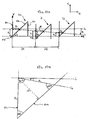
- three test patterns 70, 71 and 72 are printed. These are shown in Figure 10a .
- the first and third test patterns 70 and 72 are printed by a single reference printhead; in this example this is the black printhead 38.
- the second test pattern 71 is printed by a different printhead, the offset in the media feed direction of which is to be measured relative to the reference printhead; in this example the measured printhead is the cyan printhead 42.
- the second test pattern 71 is printed between the reference test patterns 70 and 72 in the direction of the scan axis.
- test patterns 70, 71 and 72 are identical, differing only in their placement on the print medium 33. Further, they each consists of three straight lines: lines 60a and 60c lying parallel to the media axis 13 and being positioned level with each other along the media axis; the line 60b joining one end of the line 60a and the opposing end of the line 60c so as to form a line at 45 degrees to both the media axis 13 and the scan axis 15.
- each test pattern 70, 71 and 72 is printed using all of the nozzles in the printhead and is printed at a predetermined location along the scan axis 15.
- the relative positions of the test patterns 70, 71 and 72 along the scan axis 15 are indicated by distances D1 and D2 in the figure.
- test patterns 70 and 72 being printed by the same printhead are printed level with each other in the media axis 13.
- the test pattern 71, which is printed by a different printhead is illustrated as having an offset in the media feed direction relative to the other test patterns 70, 72.
- the offset is illustrated in the figure by distance C 0 .
- the offset C 0 has been exaggerated in Figure 10a for the purposes of clarity.
- the optical detector 50a outputs detection pulses corresponding to detection of each of the lines 60a-c of each of the three test patterns 70-72, which are used to determine the positions of the test patterns in the media feed direction, as is described below.
- Figure 10a illustrates the "apparent" path of the optical sensor unit 50 when it scans the test patterns 70-72, superimposed over the test patterns 70-72.
- the "apparent" path of the optical sensor unit 50 is illustrated by the line L 2 .
- the line L 2 lies at an angle ⁇ to the direction of the scan axis relative to the print media when the test patterns 70-72 were printed, which is represented by the line L 1 .
- Figure 10a also illustrates the distance for each test pattern between its vertex 60d (referenced only in the case of the test pattern 70) and the point on its line 60a which is intersected by the line L 2 . These distances are K 1 , C and K 2 for test patterns 70, 71 and 72, respectively.
- the figure further illustrates the distances between the points on lines 60a and 60b intersected by the line L 2 , for each test pattern. These distances are A 1 , B and A 2 , for test patterns 70, 71 and 72, respectively.
- the X axis is parallel to the line L 1 and arranged such that the vertices 60d of both test patterns 70 and 72 lie on the X axis.
- the Y axis is positioned to be co-linear with the line 60a of the test pattern 70.
- Figure 10a also illustrates the distance C 1 between the X axis in the figure and the point on line 60a of test pattern 71 intersected by the line L 2 .
- the "actual" path of the optical sensor unit 50 may be parallel to the direction of the scan axis relative to the print media when the test patterns 70-72 were printed; i.e. the line L 1 .
- the varying pen to paper spacing may introduce errors into the measured distances lying between the different lines 60a-c of the different test patterns 70-72; thus, giving the impression of a deviation from the "actual" path of the optical sensor unit 50, which corresponds to the "apparent" path L 2 .
- Figure 10a represents only a small proportion of the distance along the scan axis 15 of the printer.
- the angular divergence of "apparent" path L 2 of the optical sensor unit, relative to the line L 1 will vary in dependence on the position along the scan axis.
- the line L 2 may trace a sinusoidal path varying about the line L 1 in the positive and negative media feed axis 13 relative to the line L 1 .
- the line L 2 may represent the actual path of the optical sensor unit 50 as it scans the test patterns 70-72.
- the angle ⁇ represents the angle by which the print media is skewed, for example, through a sheet feed operation.
- the processor of the printer determines the distances A 1 , B and A 2 , separating the points at which the "apparent" path L 2 crosses the lines 60a and 60b in test patterns 70, 71 and 72, respectively. This may be achieved in the same manner that the separation "d 1 " was determined in the first embodiment.
- the processor of the printer determines the offset C 0 between the cyan test pattern 71 and the black test patterns 70 and 72 in the media feed direction in the following manner.
- FIG. 10b an enlarged trigonometric representation of part of the test pattern 70 is shown.
- the figure illustrates the lines L 1 and L 2 , the angle ⁇ .
- the distances and the directions of K 1 and A 1 are shown.
- K 1 A 1 * sin 45 + ⁇ sin 45
- the offset correction C 0 is determined by interpolating between the measured distances for the two reference test patterns 70 and 72.
- the offset distance C 0 is then calculated by the processor of the printer.
- the processor of the printer implements the correction to the positioning of the cyan printhead 42 in the media feed direction. This may then be carried out in the same manner as described in the first embodiment.
- the offset distance relative to the black reference printhead is then determined in the same manner for each of the remaining printheads; thus ensuring that each printhead is satisfactorily aligned in the media feed direction with the reference printhead.
- a printhead under test prints a row consisting of numerous test patterns across the scan axis, which are alternated with test patterns printed by the reference printhead.
- test patterns printed by the reference printhead may be used, for interpolation purposes, to establish the relative offset of test patterns printed on either side of it along the scan axis, by the printhead under test printed.
- the present embodiment need not be limited to calculating the relative offset of a given test pattern by using a straight line interpolating technique between two reference test patterns.
- a conventional curve fitting technique could be used to fit a polynomial curve to the measurements of a number of reference test patterns; i.e. greater than two.
- the measured offset of each test pattern printed by the printhead under test could be established relative to co-ordinates of the fitted curve at the position along the scan axis corresponding to the position of that test pattern.
- the offset distance relative to the black reference printhead may then be determined in the same manner for each of the remaining printheads; thus ensuring that each printhead is satisfactorily aligned in the media feed direction with the reference printhead.
- the present invention may be applied to devices other that ink jet printer such as, for example traditional plotters which utilise felt-tipped pens and the like.
- ink jet printer such as, for example traditional plotters which utilise felt-tipped pens and the like.
- present invention is also applicable to monochrome printers.
- printers that employ two, three or more than four printheads.
- the invention may also be used to advantage with printers having only one printhead, should the exact placement in the direction of the media axis of the printed output need to be measured or controlled.
- the printhead test patterns may be varied in a variety of ways.
- the present invention may be implemented using a reduced number of lines parallel to the media axis (X-axis).
- the invention may be implemented using printhead alignment patterns which have only one of lines 60a and 60c; in the case shown in the figure, only line 60a.
- both of the lines 60a and 60c may be dispensed with in the printhead alignment pattern. This is shown in Figure 11b .
- the position measurement normally made by measuring the position of the line 60a along the scan axis may be replaced by the recorded position along the scan axis of a nozzle that printed a particular known point in the alignment pattern at the time that it was printed; for example one or other of the ends a or b of the line 60b, as shown in Figure 11 b.
- each alignment pattern was printed using all of the nozzles in the printhead, the skilled person will appreciate that this need not be the case.
- each alignment pattern may instead by printed using just selected nozzles of the printhead.
- half of the nozzles in one column could be used, as is shown in Figure 11c .
- the nozzles located about the center of one column are used in order to allow the patterns to be centrally located with respect to the path of the optical sensor unit 50.
- the alignment patterns may each be arranged to overlap the path of the optical scanner unit.
- the optical scanner may determine the position of each of the alignment patterns in one pass of the print media, without it being necessary to feed the print media in order to individually position each alignment pattern in order that it might be detected by the optical scanner.
- the angle of 45 degrees of the line 60b joining the two lines 60a and 60c parallel to the media movement direction (X-axis) may be varied to a different known angle.
- the printhead offset in the media direction may in this case be determined by finding the measurement made in the scan axis direction in a look up table relating measurements made in the scan axis direction with printhead offset in the media direction.
- a simple trigonometric calculation may be preformed in order to determine the offset in the media movement direction (X-axis) direction from the measurement made in carriage movement direction (Y-axis).
- a further example of a different alignment pattern which may be used in conjunction with the present invention may include a curved line or curved edge of a graphic instead of a straight line, such as 60b of the above embodiments, for determining the printhead offset in the media axis.
- the offset of the pattern in the media direction may be determined from the measurement of the position of the pattern in scan axis.
- the printhead offset in the media direction may be determined by finding the measurement made in the scan axis direction in a look up table relating measurements made in the scan axis direction with printhead offset in the media direction.
- the present invention may be implemented using a detector other than an optical detector in order to determine the position of aspects of the alignment patterns.
- Any suitable property of the mark which differentiates it from the medium upon which it is located may be used in order to determine its position.
- the invention may be implemented using a sensor that detects the magnetic or conductive properties, instead of the optical properties of the marks.
- the scanning step to detect the position of the alignment patterns need not be performed on the same pass of the carriage over the print media as that in which the alignment patterns are printed. In practice this could be implemented on any subsequent pass of the printer carriage over the print medium. However, if the scanning step is implemented on the return pass of the printer carriage or in any subsequent pass in the reverse direction, the order in which the pulses output by the optical detector as it passes over each line of each alignment pattern will be reversed.
- the process of reducing the offset in the media feed direction between printheads relies upon excluding certain nozzles from use and resetting the "logical zero" in terms of the nozzles' numbering
- the skilled person will realise that the other methods may be used to implement the present invention.
- an electro-mechanical system to physically move the printheads into alignment along the media movement axis. This may be achieved for each printhead, for example, by using a piezo-electric actuator to move the printhead and a position sensor to detect the resultant change in position of the printhead.
Claims (18)
- Procédé destiné à déterminer un décalage de positionnement ou un défaut d'alignement dans un appareil de tirage dans lequel un stylo et un capteur sont supportés chacun par un chariot d'impression disposé de façon à traverser un support dans des directions vers l'avant et vers l'arrière le long d'un axe de balayage, l'axe de balayage étant sensiblement parallèle à une première direction, le procédé comprenant les étapes consistant à :➢ marquer un motif d'alignement (70) sur un support d'impression avec un premier stylo (38), le motif comprenant une pluralité de points disposés de manière à former une ligne oblique (60b) par rapport à la première direction, cette ligne étant la seule ligne oblique du motif ;➢ traverser le motif dans une première direction (Y) avec un capteur et déterminer la position où la ligne oblique coupe le chemin (65) traversé par le capteur ; et➢ déterminer le décalage du centre du motif d'alignement à partir du centre du chemin traversé par le capteur dans une deuxième direction (X), le long d'un axe d'alimentation du support d'impression, le motif étant configuré de telle sorte que la position mesurée dans la première direction (Y) soit indicative d'un décalage de positionnement (Ob) dans une deuxième direction (X).
- Procédé selon la revendication 1, dans lequel l'étape consistant à déterminer le décalage du motif comprend en outre l'étape consistant à se référer à une table de consultation qui associe des valeurs de la position déterminée à des distances de décalage ou à exécuter une fonction mathématique sur la valeur de position déterminée de façon à déterminer le décalage du motif.
- Procédé selon la revendication 1, dans lequel les étapes de marquage et de détermination sont mises en application au cours d'un seul déplacement du chariot dans une seule direction le long de l'axe de balayage.
- Procédé selon la revendication 1, dans lequel le support d'impression est maintenu fixe par rapport à l'appareil entre les étapes de marquage et de détermination de la position d'une partie du motif dans la première direction.
- Procédé selon la revendication 1, dans lequel le motif comprend en outre une autre pluralité de points disposés de manière à former une deuxième ligne, la deuxième ligne étant orientée selon un angle sensiblement perpendiculaire à la première direction et sensiblement séparée de la ligne oblique dans la première direction.
- Procédé selon la revendication 5, dans lequel l'étape consistant à déterminer la position où la ligne oblique coupe le chemin (65) traversé par le capteur comprend l'étape consistant à mesurer la distance le long d'un chemin suivi par le capteur entre les points où la ligne oblique et la deuxième ligne sont sous-tendues par le chemin du capteur.
- Procédé selon l'une quelconque des revendications précédentes, dans lequel l'appareil comprend en outre un autre stylo, dans lequel le procédé comprend en outre, en ce qui concerne l'autre stylo, les étapes consistant à :➢ marquer un premier autre motif d'alignement (70) sur un support d'impression, le motif comprenant une pluralité de points disposés de manière à former une ligne oblique (62b) par rapport à la première direction, cette ligne étant la seule ligne oblique du premier autre motif ;➢ traverser le premier autre motif dans une première direction avec le capteur et déterminer la position où la ligne oblique coupe le chemin (65) traversé par le capteur et déterminer la position où la ligne oblique coupe le chemin (65) traversé par le capteur ; et,➢ déterminer le décalage (Oc) du centre du premier autre motif à partir du centre du chemin traversé par le capteur dans la deuxième direction, le premier autre motif étant configuré de telle sorte que la position mesurée dans la première direction soit indicative de son décalage de positionnement dans la deuxième direction.
- Procédé selon la revendication 7, comprenant en outre l'étape consistant à comparer le décalage du premier motif (70) et le décalage du premier autre motif (71).
- Procédé selon la revendication 7 ou la revendication 8, comprenant en outre les étapes consistant à :➢marquer avec l'autre stylo un deuxième autre motif d'alignement (72) sur le support d'impression espacé du premier autre motif (71) le long de l'axe de balayage, le deuxième autre motif comprenant une pluralité de points disposés de manière à former une ligne oblique (64b) par rapport à la première direction (Y), cette ligne étant la seule ligne oblique du deuxième autre motif ;➢ répéter les étapes de mesure et de détermination de la revendication 7 en ce qui concerne le deuxième autre motif (72), le deuxième autre motif (72) étant configuré de manière à présenter une position mesurée dans la première direction (Y) qui est indicative d'un décalage de positionnement dans la deuxième direction (X) ; et,➢ comparer les décalages déterminés en ce qui concerne les premier (71) et deuxième (72) autres motifs, de façon à détecter une erreur introduite dans le décalage de positionnement.
- Procédé selon la revendication 9, comprenant en outre l'étape consistant à déterminer l'erreur dans la mesure du décalage de positionnement du motif d'alignement imprimé par le premier stylo par interpolation ou extrapolation à partir des décalages mesurés des premier et deuxième autres motifs d'alignement jusqu'à la position le long de l'axe de balayage qui correspond à la position du motif d'alignement imprimé par le premier stylo.
- Procédé selon la revendication 10, comprenant en outre les étapes consistant à :➢ imprimer un ou plusieurs autres motifs d'alignement avec le premier stylo qui s'étend sensiblement à travers l'axe de balayage ;➢ répéter les étapes consistant à déterminer le décalage dans la deuxième direction et à déterminer l'erreur dans la mesure du décalage pour chacun desdits un ou plusieurs motifs d'alignement ; et,➢ déterminer une correction de décalage sur la base de l'ensemble des erreurs de décalage desdits un ou plusieurs motifs d'alignement.
- Procédé selon la revendication 11, comprenant en outre les étapes consistant à :➢ imprimer un ou plusieurs autres motifs d'alignement imprimés par l'autre stylo intercalés avec la pluralité de motifs d'alignement imprimés par le premier stylo ; et➢ utiliser le ou les autres motifs d'alignement de manière à établir l'erreur dans la mesure de décalage du ou des autres motifs d'alignement imprimés par le premier stylo.
- Procédé selon la revendication 12, comprenant en outre les étapes consistant à ajuster une courbe polynômiale à trois des décalages déterminés, ou plus, qui correspondent au premier, au deuxième ou aux autres motifs d'alignement de façon à accroître la précision de la détermination de l'erreur dans le décalage du motif d'alignement imprimé par le premier stylo par interpolation ou extrapolation.
- Procédé selon l'une quelconque des revendications 8 à 13, comprenant en outre l'étape consistant à ajuster la position de sortie d'impression du premier ou de l'autre stylo selon le décalage relatif du premier stylo et de l'autre stylo comprenant toute erreur détectée par le procédé de mesure de décalage.
- Procédé selon l'une quelconque des revendications précédentes, dans lequel ledit appareil de tirage est un appareil à jet d'encre, et dans lequel le premier stylo et / ou l'autre stylo comprennent une pluralité de buses d'éjection d'encre.
- Procédé selon la revendication 14 ou la revendication 15, dans lequel l'étape consistant à ajuster la position de sortie d'impression du ou des stylos comprend l'étape consistant à ajuster la position de l'un des stylos dans le chariot d'imprimante ou l'étape consistant à exclure d'une utilisation des buses sélectionnées de la tête d'impression.
- Dispositif de tirage comprenant un stylo agencé de manière à marquer un support d'impression, le dispositif comprenant en outre un capteur optique configuré de façon à se déplacer par rapport au support d'impression le long d'un chemin de capteur et à détecter des marques sur celui-ci, le stylo étant configuré de manière à imprimer un motif d'alignement sur les supports d'impression qui coupe le chemin du capteur, le motif comprenant une pluralité de points disposés de façon à former une ligne oblique (60b) par rapport au chemin du capteur, cette ligne étant la seule ligne oblique du motif, le motif étant configuré de manière à couper l'axe du capteur en un point qui correspond au décalage de la tête d'impression dans la direction sensiblement perpendiculaire à l'axe du capteur, le capteur étant configuré de façon à déterminer la position du motif d'alignement le long de l'axe de balayage.
- Programme informatique comprenant des moyens de code de programme destinés à exécuter les étapes du procédé selon l'une quelconque des revendications 1 à 16 lorsque le programme est exécuté sur un ordinateur et/ou d'autres moyens de traitement associés à un appareil de tirage approprié.
Priority Applications (4)
| Application Number | Priority Date | Filing Date | Title |
|---|---|---|---|
| EP01121159A EP1245399B1 (fr) | 2001-03-30 | 2001-09-04 | Méthode d'alignement améliorée pour dispositif d'impression et appareil correspondant |
| JP2002085749A JP2002361965A (ja) | 2001-03-30 | 2002-03-26 | プリンタ装置の位置合わせ方法及び装置 |
| US10/113,856 US6755499B2 (en) | 2001-03-30 | 2002-03-28 | Printer device alignment method and apparatus |
| US10/831,607 US20040196325A1 (en) | 2001-03-30 | 2004-04-23 | Printer device alignment method and apparatus |
Applications Claiming Priority (3)
| Application Number | Priority Date | Filing Date | Title |
|---|---|---|---|
| EP01108128 | 2001-03-30 | ||
| EP01108128A EP1245398A1 (fr) | 2001-03-30 | 2001-03-30 | Méthode d'alignement pour appareil d'impression et dispositif associé |
| EP01121159A EP1245399B1 (fr) | 2001-03-30 | 2001-09-04 | Méthode d'alignement améliorée pour dispositif d'impression et appareil correspondant |
Publications (3)
| Publication Number | Publication Date |
|---|---|
| EP1245399A2 EP1245399A2 (fr) | 2002-10-02 |
| EP1245399A3 EP1245399A3 (fr) | 2007-08-08 |
| EP1245399B1 true EP1245399B1 (fr) | 2010-03-03 |
Family
ID=26076523
Family Applications (1)
| Application Number | Title | Priority Date | Filing Date |
|---|---|---|---|
| EP01121159A Expired - Lifetime EP1245399B1 (fr) | 2001-03-30 | 2001-09-04 | Méthode d'alignement améliorée pour dispositif d'impression et appareil correspondant |
Country Status (3)
| Country | Link |
|---|---|
| US (2) | US6755499B2 (fr) |
| EP (1) | EP1245399B1 (fr) |
| JP (1) | JP2002361965A (fr) |
Families Citing this family (43)
| Publication number | Priority date | Publication date | Assignee | Title |
|---|---|---|---|---|
| US6007318A (en) | 1996-12-20 | 1999-12-28 | Z Corporation | Method and apparatus for prototyping a three-dimensional object |
| US7037382B2 (en) * | 1996-12-20 | 2006-05-02 | Z Corporation | Three-dimensional printer |
| EP1245399B1 (fr) * | 2001-03-30 | 2010-03-03 | Hewlett-Packard Company, A Delaware Corporation | Méthode d'alignement améliorée pour dispositif d'impression et appareil correspondant |
| US6827419B2 (en) * | 2002-09-26 | 2004-12-07 | Hewlett-Packard Development Company, L.P. | Media allignment method and system |
| KR100490427B1 (ko) * | 2003-02-14 | 2005-05-17 | 삼성전자주식회사 | 잉크젯 프린터의 인쇄 정렬오차 보정방법 |
| KR100449749B1 (ko) * | 2003-02-15 | 2004-09-22 | 삼성전자주식회사 | 잉크젯 프린터의 용지 피딩량 보정방법 |
| US7291002B2 (en) * | 2003-05-23 | 2007-11-06 | Z Corporation | Apparatus and methods for 3D printing |
| US20050013647A1 (en) * | 2003-06-28 | 2005-01-20 | David Claramunt | Media marking for optical sensing of media advancement |
| US7267419B2 (en) * | 2003-09-03 | 2007-09-11 | Seiko Epson Corporation | Method for liquid ejection and liquid ejecting apparatus |
| US7036904B2 (en) * | 2003-10-30 | 2006-05-02 | Lexmark International, Inc. | Printhead swath height measurement and compensation for ink jet printing |
| US20050253888A1 (en) * | 2004-05-12 | 2005-11-17 | Robert Fogarty | Evaluating an image forming device |
| US7824001B2 (en) * | 2004-09-21 | 2010-11-02 | Z Corporation | Apparatus and methods for servicing 3D printers |
| US7387359B2 (en) * | 2004-09-21 | 2008-06-17 | Z Corporation | Apparatus and methods for servicing 3D printers |
| US7431417B2 (en) * | 2004-10-27 | 2008-10-07 | Hewlett-Packard Development Company, L.P. | Ink density impact on sensor signal-to-noise ratio |
| GB2428638B (en) * | 2005-07-29 | 2009-09-09 | Hewlett Packard Development Co | Method of estimating alignment |
| US7731330B2 (en) * | 2005-09-26 | 2010-06-08 | Seiko Epson Corporation | Position detecting device, liquid ejecting apparatus and method of detecting smear of scale |
| US7547086B2 (en) * | 2005-12-01 | 2009-06-16 | Fujifilm Corporation | Recording medium conveyance amount measurement method and inkjet recording apparatus |
| WO2007139938A2 (fr) | 2006-05-26 | 2007-12-06 | Z Corporation | Appareil et procédés pour le maniement de matériaux dans une imprimante 3d |
| US7588302B2 (en) * | 2006-07-31 | 2009-09-15 | Hewlett-Packard Development Company, L.P. | System and method for detecting pen-to-paper spacing in a printing system |
| US9254698B2 (en) * | 2007-01-26 | 2016-02-09 | Hewlett-Packard Development Company, L.P. | Printing apparatus |
| AU2007203294A1 (en) * | 2007-07-17 | 2009-02-05 | Canon Kabushiki Kaisha | Method of measuring printer characteristics |
| US20090026265A1 (en) * | 2007-07-25 | 2009-01-29 | Grosse Jason C | Determining a position of a print carriage |
| EP2209648A4 (fr) * | 2007-10-09 | 2011-12-28 | Scodix Ltd | Système et procédé de surimpression |
| EP2103432B1 (fr) * | 2008-03-10 | 2014-08-20 | Océ-Technologies B.V. | Procédé et appareil pour détecter une touche support de tête d'impression |
| EP2365910B1 (fr) * | 2008-11-17 | 2016-06-29 | OCE-Technologies B.V. | Procédé d'alignement de plusieurs éléments et dispositif comportant plusieurs éléments |
| US8462407B2 (en) * | 2008-12-17 | 2013-06-11 | Canon Kabushiki Kaisha | Measuring separation of patterns, and use thereof for determining printer characteristics |
| AU2008258213B2 (en) * | 2008-12-18 | 2012-01-12 | Canon Kabushiki Kaisha | Method of measuring printer spatial characteristics |
| US8136913B2 (en) * | 2009-03-20 | 2012-03-20 | Xerox Corporation | System and method for measuring drop position in an image of a test pattern on an image substrate |
| US8118391B2 (en) * | 2009-04-29 | 2012-02-21 | Xerox Corporation | Method for calibration |
| US8520266B2 (en) * | 2009-11-24 | 2013-08-27 | Xerox Corporation | Method and apparatus for measuring image on paper registration |
| US9016820B2 (en) | 2011-08-24 | 2015-04-28 | Canon Kabushiki Kaisha | Printing apparatus and control method thereof |
| CN104080615B (zh) | 2012-02-07 | 2016-03-16 | 惠普发展公司,有限责任合伙企业 | 颜色分析 |
| JP6046171B2 (ja) * | 2012-03-09 | 2016-12-14 | オセ−テクノロジーズ ビーブイ | フルブリード印刷のための方法 |
| JP2014050975A (ja) | 2012-09-05 | 2014-03-20 | Casio Comput Co Ltd | 印刷装置及び被印刷媒体 |
| US9132626B2 (en) * | 2014-01-24 | 2015-09-15 | Xerox Corporation | System and method for measuring cross-talk in inkjet printheads |
| US9352572B2 (en) * | 2014-03-31 | 2016-05-31 | Xerox Corporation | System for detecting inoperative inkjets in three-dimensional object printing using an optical sensor and movable test substrates |
| US9346301B2 (en) * | 2014-07-31 | 2016-05-24 | Eastman Kodak Company | Controlling a web-fed printer using an image region database |
| WO2016029925A1 (fr) * | 2014-08-25 | 2016-03-03 | Hewlett-Packard Development Company, L.P. | Détermination d'une caractéristique d'alignement |
| JP5824712B1 (ja) | 2014-10-28 | 2015-11-25 | 株式会社デュプロ | インクジェット記録装置 |
| US10744714B2 (en) | 2015-04-30 | 2020-08-18 | Hewlett-Packard Development Company, L.P. | Misalignment detection for a 3D printing device |
| US9956799B1 (en) | 2017-01-24 | 2018-05-01 | Ricoh Company, Ltd. | Test patterns for optimizing nozzle alignment of an ink-jet marking engine |
| US10101701B1 (en) * | 2017-09-05 | 2018-10-16 | Xerox Corporation | Paper path sensing of non-reflective paper with reflective sensors |
| CN117470158B (zh) * | 2023-12-27 | 2024-04-23 | 湖南肆玖科技有限公司 | 一种用于刻字机的巡边检测方法及系统 |
Family Cites Families (16)
| Publication number | Priority date | Publication date | Assignee | Title |
|---|---|---|---|---|
| JPS59224360A (ja) | 1983-05-07 | 1984-12-17 | Fuji Xerox Co Ltd | インクジエツトプリンタ用ドロツプセンサ |
| DE3885904D1 (de) | 1987-09-25 | 1994-01-05 | Siemens Ag | Anordnung zur überwachung des tröpfchenausstosses aus austrittsdüsen eines tintenschreibkopfes. |
| US4990932A (en) | 1989-09-26 | 1991-02-05 | Xerox Corporation | Ink droplet sensors for ink jet printers |
| US5975674A (en) | 1990-04-04 | 1999-11-02 | Hewlett-Packard Company | Optical path optimization for light transmission and reflection in a carriage-mounted inkjet printer sensor |
| US5404020A (en) * | 1993-04-30 | 1995-04-04 | Hewlett-Packard Company | Phase plate design for aligning multiple inkjet cartridges by scanning a reference pattern |
| ES2142025T3 (es) | 1995-05-22 | 2000-04-01 | Canon Kk | Sistema para la deteccion de fallos de inyeccion de tinta. |
| US5796414A (en) | 1996-03-25 | 1998-08-18 | Hewlett-Packard Company | Systems and method for establishing positional accuracy in two dimensions based on a sensor scan in one dimension |
| US5835108A (en) * | 1996-09-25 | 1998-11-10 | Hewlett-Packard Company | Calibration technique for mis-directed inkjet printhead nozzles |
| US6283572B1 (en) | 1997-03-04 | 2001-09-04 | Hewlett-Packard Company | Dynamic multi-pass print mode corrections to compensate for malfunctioning inkjet nozzles |
| JP3560305B2 (ja) * | 1997-03-28 | 2004-09-02 | キヤノン株式会社 | 記録装置およびチェックパターン記録方法 |
| US6310637B1 (en) | 1997-07-31 | 2001-10-30 | Seiko Epson Corporation | Method of printing test pattern and printing apparatus for the same |
| JP3410652B2 (ja) * | 1998-01-30 | 2003-05-26 | コピア株式会社 | インクジェット画像形成装置 |
| DE69931134T2 (de) | 1999-02-12 | 2007-04-19 | Hewlett-Packard Development Company, L.P., Houston | Verfahren zur Tintentropfenerfassung in einem Druckgerät |
| EP1033251B1 (fr) | 1999-02-19 | 2003-05-28 | Hewlett-Packard Company, A Delaware Corporation | Méthode d'impression pour compenser automatiquement des buses à jet d'encre défaillantes |
| US6623096B1 (en) * | 2000-07-28 | 2003-09-23 | Hewlett-Packard Company | Techniques for measuring the position of marks on media and for aligning inkjet devices |
| EP1245399B1 (fr) * | 2001-03-30 | 2010-03-03 | Hewlett-Packard Company, A Delaware Corporation | Méthode d'alignement améliorée pour dispositif d'impression et appareil correspondant |
-
2001
- 2001-09-04 EP EP01121159A patent/EP1245399B1/fr not_active Expired - Lifetime
-
2002
- 2002-03-26 JP JP2002085749A patent/JP2002361965A/ja active Pending
- 2002-03-28 US US10/113,856 patent/US6755499B2/en not_active Expired - Lifetime
-
2004
- 2004-04-23 US US10/831,607 patent/US20040196325A1/en not_active Abandoned
Also Published As
| Publication number | Publication date |
|---|---|
| US20020181986A1 (en) | 2002-12-05 |
| EP1245399A2 (fr) | 2002-10-02 |
| US20040196325A1 (en) | 2004-10-07 |
| JP2002361965A (ja) | 2002-12-18 |
| US6755499B2 (en) | 2004-06-29 |
| EP1245399A3 (fr) | 2007-08-08 |
Similar Documents
| Publication | Publication Date | Title |
|---|---|---|
| EP1245399B1 (fr) | Méthode d'alignement améliorée pour dispositif d'impression et appareil correspondant | |
| EP1176802B1 (fr) | Techniques pour mesurer la position des repères sur médias et pour aligner des dispositifs à jet d'encre | |
| US6331038B1 (en) | Techniques for robust dot placement error measurement and correction | |
| EP1034939B1 (fr) | Système d'alignement automatisé pour têtes d'impression à jet d'encre | |
| EP0775587B1 (fr) | Alignement d'une tête d'impression à jet d'encre par la mesure d'erreurs et une mémoire de données | |
| US6109722A (en) | Ink jet printing system with pen alignment and method | |
| JP4045092B2 (ja) | プリンタの改行較正方法 | |
| US20050073539A1 (en) | Ink placement adjustment | |
| US7044573B2 (en) | Printhead alignment test pattern and method for determining printhead misalignment | |
| KR20040073730A (ko) | 잉크젯 프린터의 인쇄 정렬오차 보정방법 | |
| KR20070120902A (ko) | 기록 장치 및 반송 방법 | |
| EP3317110B1 (fr) | Étalonnage de système d'avancée de support d'un dispositif d'impression de grand ensemble de pages | |
| US7571978B2 (en) | Correction value determining method, correction value determining apparatus, and storage medium having program stored thereon | |
| EP1516740B1 (fr) | Procédé et imprimante pour former une image sur un matériau récepteur | |
| US7891757B2 (en) | Marking element registration | |
| EP1413444B1 (fr) | Correction du désalignement du papier dans un dispositif d'impression | |
| US20050270325A1 (en) | System and method for calibrating ink ejecting nozzles in a printer/scanner | |
| US7413276B2 (en) | Diagnostic for visual detection of media advance errors | |
| US6411405B1 (en) | Method and apparatus for correcting scanning errors in a shuttle type scanner | |
| EP1245398A1 (fr) | Méthode d'alignement pour appareil d'impression et dispositif associé | |
| US7931347B2 (en) | Transporting method and recording apparatus | |
| US8376500B2 (en) | Image recording apparatus, method of calculating record position shifts, and method of recording measured patterns | |
| EP1775134B1 (fr) | Procédé pour déterminer l'alignement de têtes d'impression dans une imprimante |
Legal Events
| Date | Code | Title | Description |
|---|---|---|---|
| PUAI | Public reference made under article 153(3) epc to a published international application that has entered the european phase |
Free format text: ORIGINAL CODE: 0009012 |
|
| AK | Designated contracting states |
Kind code of ref document: A2 Designated state(s): AT BE CH CY DE DK ES FI FR GB GR IE IT LI LU MC NL PT SE TR |
|
| AX | Request for extension of the european patent |
Free format text: AL;LT;LV;MK;RO;SI |
|
| PUAL | Search report despatched |
Free format text: ORIGINAL CODE: 0009013 |
|
| AK | Designated contracting states |
Kind code of ref document: A3 Designated state(s): AT BE CH CY DE DK ES FI FR GB GR IE IT LI LU MC NL PT SE TR |
|
| AX | Request for extension of the european patent |
Extension state: AL LT LV MK RO SI |
|
| AKX | Designation fees paid |
Designated state(s): AT BE CH CY DE DK ES FI FR GB GR IE IT LI LU MC NL PT SE TR |
|
| 17P | Request for examination filed |
Effective date: 20060205 |
|
| 17Q | First examination report despatched |
Effective date: 20081230 |
|
| GRAP | Despatch of communication of intention to grant a patent |
Free format text: ORIGINAL CODE: EPIDOSNIGR1 |
|
| GRAS | Grant fee paid |
Free format text: ORIGINAL CODE: EPIDOSNIGR3 |
|
| GRAA | (expected) grant |
Free format text: ORIGINAL CODE: 0009210 |
|
| AK | Designated contracting states |
Kind code of ref document: B1 Designated state(s): AT BE CH CY DE DK ES FI FR GB GR IE IT LI LU MC NL PT SE TR |
|
| REG | Reference to a national code |
Ref country code: GB Ref legal event code: FG4D |
|
| REG | Reference to a national code |
Ref country code: CH Ref legal event code: EP |
|
| REG | Reference to a national code |
Ref country code: IE Ref legal event code: FG4D |
|
| REF | Corresponds to: |
Ref document number: 60141451 Country of ref document: DE Date of ref document: 20100415 Kind code of ref document: P |
|
| REG | Reference to a national code |
Ref country code: NL Ref legal event code: VDEP Effective date: 20100303 |
|
| PG25 | Lapsed in a contracting state [announced via postgrant information from national office to epo] |
Ref country code: AT Free format text: LAPSE BECAUSE OF FAILURE TO SUBMIT A TRANSLATION OF THE DESCRIPTION OR TO PAY THE FEE WITHIN THE PRESCRIBED TIME-LIMIT Effective date: 20100303 Ref country code: FI Free format text: LAPSE BECAUSE OF FAILURE TO SUBMIT A TRANSLATION OF THE DESCRIPTION OR TO PAY THE FEE WITHIN THE PRESCRIBED TIME-LIMIT Effective date: 20100303 |
|
| PG25 | Lapsed in a contracting state [announced via postgrant information from national office to epo] |
Ref country code: SE Free format text: LAPSE BECAUSE OF FAILURE TO SUBMIT A TRANSLATION OF THE DESCRIPTION OR TO PAY THE FEE WITHIN THE PRESCRIBED TIME-LIMIT Effective date: 20100303 Ref country code: CY Free format text: LAPSE BECAUSE OF FAILURE TO SUBMIT A TRANSLATION OF THE DESCRIPTION OR TO PAY THE FEE WITHIN THE PRESCRIBED TIME-LIMIT Effective date: 20100303 Ref country code: ES Free format text: LAPSE BECAUSE OF FAILURE TO SUBMIT A TRANSLATION OF THE DESCRIPTION OR TO PAY THE FEE WITHIN THE PRESCRIBED TIME-LIMIT Effective date: 20100614 Ref country code: GR Free format text: LAPSE BECAUSE OF FAILURE TO SUBMIT A TRANSLATION OF THE DESCRIPTION OR TO PAY THE FEE WITHIN THE PRESCRIBED TIME-LIMIT Effective date: 20100604 Ref country code: NL Free format text: LAPSE BECAUSE OF FAILURE TO SUBMIT A TRANSLATION OF THE DESCRIPTION OR TO PAY THE FEE WITHIN THE PRESCRIBED TIME-LIMIT Effective date: 20100303 Ref country code: BE Free format text: LAPSE BECAUSE OF FAILURE TO SUBMIT A TRANSLATION OF THE DESCRIPTION OR TO PAY THE FEE WITHIN THE PRESCRIBED TIME-LIMIT Effective date: 20100303 |
|
| PLBE | No opposition filed within time limit |
Free format text: ORIGINAL CODE: 0009261 |
|
| STAA | Information on the status of an ep patent application or granted ep patent |
Free format text: STATUS: NO OPPOSITION FILED WITHIN TIME LIMIT |
|
| PG25 | Lapsed in a contracting state [announced via postgrant information from national office to epo] |
Ref country code: PT Free format text: LAPSE BECAUSE OF FAILURE TO SUBMIT A TRANSLATION OF THE DESCRIPTION OR TO PAY THE FEE WITHIN THE PRESCRIBED TIME-LIMIT Effective date: 20100705 Ref country code: DK Free format text: LAPSE BECAUSE OF FAILURE TO SUBMIT A TRANSLATION OF THE DESCRIPTION OR TO PAY THE FEE WITHIN THE PRESCRIBED TIME-LIMIT Effective date: 20100303 |
|
| 26N | No opposition filed |
Effective date: 20101206 |
|
| PG25 | Lapsed in a contracting state [announced via postgrant information from national office to epo] |
Ref country code: IT Free format text: LAPSE BECAUSE OF FAILURE TO SUBMIT A TRANSLATION OF THE DESCRIPTION OR TO PAY THE FEE WITHIN THE PRESCRIBED TIME-LIMIT Effective date: 20100303 |
|
| PG25 | Lapsed in a contracting state [announced via postgrant information from national office to epo] |
Ref country code: MC Free format text: LAPSE BECAUSE OF NON-PAYMENT OF DUE FEES Effective date: 20100930 |
|
| REG | Reference to a national code |
Ref country code: CH Ref legal event code: PL |
|
| PG25 | Lapsed in a contracting state [announced via postgrant information from national office to epo] |
Ref country code: CH Free format text: LAPSE BECAUSE OF NON-PAYMENT OF DUE FEES Effective date: 20100930 Ref country code: LI Free format text: LAPSE BECAUSE OF NON-PAYMENT OF DUE FEES Effective date: 20100930 Ref country code: IE Free format text: LAPSE BECAUSE OF NON-PAYMENT OF DUE FEES Effective date: 20100904 |
|
| REG | Reference to a national code |
Ref country code: GB Ref legal event code: 732E Free format text: REGISTERED BETWEEN 20120329 AND 20120404 |
|
| PG25 | Lapsed in a contracting state [announced via postgrant information from national office to epo] |
Ref country code: LU Free format text: LAPSE BECAUSE OF NON-PAYMENT OF DUE FEES Effective date: 20100904 |
|
| PG25 | Lapsed in a contracting state [announced via postgrant information from national office to epo] |
Ref country code: TR Free format text: LAPSE BECAUSE OF FAILURE TO SUBMIT A TRANSLATION OF THE DESCRIPTION OR TO PAY THE FEE WITHIN THE PRESCRIBED TIME-LIMIT Effective date: 20100303 |
|
| REG | Reference to a national code |
Ref country code: FR Ref legal event code: PLFP Year of fee payment: 16 |
|
| REG | Reference to a national code |
Ref country code: FR Ref legal event code: PLFP Year of fee payment: 17 |
|
| PGFP | Annual fee paid to national office [announced via postgrant information from national office to epo] |
Ref country code: GB Payment date: 20170821 Year of fee payment: 17 Ref country code: DE Payment date: 20170821 Year of fee payment: 17 Ref country code: FR Payment date: 20170822 Year of fee payment: 17 |
|
| REG | Reference to a national code |
Ref country code: DE Ref legal event code: R119 Ref document number: 60141451 Country of ref document: DE |
|
| GBPC | Gb: european patent ceased through non-payment of renewal fee |
Effective date: 20180904 |
|
| PG25 | Lapsed in a contracting state [announced via postgrant information from national office to epo] |
Ref country code: DE Free format text: LAPSE BECAUSE OF NON-PAYMENT OF DUE FEES Effective date: 20190402 |
|
| PG25 | Lapsed in a contracting state [announced via postgrant information from national office to epo] |
Ref country code: FR Free format text: LAPSE BECAUSE OF NON-PAYMENT OF DUE FEES Effective date: 20180930 |
|
| PG25 | Lapsed in a contracting state [announced via postgrant information from national office to epo] |
Ref country code: GB Free format text: LAPSE BECAUSE OF NON-PAYMENT OF DUE FEES Effective date: 20180904 |