EP1245101B1 - Method and apparatus for buffering data samples in a software based adsl modem - Google Patents
Method and apparatus for buffering data samples in a software based adsl modem Download PDFInfo
- Publication number
- EP1245101B1 EP1245101B1 EP00951017A EP00951017A EP1245101B1 EP 1245101 B1 EP1245101 B1 EP 1245101B1 EP 00951017 A EP00951017 A EP 00951017A EP 00951017 A EP00951017 A EP 00951017A EP 1245101 B1 EP1245101 B1 EP 1245101B1
- Authority
- EP
- European Patent Office
- Prior art keywords
- symbol
- data
- buffer
- synch
- symbols
- Prior art date
- Legal status (The legal status is an assumption and is not a legal conclusion. Google has not performed a legal analysis and makes no representation as to the accuracy of the status listed.)
- Expired - Lifetime
Links
- 238000000034 method Methods 0.000 title claims description 18
- 230000003139 buffering effect Effects 0.000 title description 2
- 230000006854 communication Effects 0.000 claims description 77
- 238000004891 communication Methods 0.000 claims description 77
- 239000000872 buffer Substances 0.000 claims description 65
- 230000005540 biological transmission Effects 0.000 claims description 11
- 230000004044 response Effects 0.000 claims description 7
- 238000012545 processing Methods 0.000 claims description 6
- 230000003111 delayed effect Effects 0.000 claims description 4
- 238000003780 insertion Methods 0.000 claims description 4
- 230000037431 insertion Effects 0.000 claims description 4
- 239000012723 sample buffer Substances 0.000 description 21
- 238000012546 transfer Methods 0.000 description 15
- 230000006870 function Effects 0.000 description 14
- 125000004122 cyclic group Chemical group 0.000 description 10
- 238000010586 diagram Methods 0.000 description 10
- 238000005516 engineering process Methods 0.000 description 6
- 239000000523 sample Substances 0.000 description 4
- 238000012549 training Methods 0.000 description 4
- 238000011144 upstream manufacturing Methods 0.000 description 4
- 230000008901 benefit Effects 0.000 description 3
- 238000012986 modification Methods 0.000 description 3
- 230000004048 modification Effects 0.000 description 3
- 238000012937 correction Methods 0.000 description 2
- 230000006735 deficit Effects 0.000 description 2
- 238000011161 development Methods 0.000 description 2
- 238000012423 maintenance Methods 0.000 description 2
- 230000008569 process Effects 0.000 description 2
- 241000784732 Lycaena phlaeas Species 0.000 description 1
- 230000007175 bidirectional communication Effects 0.000 description 1
- 239000000969 carrier Substances 0.000 description 1
- 238000006243 chemical reaction Methods 0.000 description 1
- 230000006835 compression Effects 0.000 description 1
- 238000007906 compression Methods 0.000 description 1
- 238000010276 construction Methods 0.000 description 1
- 230000008878 coupling Effects 0.000 description 1
- 238000010168 coupling process Methods 0.000 description 1
- 238000005859 coupling reaction Methods 0.000 description 1
- 230000003247 decreasing effect Effects 0.000 description 1
- 230000001934 delay Effects 0.000 description 1
- 238000013461 design Methods 0.000 description 1
- 238000001514 detection method Methods 0.000 description 1
- 230000000694 effects Effects 0.000 description 1
- 239000000835 fiber Substances 0.000 description 1
- 238000009434 installation Methods 0.000 description 1
- 230000003993 interaction Effects 0.000 description 1
- 238000004519 manufacturing process Methods 0.000 description 1
- 230000002093 peripheral effect Effects 0.000 description 1
- 230000001105 regulatory effect Effects 0.000 description 1
- 230000011664 signaling Effects 0.000 description 1
Images


Classifications
-
- H—ELECTRICITY
- H04—ELECTRIC COMMUNICATION TECHNIQUE
- H04M—TELEPHONIC COMMUNICATION
- H04M11/00—Telephonic communication systems specially adapted for combination with other electrical systems
- H04M11/06—Simultaneous speech and data transmission, e.g. telegraphic transmission over the same conductors
- H04M11/062—Simultaneous speech and data transmission, e.g. telegraphic transmission over the same conductors using different frequency bands for speech and other data
-
- H—ELECTRICITY
- H04—ELECTRIC COMMUNICATION TECHNIQUE
- H04L—TRANSMISSION OF DIGITAL INFORMATION, e.g. TELEGRAPHIC COMMUNICATION
- H04L25/00—Baseband systems
- H04L25/02—Details ; arrangements for supplying electrical power along data transmission lines
- H04L25/05—Electric or magnetic storage of signals before transmitting or retransmitting for changing the transmission rate
-
- H—ELECTRICITY
- H04—ELECTRIC COMMUNICATION TECHNIQUE
- H04L—TRANSMISSION OF DIGITAL INFORMATION, e.g. TELEGRAPHIC COMMUNICATION
- H04L27/00—Modulated-carrier systems
- H04L27/26—Systems using multi-frequency codes
- H04L27/2601—Multicarrier modulation systems
-
- Y—GENERAL TAGGING OF NEW TECHNOLOGICAL DEVELOPMENTS; GENERAL TAGGING OF CROSS-SECTIONAL TECHNOLOGIES SPANNING OVER SEVERAL SECTIONS OF THE IPC; TECHNICAL SUBJECTS COVERED BY FORMER USPC CROSS-REFERENCE ART COLLECTIONS [XRACs] AND DIGESTS
- Y02—TECHNOLOGIES OR APPLICATIONS FOR MITIGATION OR ADAPTATION AGAINST CLIMATE CHANGE
- Y02D—CLIMATE CHANGE MITIGATION TECHNOLOGIES IN INFORMATION AND COMMUNICATION TECHNOLOGIES [ICT], I.E. INFORMATION AND COMMUNICATION TECHNOLOGIES AIMING AT THE REDUCTION OF THEIR OWN ENERGY USE
- Y02D30/00—Reducing energy consumption in communication networks
- Y02D30/50—Reducing energy consumption in communication networks in wire-line communication networks, e.g. low power modes or reduced link rate
Definitions
- the present invention relates generally to modem communications, and, more particularly, to a method and apparatus for buffering data samples in a software-based Asymmetric Digital Subscriber Line (ADSL) modern.
- ADSL Asymmetric Digital Subscriber Line
- DSL Digital Subscriber Line
- DSL technologies leave the POTS service undisturbed.
- Traditional analog voice band interfaces use the same frequency band, 0-4 Kilohertz (kHz), as telephone service, thereby preventing concurrent voice and data use.
- a DSL interface operates at frequencies above the voice channels from 100 kHz to 1.1 Megahertz (MHz). Thus, a single DSL line is capable of offering simultaneous channels for voice and data.
- DSL systems use digital signal processing (DSP) to increase throughput and signal quality through common copper telephone wire.
- DSL systems provide a downstream data transfer rate from the DSL Point-of-Presence (POP) to the subscriber location at speeds of about 1.5 Megabits per second (MBPS).
- POP Point-of-Presence
- MBPS Megabits per second
- ADSL Asymmetric Digital Subscriber Line
- the ADSL standard is described in ANSI T1.413 Issue 2, entitled, "Interface Between Networks and Customer Installation - Asymmetric Digital Subscriber Line (ADSL) Metallic Interface, Rev. R4, dated 6/12/98.
- ADSL modems use two competing modulation schemes: discrete multi-tone (DMT) and carrierless amplitude/phase modulation (CAP).
- DMT is the standard adopted by the American National Standards Institute. The standard defines 256 discrete tones, with each tone representing a carrier signal that can be modulated with a digital signal for transmitting data. The specific frequency for a given tone is 4.3125 kHz times the tone number. Tones 1-7 are reserved for voice band and guard band ( i.e., tone 1 is the voice band and tones 2-7 are guard bands). Data is not transmitted near the voice band to allow for simultaneous voice and data transmission on a single line. The guard band helps isolate the voice band from the ADSL data bands.
- a splitter may be used to isolate any voice band signal from the data tones.
- Tones 8-32 are used to transmit data upstream (i.e., from the user), and tones 33-256 are used to transmit data downstream ( i.e., to the user).
- all the data tones 8-256 may be used for downstream data, and upstream data present on tones 8-32 would be detected using echo cancellation. Because more tones are used for downstream communication than for upstream communication, the transfer is said to be asymmetric.
- the modems on both sides of the connection sense and analyze which tones are less affected by impairments in the telephone line. Each tone that is accepted is used to carry information. Accordingly, the maximum capacity is set by the quality of the telephone connection.
- the maximum data rate defined by the ADSL specification assuming all tones are used, is about 8 MBPS downstream and about 640 KBPS upstream.
- a central office (CO) modem communicates with a customer premise (CP) modem.
- the CP modem is typically installed in a home or office.
- ADSL modems generally transmit and receive data in real-time.
- some real-time functions of these ADSL modems are being implemented as software routines, due to, among other things, decreased manufacturing costs and increased flexibility.
- These software routines are typically executed on a host computer running under a multi-tasking operating system, such as Microsoft Windows® , for example.
- the ADSL modem When performing non-real time functions, the ADSL modem is considered relatively unstable in that, at any particular time, the connection may be dropped or fail to transfer data properly if the operating system is delayed in providing the necessary support to the modem on a real-time basis. For example, if the operating system is delayed in providing modem routine processing or bus transfers on a real-time basis, the modem may drop its connection. This situation may occur when the operating system is heavily loaded servicing other routines, or when peripheral devices or device drivers seize system resources for relatively long periods of time. As a result of these dropped connections, the computer user is inconvenienced by having to re-establish the connection and re-initiate the data transfer.
- the present invention is directed to overcoming, or at least reducing the effects of, one or more of the problems set forth above.
- EP-A-0762655 discloses a host signal processing communication system that includes a circular transmit buffer.
- the host computer periodically adds samples to the circular buffer during interrupts, for example, and a D/A converter generates a transmitted analog communication signal from the samples in the circular buffer.
- the D/A converter generates a maintenance signal by repeatedly converting old samples from the circular buffer until the host computer provides new samples. Accordingly, the maintenance signal attempts to maintain the communication link and prevent a remote device from disconnecting.
- a method in one aspect of the present invention, includes generating data for transmission to a remote source and modulating the data to form a plurality of data symbols for transmission.
- the data symbols are stored in a buffer. It is determined if there is an absence of a data symbol in the buffer. In response to detecting an absence of a data symbol in the buffer, an idle data symbol is transmitted.
- an apparatus in another aspect of the present invention, includes a processor adapted to generate data for transmission to a remote source.
- the apparatus further includes a transmitter adapted to modulate the data to form a plurality of data symbols, store the data symbols in a buffer, determine an absence of a data symbol in the buffer, and transmit an idle data symbol in response to detecting an absence of a data symbol in the buffer.
- the communications system 100 includes a processor system 110 and a modem communication unit 120, coupled to the processor system 110 via a connection link 125.
- the modem communication unit 120 is a DMT ADSL modem.
- the communications system 100 communicates with a remote communications device 140, which is also a DMT ADSL modem in one embodiment, on a real-time and non-real-time basis over a communications link 130.
- the communications link 130 coupling the modem communication unit 120 and the remote communication unit 140 includes an ordinary twisted pair connection for communication via the Public Switched Telephone Network (PSTN) (not shown).
- PSTN Public Switched Telephone Network
- the communications system 100 resides in a customer premise (CP) 150, such as an office, home, or the like.
- the remote communication unit 140 is part of a central office 160.
- the remote communications unit 140 acts as a gateway to a larger communications network (not shown), such as a local or wide area network, or the Internet, for example.
- a larger communications network not shown
- the remote communications unit 140 may be installed in a second customer premise (not shown), instead of the central office 160, without departing from the spirit and scope of the present invention.
- the modern communication unit 120 establishes a connection to the communication network (not shown) through the remote communication unit 140.
- the modem communication unit 120 and the remote communication unit 140 engage in a training process whereby the throughput available for communication between the modem communication unit 120 and the remote communication unit 140 is determined. This may include, for example, ascertaining which tones are clear of impairments for modulating data thereon.
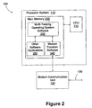
- the processor system 110 comprises a central processing unit (CPU) 210 and a main memory 220.
- the processor system 110 may be in the form of a personal computer available from a variety of manufacturers, such as Compaq Computer Corp., for example.
- the CPU 210 executes multi-tasking operating system software 230, modem function software 240, and other application software 250 that reside in the main memory 220.
- the multi-tasking operating system software 230 in-accordance with the illustrated embodiment, may not be real-time.
- the multi-tasking operating system software 230 may not always provide adequate resources from the CPU 210 to maintain continuous operation of the modem function software 240 and the other application software 250. This may result in a dropped communications link 130 between the modem communication unit 120 and the remote communication unit 140 or the loss of data therebetween.
- the modem communication unit 120 includes a transmitter 305 and a receiver 310.
- the transmitter 305 and receiver 310 interface with the communications link 130, such as a telephone line, for communicating with the remote communication unit 140.
- a control unit 315 interfaces with the transmitter 305 and the receiver 310 to control the operation thereof.
- the control unit 315 is programmed with instruction sets to enable the modem communication unit 120 to perform various functions, such as establishing a connection and training the connection, for example. The interaction of the control unit 315 with the transmitter 305 and the receiver 310 will be further described in detail as the description proceeds.
- the transmitter 305 includes an encoding unit 320 that receives outgoing digital data over a data-out line 325.
- the outgoing digital data is received from the processor system 110 that is coupled to the modem communications unit 120 over the connection link 125, in which the data-out line 325 forms a part of the link 125.
- the encoding unit 320 performs functions such as cyclic redundancy checking (CRC), scrambling, forward error correction, and interleaving according to methods well known to those of ordinary skill in the art. These methods are further disclosed in the aforementioned ANSI Tl .413 Issue 2 standard.
- the transmitter 305 further includes a modulator 330 that modulates tone carriers with the transmitted data.
- the modulator 330 performs tone ordering, constellation encoding, gain scaling, and inverse discrete Fourier transform (IDFT) functions to provide time domain waveform samples.
- the time domain waveform samples are grouped into frames with a plurality of these frames, which number 68 in the illustrated embodiment, forming a super frame.
- the set of time domain waveform samples corresponding to a frame of data forms a DMT data symbol, which is transmitted over the communications link 130 to the remote communication unit 140.
- a DMT synch symbol is generated after each super frame. Accordingly, there are 68 data symbols followed by a synch symbol in the illustrated embodiment. Of course, the number of data symbols followed by a synch symbol may vary, and, thus, need not necessarily be limited to 68 as described above.
- the transmitter 305 further includes a cyclic prefix unit 335, which inserts a cyclic prefix on the output signal of the modulator 330. That is, a portion of the output samples from the modulator 330 is replicated and appended to the existing output samples to provide an overlap and permit better symbol alignment.
- a transmit buffer unit 340 receives and buffers the output samples prior to sending these samples to a transmit analog front end (TX AFE) 345.
- the transmit analog front end 345 includes a digital-to-analog (D/A) converter (not shown) and filter (not shown) for converting the digital output samples from the transmit buffer unit 340 to an analog waveform suitable for transmission over the communications link 130.
- D/A digital-to-analog
- filter not shown
- the communications link 130 typically consists of an ordinary twisted pair, thereby forming an analog phone connection between the modem communication unit 120 and the remote communication unit 140.
- the transmit analog front end 345 further includes ordinary telephone hybrid circuitry (not shown) for interfacing the modem communication unit 120 to the twisted pair connection using standard POTS (plain old telephone system) signaling techniques (e.g ., two-wire to four-wire conversion, on and off-hook impedances, ring detection, FCC regulated electronics. etc.).
- POTS plain old telephone system
- the modem communication unit 120 becomes unstable in that the connection with the remote communication unit 140 may be dropped or fail to transfer data properly if the operating system is delayed in providing the necessary support to the modem communication unit 120 on a real-time basis (i.e., a latency problem occurs).
- the transmit buffer 340 generates an appropriate DMT symbol for transmission to the transmit analog front end 345 to maintain continuous data transmission to the remote communication unit 140, provided that an absence of DMT symbols output from the cyclic prefix unit 335 occurs.
- the transmit buffer 340 includes a sample buffer 405 that receives the DMT symbols output from the cyclic prefix unit 335 and temporarily stores these samples therein prior to sending the samples to the transmit analog front end 345.
- the sample buffer 405 considers the digital samples corresponding to one DMT symbol to be a unit, although the sample buffer 405 contains multiple DMT symbols transmitted from the cyclic prefix unit 335.
- the transmit buffer 340 also includes an idle symbol buffer 410, which may generate either a DMT data or synch symbol for transfer to the sample buffer 405.
- the idle sample buffer 410 couples to the sample buffer 405 via a multiplexer 425.
- the DMT symbols transferred from the cyclic prefix unit 335 are also sent to the multiplexer 425 prior to being transferred to the sample buffer 405.
- Buffer logic 415 which includes an internal counter 420, is provided for keeping track of the time slot containing a DMT synch symbol each time a symbol is transferred out of the sample buffer 405 to the transmit analog front end 345.
- the internal counter 420 is a modulo counter. It will be appreciated, however, that the internal counter 420 may include other types of counters without departing from the scope of the present invention.
- the transmit buffer 340 is first initialized by having the control unit 315 signal the position of the DMT synch symbols, which may be accomplished at the start of the modem communication unit's data mode following the training procedure. It will be appreciated, that the initialization of the transmit buffer 340 may occur at other times as well, and may even occur repeatedly, if so desired.
- the buffer logic 415 is further configured to determine when the output of the cyclic prefix unit 335 is idle, and to have the idle symbol buffer 410 generate either a DMT data or synch symbol depending on which one is needed.
- the transmit buffer 340 moves the transmitted DMT data and synch symbols as received by the sample buffer 405 from the cyclic prefix unit 335 to the transmit analog front end 345.
- the DMT synch symbols are not transferred to the input of the transmit buffer 340, but may be generated at the appropriate times by the buffer logic 415 itself, and appropriately inserted as the synch symbols are needed as indicated by the internal counter 420. As previously indicated, the internal counter 420 keeps track of the position of the synch symbols relative to the data symbols.
- the idle symbol buffer 410 creates either a DMT data or synch symbol based upon the results obtained by the buffer logic's internal counter 420. As previously discussed, this may be determined from the DMT symbols being transmitted in a particular pattern (namely, the synch symbol periodicity). lf the buffer logic 415 determines that a synch symbol is needed, then the idle symbol buffer 410 generates the appropriate synch symbol.
- the synch symbol generated from the idle symbol buffer 410 may come from a stored synch symbol transferred earlier from the processor software, from a previously transmitted symbol stored by the buffer 405 when the internal counter of the buffer logic 415 indicated that the transmitted symbol was a synch symbol, or may come from some other internally computed source (not shown). If however, the buffer logic 415 determines that a data symbol is needed, then the idle symbol buffer 410 generates the appropriate data symbol, which may come from various sources. For example, the generated data symbol may be a copy of a previous symbol that was already buffered, a slight modification to a previously buffered symbol, a simple pilot tone, or generated from some other internally computed source (not shown).
- the generating and transferring of idle data and synch symbols by the transmit buffer 340 to the transmit analog front end 345 significantly reduces the risk of a connection and/or data loss between the modem communication unit 120 and remote communication unit 140.
- the software executed on the processor system 110 is informed when a synch or data symbol has been inserted into the stream. This may be accomplished by the control unit 315 passing back information to the software when an insertion event occurs by an underflow bit counter (not shown) to indicate how many symbols have been inserted automatically while the software was operating in non-real-time.
- the system 100 may be configured such that the software may be able to read the modulo counter 420 directly, and determine any non-sequential event directly.
- the receiver 310 includes a receive analog front end (RX AFE) 350 that receives an analog waveform over the analog phone communications link 130.
- the receive analog front end 350 includes ordinary hybrid circuitry for interfacing the modem communication unit 120 to the analog phone connection of the communications link 130 with the remote communication unit 140 as previously discussed.
- the receive analog front end 350 further includes an analog-to-digital (A/D) converter (not shown) and filter (not shown) for converting the analog waveform into time domain digital samples.
- A/D analog-to-digital
- the receive analog front end 350 transfers the samples to a receive buffer 355.
- a basic block diagram of the receive buffer 355 is provided.
- the receive buffer 355 includes a sample buffer 505 that receives the samples transferred from the receive analog front end 350 on a sample by sample basis.
- the receive buffer 355 further includes a buffer control 510, which is coupled to the sample buffer 505.
- the buffer control 510 determines if there was any overrun of samples in the sample buffer 505, and provides an indication of such if any samples were lost.
- the samples buffered in the receive buffer 355 are transferred to an alignment and equalizing unit 360 (see Figure 3), which performs symbol alignment and time domain equalization, as is well established in the art.
- the time domain equalization function of the alignment and equalizing unit 360 delays the faster tones to compensate for the propagation speed differences. There is a performance trade off between the frame alignment and time domain equalization functions in that a higher degree of frame alignment accuracy allows a lower degree of accuracy in time domain equalization.
- the cyclic prefix insertion performed by the modem communication unit 120 improves symbol alignment accuracy.
- the alignment and equalizing unit 360 also performs gain control to increase the amplitude of the received signal.
- a demodulator 365 receives the time domain samples from the alignment and equalizing unit 360 and converts the time domain data to frequency domain data to recover the tones.
- the demodulator 365 performs a slicing function to determine constellation points from the constellation encoded data, a demapping function to map the identified constellation points back to bits, and a decoding function (e.g., Viterbi decoding, if trellis constellation coding is employed).
- the demodulator 365 also performs tone deordering to reassemble the serial bytes that were divided among the available tones.
- a decoding unit 370 performs forward error correction, CRC checking, and descrambling functions on the data received from the demodulator 365 using methods well known to those of ordinary skill in the art.
- the reconstructed data provided by the decoding unit 370 represents the sequential binary data that was sent by the remote communication unit 140.
- the reconstructed data is provided to a data-in line 375 for sending the digital data to the processor system 110 coupled to the modem communication unit 120.
- the data-in line 375 along with the data-out line 325 previously discussed, form the connection link 125 between the processor system 110 and modem communication unit 120.
- the sample buffer 505 transfers the samples directly to the alignment and equalizing unit 360 since there is no sample loss.
- the buffer control 510 will delete some of the samples.
- the buffer control 510 may delete samples in contiguous blocks at the head, end, or middle of the buffered data within the sample buffer 505.
- the buffer control 510 will store the precise starting and ending location of any deleted samples and transfer this location information to the receive software running on the control unit 315 along with the remaining samples from the sample buffer 505 such that the deleted data may be reconstituted.
- the buffer control 510 may delete the samples of the sample buffer 505 corresponding to every nth sample.
- the buffer control 510 would also record the exact start, stop, and step used, and transfer this information to the receive software running on the control unit 315 along with the remaining samples.
- the data in the sample buffer 505 may be compressed.
- the buffer control 510 may employ a rounding or truncation method to reduce the resolution of samples, and, hence, permit the samples to be stored in fewer buffer memory locations (not shown) of the sample buffer 505.
- the buffer control 510 records the exact location where the rounding or truncation occurred, and transfers this information to the receiver software so that the compressed samples may be expanded and restored.
- the buffer control 510 may employ a piecewise linear compression scheme to compress the data in the sample buffer 505.
- the samples compressed and later restored has typically less noise added than with the truncation or rounding methods discussed previously.
- the receive software running on the control unit 315 is configured to comprehend that it is part of a software modem operating in a non-real-time environment.
- the software checks if there is any lost or partially lost samples as it transfers data from the receive buffer 355. If there are any lost samples, the control unit 315 may insert zeros, average data, or use other known techniques to estimate the missing samples. If the samples were compressed by the buffer control 510, then the control unit 315 appropriately decompresses the samples.
Landscapes
- Engineering & Computer Science (AREA)
- Computer Networks & Wireless Communication (AREA)
- Signal Processing (AREA)
- Power Engineering (AREA)
- Communication Control (AREA)
- Telephonic Communication Services (AREA)
Applications Claiming Priority (3)
| Application Number | Priority Date | Filing Date | Title |
|---|---|---|---|
| US09/477,051 US6721356B1 (en) | 2000-01-03 | 2000-01-03 | Method and apparatus for buffering data samples in a software based ADSL modem |
| US477051 | 2000-01-03 | ||
| PCT/US2000/021754 WO2001050696A1 (en) | 2000-01-03 | 2000-08-08 | Method and apparatus for buffering data samples in a software based adsl modem |
Publications (2)
| Publication Number | Publication Date |
|---|---|
| EP1245101A1 EP1245101A1 (en) | 2002-10-02 |
| EP1245101B1 true EP1245101B1 (en) | 2006-04-26 |
Family
ID=23894307
Family Applications (1)
| Application Number | Title | Priority Date | Filing Date |
|---|---|---|---|
| EP00951017A Expired - Lifetime EP1245101B1 (en) | 2000-01-03 | 2000-08-08 | Method and apparatus for buffering data samples in a software based adsl modem |
Country Status (7)
| Country | Link |
|---|---|
| US (1) | US6721356B1 (enExample) |
| EP (1) | EP1245101B1 (enExample) |
| JP (1) | JP4446643B2 (enExample) |
| KR (1) | KR100735907B1 (enExample) |
| CN (1) | CN100352242C (enExample) |
| DE (1) | DE60027596T2 (enExample) |
| WO (1) | WO2001050696A1 (enExample) |
Families Citing this family (6)
| Publication number | Priority date | Publication date | Assignee | Title |
|---|---|---|---|---|
| KR100360400B1 (ko) * | 2000-03-16 | 2002-11-13 | 삼성전자 주식회사 | 비대칭 디지탈 가입자 회선 모뎀의 이산적 멀티톤 프로세서 |
| KR100618388B1 (ko) * | 2000-09-19 | 2006-09-04 | 삼성전자주식회사 | 모뎀 및 그 제어방법 |
| US7126378B2 (en) | 2003-12-17 | 2006-10-24 | Rambus, Inc. | High speed signaling system with adaptive transmit pre-emphasis |
| US7499505B2 (en) * | 2003-06-26 | 2009-03-03 | Texas Instruments Incorporated | Trellis decoding with finite constellation boundaries |
| US7233164B2 (en) * | 2003-12-17 | 2007-06-19 | Rambus Inc. | Offset cancellation in a multi-level signaling system |
| EP2815563B1 (en) * | 2012-02-13 | 2017-08-02 | Intel Corporation | Method, apparatus and system of transferring data between elements of a cable communication device |
Family Cites Families (17)
| Publication number | Priority date | Publication date | Assignee | Title |
|---|---|---|---|---|
| US4823312A (en) | 1986-10-30 | 1989-04-18 | National Semiconductor Corp. | Asynchronous communications element |
| US5003558A (en) | 1989-10-30 | 1991-03-26 | International Business Machines Corporation | Data synchronizing buffers for data processing channels |
| IL100871A (en) | 1991-02-22 | 1994-11-28 | Motorola Inc | Apparatus and method for clock rate matching in independent networks |
| US5323426A (en) | 1992-02-21 | 1994-06-21 | Apple Computer, Inc. | Elasticity buffer for data/clock synchronization |
| DE69430872T2 (de) * | 1993-12-16 | 2003-02-20 | Voice Compression Technologies Inc., Boston | System und verfahren zur sprachkompression |
| US5799064A (en) | 1995-08-31 | 1998-08-25 | Motorola, Inc. | Apparatus and method for interfacing between a communications channel and a processor for data transmission and reception |
| US5721830A (en) * | 1995-09-12 | 1998-02-24 | Pc-Tel, Inc. | Host signal processing communication system that compensates for missed execution of signal maintenance procedures |
| US5946347A (en) * | 1996-05-31 | 1999-08-31 | Diamond Multimedia Systems Inc. | Low latency transport of signals in an error correcting data modem |
| US5903612A (en) * | 1996-11-08 | 1999-05-11 | Alcatel Alsthom Compagnie Generale D'electricite | Method to synchronize data and a transmitter and a receiver realizing said method |
| US5751741A (en) | 1996-11-20 | 1998-05-12 | Motorola, Inc. | Rate-adapted communication system and method for efficient buffer utilization thereof |
| US6075814A (en) * | 1997-05-09 | 2000-06-13 | Broadcom Homenetworking, Inc. | Method and apparatus for reducing signal processing requirements for transmitting packet-based data with a modem |
| US6144695A (en) * | 1997-12-23 | 2000-11-07 | At&T Corp. | Method and apparatus for reducing near-end crosstalk (NEXT) in discrete multi-tone modulator/demodulators |
| US6233250B1 (en) | 1998-11-13 | 2001-05-15 | Integrated Telecom Express, Inc. | System and method for reducing latency in software modem for high-speed synchronous transmission |
| US6425091B1 (en) | 1999-02-03 | 2002-07-23 | Motorola, Inc. | Method and apparatus for tolerating scheduling latency and achieving time alignment for transmit and receive signals in high-speed modems implemented on host processors |
| US6519280B1 (en) * | 1999-03-02 | 2003-02-11 | Legerity, Inc. | Method and apparatus for inserting idle symbols |
| GB0222265D0 (en) | 2002-09-25 | 2002-10-30 | Imp College Innovations Ltd | Control of robotic manipulation |
| EP1956976B1 (en) | 2005-12-02 | 2015-09-23 | Ambu A/S | Needle electrode with displaceable cover |
-
2000
- 2000-01-03 US US09/477,051 patent/US6721356B1/en not_active Expired - Fee Related
- 2000-08-08 WO PCT/US2000/021754 patent/WO2001050696A1/en not_active Ceased
- 2000-08-08 DE DE60027596T patent/DE60027596T2/de not_active Expired - Lifetime
- 2000-08-08 KR KR1020027008670A patent/KR100735907B1/ko not_active Expired - Fee Related
- 2000-08-08 CN CNB008181543A patent/CN100352242C/zh not_active Expired - Fee Related
- 2000-08-08 EP EP00951017A patent/EP1245101B1/en not_active Expired - Lifetime
- 2000-08-08 JP JP2001550953A patent/JP4446643B2/ja not_active Expired - Fee Related
Also Published As
| Publication number | Publication date |
|---|---|
| DE60027596T2 (de) | 2007-04-26 |
| JP4446643B2 (ja) | 2010-04-07 |
| KR100735907B1 (ko) | 2007-07-06 |
| KR20020081244A (ko) | 2002-10-26 |
| WO2001050696A1 (en) | 2001-07-12 |
| CN100352242C (zh) | 2007-11-28 |
| EP1245101A1 (en) | 2002-10-02 |
| CN1415154A (zh) | 2003-04-30 |
| US6721356B1 (en) | 2004-04-13 |
| DE60027596D1 (de) | 2006-06-01 |
| JP2003519961A (ja) | 2003-06-24 |
Similar Documents
| Publication | Publication Date | Title |
|---|---|---|
| US5751741A (en) | Rate-adapted communication system and method for efficient buffer utilization thereof | |
| US6519280B1 (en) | Method and apparatus for inserting idle symbols | |
| US20020172146A1 (en) | Mdsl dmt architecture | |
| JP2007215207A (ja) | レートをとぎれなく適合させるマルチキャリア変調システムおよび方法 | |
| US6487241B1 (en) | Method and apparatus employing cutback probe | |
| US6868118B2 (en) | Discrete multi-tone processor in asymmetric digital subscriber line modem | |
| US6535550B1 (en) | Transceiver with variable width cyclic prefix | |
| US6501791B1 (en) | Method and apparatus for allocating tones to a plurality of users in a multi-tone modem communications system | |
| EP1245101B1 (en) | Method and apparatus for buffering data samples in a software based adsl modem | |
| US6714589B1 (en) | Communication device with primitive synchronization signal | |
| EP1260073B1 (en) | Method and apparatus for buffering data samples in a software based adsl modem | |
| US8064369B1 (en) | System and method for increasing distribution distance of XDSL type signals | |
| US6498807B1 (en) | Method and apparatus for transmitting data from a plurality of users in a multi-tone modem communications system | |
| US6424674B1 (en) | Multi-tone transciever for multiple users | |
| US7411998B1 (en) | Method and apparatus for using low power training | |
| JP2002518891A (ja) | リソース利用可能性に基づいてモデム伝送能力をスケーリングするための方法および装置 | |
| WO2000052894A1 (en) | Transceiver with usage-based rate adaptation for adsl modem | |
| WO2001015403A1 (en) | Bit allocation method for a discrete multitone (dmt) system | |
| JP2000101675A (ja) | 通信装置および通信方法 | |
| WO2000052871A1 (en) | Transceiver with adjustable coding gain | |
| EP1434363A1 (en) | Efficient echo canceller and method | |
| McCurry | Digital Subscriber Line Technology with a focus on Asynchronous Digital Subscriber Line | |
| WO2001039426A1 (en) | Method and apparatus for using low power training in adsl system | |
| JP2001197142A (ja) | 通信装置および通信方法 |
Legal Events
| Date | Code | Title | Description |
|---|---|---|---|
| PUAI | Public reference made under article 153(3) epc to a published international application that has entered the european phase |
Free format text: ORIGINAL CODE: 0009012 |
|
| 17P | Request for examination filed |
Effective date: 20020614 |
|
| AK | Designated contracting states |
Kind code of ref document: A1 Designated state(s): AT BE CH CY DE DK ES FI FR GB GR IE IT LI LU MC NL PT SE |
|
| RBV | Designated contracting states (corrected) |
Designated state(s): AT BE DE GB |
|
| 17Q | First examination report despatched |
Effective date: 20040525 |
|
| GRAP | Despatch of communication of intention to grant a patent |
Free format text: ORIGINAL CODE: EPIDOSNIGR1 |
|
| RBV | Designated contracting states (corrected) |
Designated state(s): DE GB |
|
| GRAS | Grant fee paid |
Free format text: ORIGINAL CODE: EPIDOSNIGR3 |
|
| GRAA | (expected) grant |
Free format text: ORIGINAL CODE: 0009210 |
|
| AK | Designated contracting states |
Kind code of ref document: B1 Designated state(s): DE GB |
|
| REG | Reference to a national code |
Ref country code: GB Ref legal event code: FG4D |
|
| REF | Corresponds to: |
Ref document number: 60027596 Country of ref document: DE Date of ref document: 20060601 Kind code of ref document: P |
|
| PLBE | No opposition filed within time limit |
Free format text: ORIGINAL CODE: 0009261 |
|
| STAA | Information on the status of an ep patent application or granted ep patent |
Free format text: STATUS: NO OPPOSITION FILED WITHIN TIME LIMIT |
|
| 26N | No opposition filed |
Effective date: 20070129 |
|
| REG | Reference to a national code |
Ref country code: GB Ref legal event code: 732E Free format text: REGISTERED BETWEEN 20091210 AND 20091216 |
|
| PGFP | Annual fee paid to national office [announced via postgrant information from national office to epo] |
Ref country code: DE Payment date: 20100831 Year of fee payment: 11 |
|
| PGFP | Annual fee paid to national office [announced via postgrant information from national office to epo] |
Ref country code: GB Payment date: 20100708 Year of fee payment: 11 |
|
| GBPC | Gb: european patent ceased through non-payment of renewal fee |
Effective date: 20110808 |
|
| REG | Reference to a national code |
Ref country code: DE Ref legal event code: R119 Ref document number: 60027596 Country of ref document: DE Effective date: 20120301 |
|
| PG25 | Lapsed in a contracting state [announced via postgrant information from national office to epo] |
Ref country code: GB Free format text: LAPSE BECAUSE OF NON-PAYMENT OF DUE FEES Effective date: 20110808 |
|
| PG25 | Lapsed in a contracting state [announced via postgrant information from national office to epo] |
Ref country code: DE Free format text: LAPSE BECAUSE OF NON-PAYMENT OF DUE FEES Effective date: 20120301 |