EP1245071B1 - Verfahren zum herstellen eines rotors für einen elektromotor und werkstückträger zur durchführung des verfahrens - Google Patents
Verfahren zum herstellen eines rotors für einen elektromotor und werkstückträger zur durchführung des verfahrens Download PDFInfo
- Publication number
- EP1245071B1 EP1245071B1 EP00993467A EP00993467A EP1245071B1 EP 1245071 B1 EP1245071 B1 EP 1245071B1 EP 00993467 A EP00993467 A EP 00993467A EP 00993467 A EP00993467 A EP 00993467A EP 1245071 B1 EP1245071 B1 EP 1245071B1
- Authority
- EP
- European Patent Office
- Prior art keywords
- workpiece support
- shaft
- receiving
- rotor
- receiving elements
- Prior art date
- Legal status (The legal status is an assumption and is not a legal conclusion. Google has not performed a legal analysis and makes no representation as to the accuracy of the status listed.)
- Expired - Lifetime
Links
- 238000000034 method Methods 0.000 title claims description 4
- 238000004519 manufacturing process Methods 0.000 title description 27
- 238000004804 winding Methods 0.000 claims description 7
- 239000000463 material Substances 0.000 claims description 4
- 229920003023 plastic Polymers 0.000 claims description 2
- 239000004033 plastic Substances 0.000 claims description 2
- 238000003475 lamination Methods 0.000 claims 4
- 239000012858 resilient material Substances 0.000 claims 2
- 238000006073 displacement reaction Methods 0.000 claims 1
- 230000001154 acute effect Effects 0.000 description 3
- 125000006850 spacer group Chemical group 0.000 description 3
- 238000011161 development Methods 0.000 description 2
- 230000018109 developmental process Effects 0.000 description 2
- 239000002184 metal Substances 0.000 description 2
- 229910000831 Steel Inorganic materials 0.000 description 1
- 230000004888 barrier function Effects 0.000 description 1
- 239000000969 carrier Substances 0.000 description 1
- 238000007796 conventional method Methods 0.000 description 1
- 230000001419 dependent effect Effects 0.000 description 1
- 238000009413 insulation Methods 0.000 description 1
- 239000012774 insulation material Substances 0.000 description 1
- 230000003993 interaction Effects 0.000 description 1
- 229910000679 solder Inorganic materials 0.000 description 1
- 239000010959 steel Substances 0.000 description 1
Images

Classifications
-
- H—ELECTRICITY
- H02—GENERATION; CONVERSION OR DISTRIBUTION OF ELECTRIC POWER
- H02K—DYNAMO-ELECTRIC MACHINES
- H02K15/00—Processes or apparatus specially adapted for manufacturing, assembling, maintaining or repairing of dynamo-electric machines
- H02K15/02—Processes or apparatus specially adapted for manufacturing, assembling, maintaining or repairing of dynamo-electric machines of stator or rotor bodies
Definitions
- the invention relates to a method for producing a rotor for an electric motor from a shaft and a laminated core attached to the shaft Runner that is stored on a workpiece carrier.
- a laminated core is first used pressed onto a shaft together with a commutator and end plates, d. H. on packaged rotor, which is the starting product for the manufacture of a rotor for forms an electric motor.
- a variety of procedural steps are required to to produce the complete rotor from the packaged rotor.
- a workpiece carrier is used, the one has in its center a base plate with a rectangular opening on which Shots are arranged for carrying the shaft ends, the distance between the shots by moving one of the recordings on the spacer accordingly the length of the shaft of the runner to be wound is adjustable.
- EP 0 359 293 A2 is a production line for components of an electric motor known. With this production line, a number of variants of one manufacture a special type of electric motor.
- EP 0 821 465 A1 is a carrier to accommodate a rotor of an electric motor and a system for transporting the Runner known in a production line.
- the use of the known workpiece carrier has the disadvantage that when changing between different motor types with different wavelengths by shifting at least one of the two receptacles on the spacer or by adjustment the spacer must be readjusted together with one of the recordings. This means. that within a multitude of manufacturing steps Production line only waited for the end of the run of a first production series until after changing the spacing of the recordings with all workpiece carriers the start of the production of a second series This means that there is often a production break of several hours, which means costs and effort arise in the manufacture of rotors, especially with frequent changes between different production series and models.
- this object is achieved in a method of the type mentioned thereby solved that the runner first with the laminated core by means of receiving blocks is stored on the workpiece carrier that the runner with windings and Isoherieri is provided that the ball bearing on both sides of the core Runner are applied and the runner then on the ball bearing receiving elements of the workpiece carrier is stored.
- the invention also relates to a workpiece carrier for receiving a Shaft and on the shaft mounted rotor bearing or rotor Electric motor by means of receiving elements that the shaft in a substantially horizontal Wear location
- Such a workpiece carrier is used in a conventional method of manufacture a rotor used for an electric motor.
- the well-known workpiece holder has receiving elements, which take up the ends of the shaft of the runner, with a laminated core is provided and from which the rotor of an electric motor is manufactured.
- the receiving elements always take up the shaft and are adapted to the diameter of the shaft.
- the receiving elements do not only correspond to the wavelength of the rotor to be manufactured must be adapted, but that the shaft can also be coped with by contact with the receiving elements, whereby the subsequent application of the ball bearings on the shaft in the press fit is difficult.
- this object is achieved according to the invention solved in that the receiving elements for receiving outer bearing shells of ball bearings mounted on the shaft are adapted.
- the rotor or rotor of the electric motor is therefore not with it Shaft mounted on the receiving elements, but with its ball bearings. To this Way, the shaft does not come into contact with the workpiece carrier, so that damage the shaft by the workpiece carrier are excluded.
- a Workpiece carrier according to the invention has the advantage that the receiving elements for receiving the ball bearings are always provided in the same position and no adjustment at different wavelengths is necessary. This saves a lot of time Switching between different production series saved. Both recording elements can be fixed on the workpiece carrier and do not need to be moved to be arranged. This also reduces costs in the manufacture of the Workpiece carrier saved.
- the cross-section of the shaft of the rotor is overlapping Boundary plate provided, which allows the shaft to move on the Prevented workpiece carrier rotor in one direction.
- This boundary plate is advantageously connected to one of the receiving elements or forms a single component with it.
- the receiving elements preferably have two inclined planes inclined at an acute or obtuse angle to each other the ball bearings of the rotor or rotor with their outer bearing shells
- An embodiment in which the inclined planes form an angle is advantageous of 90 ° with each other.
- the workpiece carrier can advantageously receiving blocks for receiving a sheet metal package attached to the rotor on the jacket side exhibit.
- the receiving blocks are in relation to the receiving elements to accommodate the ball bearings are dimensioned so that the rotor after application the ball bearing lies above their bearing shells on the bearing elements, because after Applying the ball bearings encased the outer surface of the laminated core with a film that could be damaged by contact with the mounting blocks.
- this will effectively prevented according to the invention by the the outer surfaces of the bearing shells
- Ball bearing receiving surfaces of the receiving elements are inclined to each other and are arranged in height so that the runner is opposite its previous position is raised, which is due to the diameter increase of the rotor in the area of now applied ball bearings there is a certain amount of leeway, which is reflected by the Difference between the outer radius of the ball bearing and the radius of the shaft.
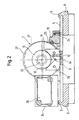
- a workpiece carrier 1 serves to receive a rotor or rotor 2 (FIG 2)
- the workpiece holder 1 has an essentially rectangular opening 3 in one Carrier plate 4 on
- the carrier plate 4 lies below the carrier plate 4 to the outer edges arranged on the carrier plate and upwards and towards the center of the carrier plate 4 indicative overhangs 5 bearing parts 6.
- the supporting parts 6 are screwed, welded, soldered or onto the support plate 4, for example otherwise connected to it, provided that it is made of steel or a like the support plate 4 other metal. Other materials are for the support plate 4 and the Support parts 6 replaceable.
- Receiving elements arranged in alignment with one another in the longitudinal direction of the carrier plate 4 7, 8 are preferably connected to the carrier plate 4 by means of screws 9, 10.
- Preferably 4 slots are provided in the support plate, which a shifting of Receiving elements 7, 8 in both directions on that formed by the carrier plate 4 Allow level
- the receiving elements 7, 8 have inclined surfaces 11, 12 on which an outer Bearing shell of a ball bearing 13 can be placed with its outer surface.
- the inclination the surfaces 11, 12 to each other are, for example, 90 °; come into consideration however other obtuse or acute angles.
- a groove 14 is provided through which the arrangement of the surfaces 11, 12 to each other at an obtuse or acute angle in their manufacture is facilitated
- the boundary plate 15 On one of the receiving elements 7, 8 there is a boundary plate 15 with a barrier 150 attached, the sliding of the runner 2 after this on the workpiece carrier 1 has been applied, prevented in the direction A
- the boundary plate 15 has preferably one against the direction A towards the surface of the workpiece carrier inclined surface 16 on its top, which causes the rotor 2 over the surface 16 slides down onto the surfaces 11, 12.
- the Boundary plate 15 with the receiving element a single component.
- the receiving elements 7, 8 also each point towards the center of the carrier plate 4 inclined surface 17, 18.
- the inclination of the surface 17 prevents that led out of the laminated core 27 of the rotor 2 on its end face Windings come to rest on surface 17.
- the area 18 achieves that the rotor 2 easily lay down on the surfaces 11, 12 with its ball bearing 13 leaves
- receiving blocks on the carrier plate 19, 20 provided, which are connected to the carrier plate 4 by means of screws 21, 22, 23, 24 are, preferably via elongated holes, the displaceability of the receiving blocks 19, 20 in both directions on the plane formed by the surface of the carrier plate 4 allow.
- the receiving blocks 19, 20 are arranged on the long sides of the opening 3 and each have a recess 25 or 26 pointing towards the opening 3, which continue in the carrier plate 4 so that the opening 3 has projections on both sides, the serve for gripping arms of a manipulator (not shown here) a laminated core 27 of the runner 2 coming from the top of the workpiece carrier 1 also from the bottom of the laminated core 27 can reach here.
- the receiving blocks 19, 20 have surfaces 28, 29 inclined towards the opening 3, into which in the longitudinal direction of the workpiece carrier 1, d. H. parallel to the long sides of the opening 3 extending, each a substantially circular segment-shaped cross section having grooves 30, 31 are arranged, the resilient, one essentially Circular cross-section bands 32 made of plastic, rubber or the like are arranged.
- the tapes 32 protrude towards the opening 3 on the inclined Surfaces 28, 29 out and carry the laminated core 27 (dashed line in Fig. 2), as long as the rotor 2 is not yet provided with the ball bearings 13. This will make one Shaft 33 of rotor 2 protected from damage.
- the shaft 33 is not on the Receiving elements 7, 8, but runs above the receiving elements 7, 8
- the ball bearings 13 which are independent of the series of rotors 2 to be manufactured always have the same distance or at least are within a small range of distances that are still wide of the receiving elements 7, 8 are receivable, so that the rotor 2 on the inclined surfaces 11, 12 of the receiving elements comes to rest (solid line in Fig. 2) and occupies a position 27 ', in which it holds the receiving block 19, 2 and in particular in this introduced band 32 no longer touches
- a supporting body 34 for receiving a transmitting or Receiving elements 35 are provided on the workpiece carrier 1 .
- the sending and receiving element is an active transponder, for example.
Landscapes
- Engineering & Computer Science (AREA)
- Manufacturing & Machinery (AREA)
- Power Engineering (AREA)
- Manufacture Of Motors, Generators (AREA)
Description
- Fig. 1
- eine Draufsicht auf einen Werkstücktrager und
- Fig. 2
- eine Seitenansicht des Werkstückträgers gemäß Fig. 1, auf den ein Läufer oder Rotor eines Elektromotors aufge-. legt ist, teilweise geschnitten.
Claims (15)
- Verfahren zum Herstellen eines Rotors (2) für einen Elektromotor aus einem eine Welle (33) und ein auf der Welle (33) aufgebrachtes Blechpaket (27) aufweisenden Läufer (2), der auf einem Werkstückträger (1) gelagert wird, dadurch gekennzeichnet, daß der Laufer (2) zunachst mit dem Blechpaket 27) mittels Aufnahmeblöcken (19. 20) auf dem Werkstückträger (1) gelagert wird, daß anschliessend der Läufer (2) mit Wicklungen und Isolierelementen versehen wird, daß Kugellager (13) beidseitig des Blechpakets (27) auf dem Laufer (2) aufgebracht werden und der Läufer (2) dann auf die Kugellager (13) aufnehmenden Aufnahmeelementen (7, 8) des Werkstückträgers (1) gelagert wird.
- Werkstücktrager (1) zur Aufnahme eines eine Welle (33) und auf der Welle (33) aufgebrachte Kugellager (13) aufweisenden Läufers (2) oder Rotors eines Elektromotors mittels Aufnahmeelementen (7, 8), die die Welle (33) in im wesentlichen waagrechter Lage getragen, dadurch gekennzeichnet, daß die Aufnahmeelemente (7, 8) zur Aufnahme von äußeren Lagerschalen von auf der Welle aufgebrachten Kugellagern (32) angepaßt sind.
- Werkstucktrager (1) nach Anspruch 2, dadurch gekennzeichnet, daß mindestens eine den Querschnitt der Welle (33) übergreifende Begrenzungsplatte (15) auf dem Werkstuckträger (1) angeordnet ist, die ein Verschieben der Welle (33) des von dem Werkstucktragers (1) mittels der Aufnahmeelemente (7, 8) aufgenommenen Laufers (2) verhindert.
- Werkstücktrager (2) nach Anspruch 3, dadurch gekennzeichnet, daß die Begrenzungsplatte (15) mit einem der Aufnahmeelemente (7, 8) verbunden ist oder mit diesem ein einziges Bauteil bildet.
- Werkstücktrager (1) nach einem der Ansprüche 2 bis 4, dadurch gekennzeichnet, daß die Aufnahmeelemente (7, 8) in Quer- und/oder Längsrichtung auf einer Trägerplatte (4) des Werkstücktragers (1) verschieblich ausgebildet sind.
- Werkstucktrager (1) nach einem der Anspruche 2 bis 5, dadurch gekennzeichnet, daß die Aufnahmeelemente (7, 8) zu der Trägerfläche (4) geneigte Flächen (11, 12) aufweisen.
- Werkstucktrager (1) nach Anspruch 6, dadurch gekennzeichnet, daß die Flachen (11 12) unter einem Winkel von 90° zueinander geneigt sind.
- Werkstückträger (1) nach einem der Ansprüche 2 bis 7, dadurch gekennzeichnet, daß er Aufnahmeblöcke (19, 20) zur Aufnahme eines auf der Welle (33) aufgebrachten Blechpakets (27) des Läufers (2) aufweist.
- Werkstucktrager (1) nach Anspruch 7, dadurch gekennzeichnet, daß die Aufnahmeblocke (19. 20) parallel zu den Langsseiten einer in der Tragerplatte (4) angebrachten Öffnung (3) angeordnet sind.
- Werkstucktrager (1) nach Anspruch 6 oder 7, dadurch gekennzeichnet, daß die Aufnahmeblocke (19, 20) zu der Öffnung (3) hinweisende Ausnehmungen (25, 26) haben
- Werkstucktrager (1) nach einem der Ansprüche 6 bis 8, dadurch gekennzeichnet, daß die Aufnahmeblöcke (19, 20) zu der Öffnung (3) hin geneigte Flächen (16, 17) haben
- Werkstucktrager (1) nach Anspruch 8 oder 9, dadurch gekennzeichnet, daß in den Aufnahmeblöcken (19, 20) jeweils eine Nut (30, 31) zur Aufnahme eines Bandes (32) aus einem elastisch federnden Material vorgesehen ist, welches aus den Aufnahmeblöcken und oben und/oder zu der Öffnung (3) hin herausragt.
- Werkstückträger (1) nach Anspruch 12, dadurch gekennzeichnet, daß das elastisch federnde Material ein Kunststoff ist
- Werkstucktrager (1) nach Anspruch 12 oder 13, dadurch gekennzeichnet, daß die Bander (32) einen kreisförmigen Querschnitt haben.
- Werkstücktrager (1) nach einem der Anspruche 8 bis 12, dadurch gekennzeichnet, daß die Aufnahmeblöcke (19, 20) in Quer- und/oder Langsnchtung des Werkstucktragers (1) verschieblich angeordnet sind.
Applications Claiming Priority (3)
| Application Number | Priority Date | Filing Date | Title |
|---|---|---|---|
| DE1999160308 DE19960308A1 (de) | 1999-12-14 | 1999-12-14 | Verfahren zum Herstellen eines Rotors für einen Elektromotor und Werkstückträger zur Durchführung des Verfahrens |
| DE19960308 | 1999-12-14 | ||
| PCT/EP2000/012300 WO2001045234A1 (de) | 1999-12-14 | 2000-12-06 | Verfahren zum herstellen eines rotors für einen elektromotor und werkstückträger zur durchführung des verfahrens |
Publications (2)
| Publication Number | Publication Date |
|---|---|
| EP1245071A1 EP1245071A1 (de) | 2002-10-02 |
| EP1245071B1 true EP1245071B1 (de) | 2004-08-04 |
Family
ID=7932641
Family Applications (1)
| Application Number | Title | Priority Date | Filing Date |
|---|---|---|---|
| EP00993467A Expired - Lifetime EP1245071B1 (de) | 1999-12-14 | 2000-12-06 | Verfahren zum herstellen eines rotors für einen elektromotor und werkstückträger zur durchführung des verfahrens |
Country Status (4)
| Country | Link |
|---|---|
| EP (1) | EP1245071B1 (de) |
| DE (1) | DE19960308A1 (de) |
| SK (1) | SK8222002A3 (de) |
| WO (1) | WO2001045234A1 (de) |
Families Citing this family (1)
| Publication number | Priority date | Publication date | Assignee | Title |
|---|---|---|---|---|
| US10274126B2 (en) | 2016-06-14 | 2019-04-30 | Siemens Energy, Inc. | System and method for servicing rotor of generator using universal support device |
Family Cites Families (6)
| Publication number | Priority date | Publication date | Assignee | Title |
|---|---|---|---|---|
| IT1223829B (it) * | 1988-09-16 | 1990-09-29 | Axis Spa | Linea per la lavorazione di indotti di diverso tipo |
| US5060780A (en) * | 1989-03-20 | 1991-10-29 | Axis U.S.A., Inc. | Pallets for supporting workpieces and automatic adjustment of pallet workpiece support members |
| US5348142A (en) * | 1993-07-26 | 1994-09-20 | Odawara Engineering Co., Ltd. | Adjustable pallet |
| US5685413A (en) * | 1995-09-12 | 1997-11-11 | Odawara Automation, Inc. | Adjustable pallet for supporting work pieces |
| US5926941A (en) * | 1996-07-23 | 1999-07-27 | Axis Usa, Inc. | Armature pallet |
| US5735219A (en) * | 1996-11-27 | 1998-04-07 | Odawara Automation, Inc. | Open base adjustable pallet for supporting work pieces |
-
1999
- 1999-12-14 DE DE1999160308 patent/DE19960308A1/de not_active Withdrawn
-
2000
- 2000-12-06 WO PCT/EP2000/012300 patent/WO2001045234A1/de not_active Ceased
- 2000-12-06 SK SK822-2002A patent/SK8222002A3/sk unknown
- 2000-12-06 EP EP00993467A patent/EP1245071B1/de not_active Expired - Lifetime
Also Published As
| Publication number | Publication date |
|---|---|
| DE19960308A1 (de) | 2001-06-21 |
| WO2001045234A1 (de) | 2001-06-21 |
| SK8222002A3 (en) | 2002-11-06 |
| EP1245071A1 (de) | 2002-10-02 |
Similar Documents
| Publication | Publication Date | Title |
|---|---|---|
| DE60306966T2 (de) | Rotierende elektrische Fahrzeugmaschine | |
| EP0885083B1 (de) | Verfahren zum zerteilen von blöcken aus harten werkstoffen in platten mittels einer drahtsäge und drahtsäge zur durchführung dieses verfahrens | |
| EP1073181A1 (de) | Rotierende elektrische Maschine und Verfahren zu deren Herstellung | |
| DE69115232T2 (de) | Anker in einem elektrischen motor. | |
| DE102008060896B4 (de) | Spulentragvorrichtung | |
| WO2012098205A2 (de) | Verfahren zum herstellen von vorverzinnten verbindern für pv-zellen und metallfolie mit in einer richtung verlaufender rillenstruktur | |
| DE1948024A1 (de) | Laeufer fuer elektrische Maschinen | |
| DE19909617A1 (de) | Zahnförderriemen und eine Schichtentfernungsvorrichtung für den Zahnförderriemen | |
| CH638418A5 (de) | Verfahren zum herstellen eines saegedrahtpaketes. | |
| WO2014114541A1 (de) | Vorrichtung zum verbinden von aufeinanderfolgend in eine bandbehandlungsanlage einlaufenden metallflachprodukten | |
| DE1765027B1 (de) | Vorrichtung zum elektrischen verbinden der einander ent sprechenden draehte zweier drahtpaare | |
| WO2007065532A1 (de) | Kennzeichnungsschildersatz | |
| EP1245071A1 (de) | Verfahren zum herstellen eines rotors für einen elektromotor und werkstückträger zur durchführung des verfahrens | |
| DE3933316C2 (de) | ||
| EP3544160B1 (de) | Transportsystem für wellenwickelmatten | |
| DE102005033859B3 (de) | Wafermagazin für Halbleiterwafer oder waferartige Gegenstände | |
| DE69111513T2 (de) | Halbleiterherstellungseinrichtung. | |
| DE69715990T2 (de) | Palette für Motoranker | |
| DE19519839A1 (de) | Vorrichtung zum Stanzschneiden von Metallbändern in Streifen | |
| DE29519805U1 (de) | Transfereinrichtung für Fördergut | |
| DE2926506C2 (de) | Verfahren zur Herstellung eines gehäuselosen Elektromotors mit einer einzigen Schutzleiteranschluß-Klemme | |
| DE102004008567B4 (de) | Vorrichtung und Verfahren zum Herstellen eines in einer Ebene mehrere Segmente aufweisenden ringförmigen Bauteils | |
| DE102010031552A1 (de) | Verfahren und Vorrichtung zum Herstellen eines ringförmigen Maschinenelements, insbesondere zum Einsatz in einer elektrischen Maschine | |
| DE4411482A1 (de) | Schrägstehender Schneid-Klemm-Kontakt | |
| DE19931172C1 (de) | Vorrichtung zum Separieren von nebeneinander liegend geförderten, insbesondere aus Metall bestehenden Streifen |
Legal Events
| Date | Code | Title | Description |
|---|---|---|---|
| PUAI | Public reference made under article 153(3) epc to a published international application that has entered the european phase |
Free format text: ORIGINAL CODE: 0009012 |
|
| 17P | Request for examination filed |
Effective date: 20020715 |
|
| AK | Designated contracting states |
Kind code of ref document: A1 Designated state(s): AT BE CH CY DE DK ES FI FR GB GR IE IT LI LU MC NL PT SE TR |
|
| GRAP | Despatch of communication of intention to grant a patent |
Free format text: ORIGINAL CODE: EPIDOSNIGR1 |
|
| RAP1 | Party data changed (applicant data changed or rights of an application transferred) |
Owner name: BSH BOSCH UND SIEMENS HAUSGERAETE GMBH |
|
| REG | Reference to a national code |
Ref country code: DE Ref legal event code: 8566 |
|
| GRAS | Grant fee paid |
Free format text: ORIGINAL CODE: EPIDOSNIGR3 |
|
| GRAA | (expected) grant |
Free format text: ORIGINAL CODE: 0009210 |
|
| AK | Designated contracting states |
Kind code of ref document: B1 Designated state(s): IT |
|
| REG | Reference to a national code |
Ref country code: IE Ref legal event code: FG4D Free format text: GERMAN |
|
| REG | Reference to a national code |
Ref country code: IE Ref legal event code: FD4D |
|
| PLBE | No opposition filed within time limit |
Free format text: ORIGINAL CODE: 0009261 |
|
| STAA | Information on the status of an ep patent application or granted ep patent |
Free format text: STATUS: NO OPPOSITION FILED WITHIN TIME LIMIT |
|
| 26N | No opposition filed |
Effective date: 20050506 |
|
| PGFP | Annual fee paid to national office [announced via postgrant information from national office to epo] |
Ref country code: IT Payment date: 20081224 Year of fee payment: 9 |
|
| PG25 | Lapsed in a contracting state [announced via postgrant information from national office to epo] |
Ref country code: IT Free format text: LAPSE BECAUSE OF NON-PAYMENT OF DUE FEES Effective date: 20091206 |