TECHNICAL FIELD
The present invention relates to the improvement of a plate fin heat
exchanger for a high temperature, for example, conducting heat exchange
between combustion exhaust gases and the air. More specifically, the present
invention relates to a plate fin heat exchanger for a high temperature with a
structure in which elements obtained by soldering fins to both tube plate
surfaces of the channel for low-temperature air are stacked and arranged via
spacer bars and in which a tubular duct for high-temperature fluid can be used
by itself as a heat exchanger container, this heat exchanger demonstrating
excellent endurance and high heat exchange efficiency when used under severe
conditions, for example, as a regenerator of a micro gas turbine power
generator.
BACKGROUND ART
Micro gas turbine power generators have recently attracted attention
and found practical use as emergency private power generators or medium-and
small-scale distributed power sources. Gas turbines have a structure
simpler than that of other internal combustion engines, can be produced on a
mass scale, are easy to maintain and inspect, and operate at a low NOx level.
Micro gas turbine power generators of the next generation typically
employ a structure of a single-shaft regeneration cycle gas turbine to improve
the total power generation efficiency.
Thus, in such power generators, a compressor, a turbine, and a generator
are arranged on one shaft, combustion gases from a combustion chamber rotate
the turbine, and then heat exchange is conducted in a heat exchanger with the
air that passed the compressor. The power generators of this type decrease,
even if to a small degree, the loss of combustion gas energy and have a thermal
conversion efficiency equal to, or better than that of conventional power
generators employing diesel engines.
With the single-shaft regeneration cycle gas turbine, low-NOx exhaust
gases are obtained with lean-mixture combustion, and using plate fin heat
exchanger makes it possible to increase the heat exchange efficiency to about
90%.
On the other hand, micro gas turbine power generators are required to
endure a large number of start/stop cycles and also to have the improved
operation start-up characteristic immediately after they are turned on and to
supply immediately the necessary power. This requirement is obvious for
emergency situations, but is also valid for applications of such power
generators as distributed power sources.
Therefore, plate fin heat exchangers used for heat exchange between
combustion gases and compressed air are required to demonstrate an excellent
heat exchange efficiency and to retain the attained heat exchange efficiency,
while maintaining endurance sufficient to withstand vary intense heat input,
in particular non-uniform temperature distribution inside the fluid channels
and extreme variations of thermal load.
DISCLOSURE OF THE INVENTION
It is an object of the present invention to provide a plate fin heat
exchanger capable of demonstrating the above-described performance required
for plate fin heat exchangers for heat regeneration in micro gas power
generators, that is, high endurance and heat exchange efficiency under
extreme variations of thermal load, such a heat exchanger having a structure
perfectly suitable for mass production.
It is another object of the present invention to provide a plate fin heat
exchanger with a structure such that heat exchangers can be arranged in
series so that waste heat recovery can be conducted separately at the
downstream side of the regenerator.
The inventors have conducted a comprehensive study of structures
making it possible to lessen thermal stresses in plate fin heat exchangers, for
example, caused by non-uniform temperature distribution inside fluid
channels and in the entire apparatus occurring when high-temperature
combustion gas flows therein. The results obtained demonstrated that usually
all of the fins located inside the high-temperature channels were soldered to
low-temperature channels, but as shown in Fig. 1B, making all of the fins
located inside the high-temperature channels independent for each low-temperature
channels, rather than soldering them, lessened thermal stresses,
greatly increased the endurance and also allowed for a transition to a modular
structure, reduced the number of soldering operations, and increased mass
productivity.
The inventors have also found that using non-directional distributors
containing no corrugation fins and the like in the low-temperature channels in
the above-described structure makes it possible to prevent one-side flow in the
heat exchange unit, and that appropriately providing a shielding cover on the
front surface of the low-temperature channel facing the inlet opening of high-temperature
channel additionally increases endurance, without exposing the
soldered portions of low-temperature channel to high-temperature fluid.
Thus, the first invention provides a plate fin heat exchanger for a high
temperature, in which channels for low-temperature fluid and channels for
high-temperature fluid are disposed in stacks and form a core independently
for each channel for low-temperature fluid. For example, considering a
structure in which the fins forming a channel for high-temperature fluid are
fixed to at least one of a pair of tube plates forming the channels for low-temperature
fluid as an element and forming a core by disposing a plurality of
such elements inside a container such as a duct for high-temperature fluid
makes it possible to provide plate fin heat exchangers with highly durable
structure for high temperature, such heat exchangers being suitable for mass
production.
The inventors have conducted a comprehensive study of structures that
are easy to manufacture and have found that the assembling operation can be
greatly facilitated if, as shown in FIG. 4, core assembly elements are produced
by decreasing the size of fins located inside the high-temperature channels,
fixing them to the low-temperature channel, and arranging small spacer bars
in places where no fins are provided, and if those elements are assembled by
stacking conducted, for example, by seal welding the spacer bars to each other.
Thus, the second invention relates to a plate fin heat exchanger for a
high temperature with a structure in which channels for low-temperature fluid
and channels for high-temperature fluid are disposed in stacks and form a core
independently for each channel for low-temperature fluid by using core
assembly elements in which spacer bars and fins forming the channels for
high-temperature fluid are fixed to at least one of a pair of tube plates forming
the channels for low-temperature fluid.
The inventors have also discovered that in a plate fin heat exchanger
with the above-described structure in which a tubular duct for high-temperature
fluid serves by itself as a heat exchanger container, if the duct for
high-temperature fluid is extended and the respective separate plate fin heat
exchangers or tube-type heat exchangers are disposed upstream and
downstream of the high-temperature fluid, then a heat exchange system with a
very good heat recovery efficiency can be constructed in which waste heat
recovery can be conducted, for example, by using the upstream heat exchanger
as a regenerator in a micro gas turbine power generator and using the
downstream heat exchanger as a steam and/or hot water generator.
Thus, the third invention relates to a plate fin heat exchanger for a high
temperature, in which a tubular duct for high-temperature fluid serves by
itself as a heat exchanger container and channels for low-temperature fluid
and channels for high-temperature fluid are disposed in stacks and form a core
independently for each channel for low-temperature fluid by using core
assembly elements in which fins forming the channels for high-temperature
fluid, and optionally space bars, are fixed to at least one of a pair of tube plates
forming the channels for low-temperature fluid, wherein at least one separate
heat exchanger conducting heat exchange with high-temperature fluid is
additionally disposed downstream of the heat exchangers located inside the
duct.
Further, the inventors have assumed a double-wall tubular system
structure in which heat exchangers are disposed in a ring-like fashion on the
outer periphery of a turbine in a micro gas turbine power generator and are
used as regenerators conducting heat exchange by causing the exhaust gases
from the turbine to make a U turn and have conducted a comprehensive study
of effective arrangement of the above-described core units.
The results obtained demonstrated that if a cylindrical duct for high-temperature
fluid is used as a heat exchanger container and also as an outer
tube, a plurality of the core units with the above-described structure are
radially disposed between the inner tube of the turbine and the duct, and the
inlet and outlet header tanks of low-temperature fluid are cantilever disposed
on the cylindrical duct on the outer periphery or on the inner tube of the
turbine, then a system with a very good heat recovery efficiency can be
constructed which can demonstrate high durability and heat exchange
efficiency under rapid changes of thermal load, for example, when the gas
turbine is turned on or off. This finding led to the present invention.
Thus, the fourth invention relates to a plate fin heat exchanger for a
high temperature, in which a plurality of core units are disposed radially inside
a cylindrical body serving as a channel for high-temperature fluid or between a
cylindrical body and an inner tube arranged inside the cylindrical body, those
core units being formed by disposing channels for low-temperature fluid and
channels for high-temperature fluid in stacks independently for each channel
for low-temperature fluid by using core assembly elements in which fins
forming the channels for high-temperature fluid, and optionally spacer bars,
are fixed to at least one of a pair of tube plates forming the channels for low-temperature
fluid, wherein
BRIEF DESCRIPTION OF THE DRAWINGS
FIG. 1A is a perspective view illustrating an example of the plate fin
heat exchanger for a high temperature in accordance with the present
invention. FIG. 1B is a perspective view illustrating the external appearance of
a low-temperature fluid channel; only part of the fins is shown.
FIG. 2 is a disassembled view of the low-temperature fluid channel. FIG.
2A shows a tube plate and FIG. 2B shows a channel body.
FIG. 3A is longitudinal section of the structure shown in FIG. 1A, and
FIG. 3B illustrates the inlet and outlet openings of a low-temperature fluid
channel;
FIG. 4 is a perspective view illustrating an example of a core of the plate
fin heat exchanger for a high temperature in accordance with the present
invention;
FIG. 5 is a perspective view illustrating an example of the plate fin heat
exchanger for a high temperature in accordance with the present invention;
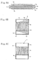
FIG. 6A is a central cross-sectional vie of the assembly unit using a low-temperature
fluid channel as the base component. FIG. 6B is an inner view of
the low-temperature fluid channel of the assembly unit. FIG. 6C is a top
surface view of the assembly unit;
FIG. 7 is a perspective view illustrating a structure example of the plate
fin heat exchanger for a high temperature in accordance with the present
invention;
FIG. 8 illustrates another structure example of the rear-stage heat
exchanger; and
FIGS. 9A, 9C are plan views illustrating structure examples of the plate
fin heat exchanger for a high temperature in accordance with the present
invention. FIGS. 9B, 9D are longitudinal sectional views of main portions of
the structures shown in FIGS. 9A, 9C, respectively.
BEST MODE FOR CARRYING OUT THE INVENTION
Structure Example 1
An example of the structure of the plate fin heat exchanger for a high
temperature in accordance with the present invention will be explained below
with reference to FIGS. 1 to 3. The example shown in FIG. 1A relates to
counter-flow heat exchange between a high-temperature fluid and a low-temperature
fluid. As shown in the figure, the high-temperature fluid H passes
through a core 2 of a heat exchanger 1 from the front to the rear part thereof,
whereas the low-temperature fluid L flows into the heat exchanger 1 through
the side surface in the rear part thereof and flows out from the side surface in
the front part thereof.
The core 2 of heat exchanger 1 has a structure in which high-temperature
fluid channels 4 and low-temperature fluid channels 5 are stacked
alternately inside a container 3.
The low-temperature fluid channel 5, as shown in FIG. 1B and FIG. 2,
has a configuration in which a corrugation fin 5b is sandwiched between two
tube plates 5a, 5a and those components are brazed and integrated so that the
peripheral portions are closed with spacer bars 5c. A spacer bar 5d on one end
surface side is made short to form a fluid inlet opening 6 and a fluid outlet
opening 7 and fluid distributor portions 5e, 5f serve as non-directional
distributors having no fins disposed therein.
Furthermore, corrugation fins 4a, 4b are brazed to respective outer
surfaces of the two tube plates 5a, 5a of low-temperature fluid channel 5. The
above-described low-temperature fluid channels 5 are disposed with the
prescribed spacing inside the container 3 containing the core 2 of heat
exchanger 1. As a result, high-temperature fluid channels 4 are formed by the
corrugation fins 4a, 4b.
Thus, as shown in FIG. 3, the fluid inlet openings 6 and outlet openings 7
of low-temperature fluid channels 5 are cantilever supported on the side
surface of the box-like container 3, and the low-temperature fluid channels 5
are disposed inside the container 3 at a spacing preventing the corrugation fins
4a, 4b from abutting each other.
For example, when the high-temperature fluid H rapidly flows into the
plate fin heat exchanger for a high temperature in accordance with the present
invention, which has the above-described structure, the side of container 3
where the inlet openings of high-temperature fluid channels 4 are located is
intensely heated. The high-temperature fluid channels 4 are formed by
corrugation fins 4a, 4b provided on the outer surface of low-temperature fluid
channels 5. Those fins are not restricted inside the high-temperature fluid
channels 4 and even when they are intensely heated, they do not accumulate
thermal stresses and can effectively conduct the heat of high-temperature fluid
H into the low-temperature fluid channels 5.
Furthermore, inside the low-temperature fluid channels 5, the low-temperature
fluid L flowing in from a non-directional distributor portion 5e
can participate in counter-flow heat exchange with the high-temperature fluid
H, without a drift flow, and can flow out via the non-directional distributor
portion 5f from the fluid outlet opening 7 after being heated to a high
temperature. In this case, though the corrugation fins 4a, 4b of high-temperature
fluid channels 4 are exposed to a high temperature, thermal
stresses are not accumulated in the low-temperature fluid channel 5.
Furthermore, intense heating of the low-temperature fluid channels 5
themselves also causes no accumulation of thermal stresses because of the
cantilever support structure.
In the constitution of distributor portions 5e, 5f of low-temperature fluid
channels 5, the rigidity of distributor portions 5e, 5f can be increased by using a
structure in which the tube plates are provided with dimples and protruding
portions of the dimples are abutted against and joined to each other inside the
channels.
Structure Example 2
Another example of the structure of the plate fin heat exchanger for a
high temperature in accordance with the present invention will be explained
below with reference to FIGS. 4 to 6. The example shown in FIG. 4 relates to
counter-flow heat exchange between a high-temperature fluid and a low-temperature
fluid. As shown in the figure, the high-temperature fluid H passes
through a core 2 of heat exchanger 1 from the front to the rear part thereof,
whereas the low-temperature fluid L flows into the heat exchanger 1 through
the side surface in the rear part thereof and flows out from the side surface in
the front part thereof.
The core 2 of heat exchanger 1 has a structure in which high-temperature
fluid channels 4 and low-temperature fluid channels 5 are stacked
alternately inside a container 3. The low-temperature fluid channel 5, as
shown in FIG. 5 and FIG. 6, has a configuration in which a corrugation fin 5b is
sandwiched between two tube plates 5a, 5a and those components are brazed
and integrated so that the peripheral portions are closed with spacer bars 5c.
A spacer bar 5d on one end surface side is made short to form a fluid inlet
opening 6 and a fluid outlet opening 7, and triangular fins are disposed in the
fluid distributor portions 5e, 5f to form distribution channels.
Furthermore, corrugation fins 4a, 4b are brazed to respective outer
surfaces of the two tube plates 5a, 5a of low-temperature fluid channel 5. The
corrugation fins 4a, 4b are disposed in the positions facing the corrugation fins
5g which are the main fin components, except the distributor portions 5e, 5f
located inside the low-temperature fluid channel 5, and short spacer bars 4b
are fixed in four places mainly serving as the end portions of respective
positions of distributor portions 5e, 5f.
By using elements for a core assembly based on the low-temperature
fluid channels 5 of the above-described configuration, it is possible to stack and
dispose the low-temperature fluid channels 5 inside the container 3 containing
the core 2 of heat exchanger 1, with the prescribed spacing by using the spacer
bars 4b abutted above and below thereof. The corrugation fins 4a, 4b provided
opposite each other on the low- temperature fluid channels 5, 5 positioned above
and below thereof form the high-temperature fluid channels 4. The spacer bars
4b on the right side surface, as shown in the figure, are seal welded to each
other, and the spacer bars 4b on the left side, as shown in the figure, are not
fixed.
Furthermore, the fluid inlet openings 6 and outlet openings 7 of low-temperature
fluid channels 5 are cantilever supported, being secured only to
the right side surface of the box-like container 3, as shown in the figure, and
the spacer bar 4b side on the left side, as shown in the figure, is not fixed.
Furthermore, low-temperature fluid channels 5 are disposed inside the
container 3 at a spacing preventing the corrugation fins 4a, 4b from abutting
each other. Header tanks (not shown in the figure) are fixedly disposed in the
fluid inlet opening 6 and outlet opening 7 of container 3.
For example, when the high-temperature fluid H rapidly flows into the
plate fin heat exchanger for a high temperature in accordance with the present
invention, which has the above-described structure, the side of container 3
where the inlet openings of high-temperature fluid channels 4 are located is
intensely heated. The high-temperature fluid channels 4 are formed by
corrugation fins 4a, 4b provided in the central portion of the outer surface of
low-temperature fluid channels 5. Those fins are not restricted inside the high-temperature
fluid channels 4 and even when they are intensely heated, they do
not accumulate thermal stresses and can effectively conduct the heat of high-temperature
fluid H into the low-temperature fluid channels 5.
Furthermore, inside the low-temperature fluid channels 5, the low-temperature
fluid L flowing in from a distributor portion 5e can participate in
counter-flow heat exchange with the high-temperature fluid H, without a drift
flow, and can flow out via the non-directional distributor portion 5f from the
fluid outlet opening 7 after being heated to a high temperature. In this case,
the corrugation fins 4a, 4b of high-temperature fluid channels 4 are not located
in the positions corresponding to the distributor portions 5e, 5f, and even if
they are exposed to a high temperature, thermal stresses are not accumulated
in the low-temperature fluid channel 5. Furthermore, intense heating of the
low-temperature fluid channels 5 themselves also causes no accumulation of
thermal stresses because of the cantilever support structure.
Furthermore, the intense heat input observed when the high-temperature
fluid H flows in at a high speed can be relieved by attaching
shielding covers of various types to the front surface of the low-temperature
fluid channel 5 facing the inlet opening of high-temperature fluid channel 4 in
the above-described Structure Example 1 and Structure Example 2. Various
means can be used for this purpose. For example, a louver member also serving
as a flow adjusting component can be attached, or a thermal insulating
member can be attached, or the tube plate of low-temperature fluid channel 5
can be extended and bent.
In accordance with the present invention, means for making the low-temperature
fluid channels independent from each other can have a variety of
structures other than the above-one structures. Thus, a structure in which
corrugation fins are provided only on one surface of low-temperature fluid
channels, a structure with cross-flow heat exchange, and a structure in which
the duct of the high-temperature fluid serves by itself as the heat exchanger
can be used.
In accordance with the present invention, in addition to the above-described
alternate disposition of channels, a variety of other dispositions, for
example, a combination of counter flow and cross flow, can be employed for
stacking the low-temperature fluid channels and high-temperature fluid
channels in the core, and the specific disposition can be appropriately selected
according to the type of fluid or temperature.
In accordance with the present invention, no limitation is placed on the
material of heat exchanger. However, if heat resistance is required, then well-known
Fe-based, Ni-based, or Co-based heat-resistance alloys can be used.
Moreover, austenitic heat-resistance steels, Co3Ti, Ni3Al, and stainless steels
with an Al content of no more than 10 wt.% can be used. The same is true for
the below-described structure examples.
Structure Example 3
Another example of the structure of the plate fin heat exchanger for a
high temperature in accordance with the present invention will be explained
below with reference to FIGS. 7 and 8. This example relates to counter-flow
heat exchange between a high-temperature fluid H and a low-temperature
fluid. As shown in FIG. 1A, the high-temperature fluid H passes through a core
2 of heat exchanger 1, the side of heat exchanger 1 which is upstream of high-temperature
fluid H is a pre-stage heat exchanger 1a, the downstream side is a
post-stage heat exchanger 1b, and heat exchange is conducted in two stages.
Furthermore, the rear-stage heat exchanger 1b constitutes separate
heat exchangers 1b1, 1b2 on the upper and lower side. In the figure, the length
of post-stage heat exchanger 1b is represented to be equal to that of front-side
heat exchanger 1a, but it can obviously be appropriately selected, for example,
to be less or more depending of specifications of heat exchangers and required
performance.
The pre-stage heat exchanger 1a positioned upstream of heat exchanger
1 has a structure such that a low-temperature fluid L, which is composed of the
air, flows in from the rear side surface of pre-stage heat exchanger 1a and flows
out from the side surface in the front side thereof, with respect to a high-temperature
fluid H, such as high-temperature exhaust gases, flowing from the
front to the rear portion.
The core 2 of pre-stage heat exchanger 1a has a structure in which the
high-temperature fluid channels 4 and low-temperature fluid channels 5 are
stacked alternately inside the container 3, as shown in FIG. 5. The low-temperature
fluid channel 5, as shown in FIG. 6, has a configuration such that
a corrugation fin 5g is sandwiched between two tube plates 5a, 5a, and those
components are brazed and integrated so that the peripheral portions are
closed with spacer bars 5c.
A spacer bar 5d on one end surface side is made short to form a fluid inlet
opening 6 and a fluid outlet opening 7 and triangular fins are disposed in the
fluid distributor portions 5e, 5f to form distribution channels.
Furthermore, corrugation fins 4a, 4b are brazed to respective outer
surfaces of the two tube plates 5a, 5a of low-temperature fluid channel 5. The
corrugation fins 4a, 4b are disposed in the positions facing the main fin
components 5g, except the distributor portions 5e, 5f located inside the low-temperature
fluid channel 5, and short spacer bars 4c are fixed in four places
mainly serving as the end portions of respective positions of distributor
portions 5e, 5f.
By using elements for a core assembly based on the low-temperature
fluid channels 5 of the above-described configuration, it is possible to stack and
dispose the low-temperature fluid channels 5 inside the container 3 containing
the core 2 of pre-stage heat exchanger 1a, with the prescribed spacing by using
the spacer bars 4c abutted above and below thereof. The corrugation fins 4a, 4a
provided opposite each other on the low- temperature fluid channels 5,5
positioned above and below thereof form the high-temperature fluid channels
4. The spacer bars 4c on the right side surface, as shown in the figure, are seal
welded to each other, and the spacer bars 4c on the left side, as shown in the
figure, are not fixed.
Furthermore, the fluid inlet openings 6 and outlet openings 7 of low-temperature
fluid channels 5 are cantilever supported, being secured only to
the right side surface of the box-like container 3, as shown in the figure, and
the spacer bar 4 side on the left side, as shown in the figure, is not fixed.
Furthermore, low-temperature fluid channels 5 are disposed inside the
container 3 at a spacing preventing the corrugation fins 4a, 4b from abutting
each other. Header tanks (not shown in the figure) are fixedly disposed in the
fluid inlet opening 6 and outlet opening 7 of container 3.
For example, when the high-temperature fluid H rapidly flows into the
plate fin heat exchanger 1a for high temperature in accordance with the
present invention, which has the above-described structure, the side of
container 3 where the inlet openings of high-temperature fluid channels 4 are
located is intensely heated. The high-temperature fluid channels 4 are formed
by corrugation fins 4a, 4a provided in the central portion of the outer surface of
low-temperature fluid channels 5. Those fins are not restricted inside the high-temperature
fluid channels 4 and even when they are intensely heated, they do
not accumulate thermal stresses and can effectively conduct the heat of high-temperature
fluid H to the low-temperature fluid channels 5.
Furthermore, inside the low-temperature fluid channels 5, the low-temperature
fluid L flowing in from a distributor portion 5e can participate in
counter-flow heat exchange with the high-temperature fluid H, without a drift
flow, and can flow out via the non-directional distributor portion 5f from the
fluid outlet opening 7 after being heated to a high temperature. In this case,
the corrugation fins 4a, 4a of high-temperature fluid channels 4 are not located
in the positions corresponding to the distributor portions 5e, 5f, and even if
they are exposed to a high temperature, thermal stresses are not accumulated
in the low-temperature fluid channel 5. Furthermore, intense heating of the
low-temperature fluid channels 5 themselves also causes no accumulation of
thermal stresses because of the cantilever support structure.
The rear-stage heat exchanger 1b basically has the same structure as
the above-described pre-stage heat exchanger 1a and constitutes separate heat
exchangers 1b1, 1b2 on the upper and lower side. Thus, the plate fin heat
exchangers for a high temperature of the above-described structure shown in
FIG. 2 have a common container 3, are connected in series in the direction of
high-temperature fluid flow and form an upstream pre-stage heat exchanger
1a and a downstream rear-stage heat exchanger 1b. The inlet and outlet
openings for fluid of the rear-stage heat exchanger can be further divided in the
vertical direction, providing for inlet and outlet of separate fluids and forming
separate heat exchangers 1b1, 1b2 on the upper and lower side.
For example, a large amount of water can be introduced as a low-temperature
fluid L1 into the upper heat exchanger 1b1 of rear-stage heat
exchanger 1b and a hot-water at the prescribed temperature can be taken out.
Moreover, a small amount of water can be introduced as a low-temperature
fluid L2 into the lower heat exchanger 1b2 and steam can be taken out.
The rear-stage heat exchanger 1b is divided in two in the width direction
of container 3, as shown in FIG. 8, by using a cantilever structure, shown in
FIG 1, forming separate heat exchangers, namely, a right heat exchanger and
a left heat exchanger supported on respective side surfaces of container 3, and
the respective different low-temperature fluid L1 and low-temperature fluid L2
can be introduced and taken out.
Furthermore, a structure can be also employed in which a switchable
outlet damper 8 is provided on the downstream end of container 3, making it
possible to select a heat exchanger through which a high-temperature fluid H
is passed. With such a structure, in the above-described example, either hot
water or steam can be selectively taken out.
With any of the above-described structures, even if the rear-stage heat
exchanger 1b is exposed to a high temperature, thermal stresses are not
accumulated in the low-temperature fluid channels 5, and intense heating of
the low-temperature fluid channels 5 themselves also causes no accumulation
of thermal stresses because of the cantilever support structure.
The rear-stage heat exchangers 1b can be arranged not only in one stage
with the separation into upper and lower heat exchangers, but also in a
multistage series. Therefore, a plurality of heat exchanges can be conducted till
the temperature of high-temperature fluid drops to the prescribed
temperature.
In the above-described example, a fin-plate heat exchanger with a
cantilever structure identical to that of the pre-stage heat exchangers was used
for the rear-stage heat exchanger 1b. However, heat exchangers of a variety of
conventional structures, such as plate fin heat exchangers or tubular heat
exchangers, can be selected and appropriately disposed in a common container
3 according to the required performance or specifications.
Structure Example 4
An example of the structure of the plate fin heat exchanger for a high
temperature in accordance with the present invention will be explained below
with reference to FIG. 9. This example relates to counter-flow heat exchange
between a high-temperature fluid H flowing inside a large-diameter
cylindrical body 10 and a low-temperature fluid L introduced into the heat
exchanger 1.
As shown in FIGS. 9A, B, eight heat exchangers 1 are disposed radially
along the inner peripheral surface of the large-diameter cylindrical body 10.
Each heat exchanger 1 is cantilever supported on the large-diameter
cylindrical body 10 and has a structure such that the header tank 11 of low-temperature
fluid L is provided in the support zone.
The heat exchangers 1 disposed radially along the inner peripheral
surface of the large-diameter cylindrical body 10 can be arranged so that the
heat exchangers with a large length in the radial direction of large-diameter
cylindrical body 10 will alternate with those with a small length, so that the
heat exchangers will contact each other at the non-supported end surface
thereof. In the present configuration, however, the heat exchangers of the same
required length are selected and a hollow zone 12 is provided in the central
portion of large-diameter cylindrical body 10.
Other devices or other fluid channels can be disposed in the hollow zone
12. For example, in a micro gas turbine power generator, an inner tube 13 is
disposed and a gas turbine is arranged inside thereof. In such a structure
example, the high-temperature fluid H is exhaust gases, and the low-temperature
fluid L is the air.
Furthermore, as shown in FIG. 9C, D, when eight heat exchangers 1 are
disposed radially along the inner peripheral surface of the large-diameter
cylindrical body 20, a structure can be employed in which an inner tube 21 is
coaxially arranged inside the cylindrical body 20, a header tank 22 of low-temperature
fluid L is disposed in the same zone, and the heat exchangers 1 are
cantilever supported on the outer peripheral surface of inner tube 21. For
example, in a micro gas turbine power generator, a gas turbine is disposed in
the inner space 23 of inner tube 21, and exhaust gases flow as the high-temperature
fluid H inside the duct between the cylindrical body 20 and inner
tube 21.
The core 2 of heat exchanger 1, as shown in FIG. 5, has a structure in
which the high-temperature fluid channels 4 and low-temperature fluid
channels 5 are stacked alternately inside the container 3. The heat exchangers
1 arranged inside the cylindrical bodies 10, 20 are not limited to the above-described
structure, and it is also possible to use a structure with a direct
arrangement of cores 2.
The low-temperature fluid channel 5 in core 2 was employed which had a
structure of the above-described Structure Example 2 illustrated by FIG. 5 and
FIG. 6.
For example, when the high-temperature fluid H rapidly flows into the
heat exchangers 1 with a configuration of Structure Example 2, the side of
container 3 where the inlet openings of high-temperature fluid channels 4 are
located is intensely heated. The high-temperature fluid channels 4 are formed
by corrugation fins 4a, 4a provided in the central portion of the outer surface of
low-temperature fluid channels 5. Those fins are not restricted inside the high-temperature
fluid channels 4 and even when they are intensely heated, they do
not accumulate thermal stresses and can effectively conduct the heat of high-temperature
fluid H into the low-temperature fluid channels 5.
Furthermore, inside the low-temperature fluid channels 5 with the
configuration of Structure Example 2, the low-temperature fluid L flowing in
from the distributor portion 5e can participate in counter-flow heat exchange
with the high-temperature fluid H, without a drift flow, and can flow out via
the distributor portion 5f from the fluid outlet opening 7 after being heated to a
high temperature.
In this case, as described above, the corrugation fins 4a, 4a of high-temperature
fluid channels 4 are not located in the positions corresponding to
the distributor portions 5e, 5f, and even if they are exposed to a high
temperature, thermal stresses are not accumulated in the low-temperature
fluid channel 5. Furthermore, intense heating of the low-temperature fluid
channels 5 themselves also causes no accumulation of thermal stresses because
of the cantilever support structure.
EMBODIMENTS
Embodiment 1
A plate fin heat exchanger for a high temperature with the structure
shown in FIGS. 1 to 3 was employed as a regenerator for a micro gas turbine
power generator. Setting the dimensions and shape of the inlet openings of the
container of such a heat exchanger so that they could be fit directly into the
duct for combustion exhaust gases made the flanges unnecessary and allowed
the pressure loss of the combustion exhaust gases to be minimized.
The temperature of combustion exhaust gases was set to two levels of
800oC and 900oC. When heat exchange was conducted between the gases and a
compressed intake air (0.4 MPa), a heat-exchange efficiency of 90% could be
obtained in both cases. An austenitic stainless steel and a stainless steel
containing 5 wt.% Al were used as the material for the heat exchanger at a
temperature of exhaust gases of 800oC and 900oC, respectively.
An accelerated test on endurance was conducted by starting an
apparatus cooled to room temperature, cooling to the prescribed temperature
once the prescribed time has elapsed, and restarting. No changes in the
pressure loss of combustion exhaust gases, compressed intake pressure, and
heat exchange efficiency were obtained, and neither peeling nor cracking
appeared in heat exchanger parts.
Embodiment 2
A plate fin heat exchanger for a high temperature with the structure
shown in FIGS. 4 to 6 was employed as a regenerator for a micro gas turbine
power generator. Setting the dimensions and shape of the inlet openings of the
container of such a heat exchanger so that they could be fit directly into the
duct for combustion exhaust gases made the flanges unnecessary and allowed
the pressure loss of the combustion exhaust gases to be minimized.
The temperature of combustion exhaust gases was set to two levels of
800oC and 900oC. When heat exchange was conducted between the gases and a
compressed intake air (0.4 MPa), a heat-exchange efficiency of 90% could be
obtained in both cases. An austenitic stainless steel and a stainless steel
containing 5 wt.% Al were used as the material for the heat exchanger at a
temperature of exhaust gases of 800oC and 900oC, respectively.
An accelerated test on endurance was conducted by starting an
apparatus cooled to room temperature, cooling to the prescribed temperature
once the prescribed time has elapsed, and restarting. No changes in the
pressure loss of combustion exhaust gases, compressed intake pressure, and
heat exchange efficiency were obtained, and neither peeling nor cracking
appeared in heat exchanger parts.
Embodiment 3
A plate fin heat exchanger for a high temperature with the structure
shown in FIGS. 4 to 6 was employed as a regenerator for a micro gas turbine
power generator. Further, a plate fin heat exchanger for a high temperature,
which had a structure shown in FIGS. 4 to 6, was employed as a boiler for
conducting heat exchange with the exhaust gases that passed through the
regenerator. A configuration was used in which the regenerator was disposed
in the fore stage and boiler was disposed in the rear stage, as shown in FIG. 7.
In the rear-stage boiler, the inlet and outlet openings for fluid were split
in the vertical direction, the header tanks were installed, and hot water or
steam could be obtained by changing the amount of supplied water.
Setting the dimensions and shape of the inlet openings of the container
of such a heat exchanger so that they could be fit directly into the duct for
combustion exhaust gases made the flanges unnecessary and allowed the
pressure loss of the combustion exhaust gases to be minimized.
The temperature of combustion exhaust gases was set to two levels of
800oC and 900oC. When heat exchange was conducted between the gases and a
compressed intake air (0.4 MPa), a heat-exchange efficiency of 90% could be
obtained in both cases. Furthermore, heat was recovered in the rear-stage
boiler and the temperature of combustion exhaust gases could be decreased
close to a normal temperature.
An austenitic stainless steel and a stainless steel containing 5 wt.% Al
were used as the material for the heat exchanger at a temperature of exhaust
gases of 800oC and 900oC, respectively.
An accelerated test on endurance was conducted by starting an
apparatus cooled to room temperature, cooling to the prescribed temperature
once the prescribed time has elapsed, and restarting. No changes in the
pressure loss of combustion exhaust gases, compressed intake pressure, and
heat exchange efficiency were obtained, and neither peeling nor cracking
appeared in heat exchanger parts.
Embodiment 4
A plate fin heat exchanger for a high temperature with the structure
shown in FIGS. 4 to 6 was employed in a layout shown in FIGS. 9C, D as a
regenerator for a micro gas turbine power generator. Thus, a gas turbine was
disposed in the space 23 inside the inner tube 21, the exhaust gases released
therefrom were caused to make a U turn, and heat exchange with the air was
conducted in fin-plate heat exchangers 1 disposed radially between the
cylindrical body 20 and inner tube 21.
Setting the dimensions and shape of the heat exchangers so that they
could be cantilever disposed on the duct for combustion exhaust gases
composed of ring-like spaces made the flanges unnecessary and allowed the
pressure loss of the combustion exhaust gases to be minimized.
The temperature of combustion exhaust gases was set to two levels of
800oC and 900oC. When heat exchange was conducted between the gases and a
compressed intake air (0.4 MPa), a heat-exchange efficiency of 90% could be
obtained in both cases.
An austenitic stainless steel and a stainless steel containing 5 wt.% Al
were used as the material for the heat exchanger at a temperature of exhaust
gases of 800oC and 900oC, respectively.
An accelerated test on endurance was conducted by starting an
apparatus cooled to room temperature, cooling to the prescribed temperature
once the prescribed time has elapsed, and restarting. No changes in the
pressure loss of combustion exhaust gases, compressed intake pressure, and
heat exchange efficiency were obtained, and neither peeling nor cracking
appeared in heat exchanger parts.
INDUSTRIAL APPLICABILITY
The plate fin heat exchanger for a high temperature in accordance with
the present invention has a structure in which employing independent
configurations for low-temperature channels makes it possible to lessen
thermal stresses caused by non-uniform temperature distribution inside fluid
channels and in the entire apparatus occurring when high-temperature
combustion gas flows therein, to obtain high endurance and heat exchange
efficiency under extreme variations of thermal load that are required for plate
fin heat exchangers for regeneration in micro gas turbine generators, and to
make a transition to a modular structure, to reduce the number of soldering
operations, and to obtain excellent mass productivity.
Furthermore, since the structure of the heat exchanger in accordance
with the present invention is made independent for each low-temperature fluid
channel, a multifluid heat exchanger can be implemented in which steam can
be obtained by introducing water instated of compressed air as in the above-described
structure examples. Moreover, in the above-described structure
examples, independent configurations were employed for each low-temperature
fluid channel and cantilever support was provided on the side
surface of the container. Therefore, such a structure was beneficial in terms of
maintenance because once a problem has risen associated with any of the low-temperature
fluid channels, it could be easily closed or replaced.
In particular, the advantage of the structures of Embodiment 2 and
Embodiment 3 is that the assembly units containing a low-temperature fluid
channel as the main component have a base shape of a rectangular plate and
can be assembled merely by stacking, without any molding. Furthermore,
assembling can be conducted by joining by means of soldering or welding only
in a very few necessary places.
In a structure in which heat exchangers are arranged in a ring-like
fashion on the outer periphery of a turbine in a micro gas turbine power
generator and serve as regenerators conducting heat exchange by causing a U
turn of exhaust gases of the turbine, arranging radially a plurality of core units
and also cantilever disposing the inlet and outlet header tanks of low-temperature
fluid on the outer tubular duct or on the inner tube of the turbine
makes it possible to construct a system with a very good heat recovery
efficiency that can demonstrate high endurance and heat exchange efficiency
under extreme variations of thermal load, for example, when the gas turbine is
turned on and off.