EP1243544A2 - Safety system for elevator doors - Google Patents
Safety system for elevator doors Download PDFInfo
- Publication number
- EP1243544A2 EP1243544A2 EP02004375A EP02004375A EP1243544A2 EP 1243544 A2 EP1243544 A2 EP 1243544A2 EP 02004375 A EP02004375 A EP 02004375A EP 02004375 A EP02004375 A EP 02004375A EP 1243544 A2 EP1243544 A2 EP 1243544A2
- Authority
- EP
- European Patent Office
- Prior art keywords
- light
- door
- opening
- elevator system
- accordance
- Prior art date
- Legal status (The legal status is an assumption and is not a legal conclusion. Google has not performed a legal analysis and makes no representation as to the accuracy of the status listed.)
- Granted
Links
Images


Classifications
-
- B—PERFORMING OPERATIONS; TRANSPORTING
- B66—HOISTING; LIFTING; HAULING
- B66B—ELEVATORS; ESCALATORS OR MOVING WALKWAYS
- B66B13/00—Doors, gates, or other apparatus controlling access to, or exit from, cages or lift well landings
- B66B13/24—Safety devices in passenger lifts, not otherwise provided for, for preventing trapping of passengers
- B66B13/26—Safety devices in passenger lifts, not otherwise provided for, for preventing trapping of passengers between closing doors
Definitions
- the present invention relates to an elevator system with a safety installation.
- Japanese Patent Publication No. 11-310375 discloses another safety installation, which includes a pair of light emitter and receiver positioned on. a vertical line within a small gap or space define between the opening/closing door and the adjacent fixed wall for the detection of any member which has been drawn into the space.
- the safety installations have respective drawbacks.
- dust or foreign matters are retained at the bottom of the vertical recess, which results in a false detection of the member.
- the latter safety installation is capable of detecting any member already existing in the gap, but it is incapable of detecting any member which may be drawn into the gap.
- an elevator system of the present invention has a pair of horizontally opposed vertical surfaces defining therebetween a doorway or opening to an elevator cage and a door moving horizontally to open and close the opening.
- the system has a first optical device having a light emitter for emitting light and a second optical device having a light receiver for receiving the light emitted from the light emitter.
- the first and second optical devices are positioned in a vertical plane crossing the opening and adjacent to the opening. Also, one of the first and second optical devices is positioned below the other of the first and second optical devices and mounted in the vertical surface.
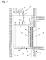
- the elevator system 10 includes an elevating member 12 elevating within a vertical shaft 16 constructed in a building 14 as it is guided by a plurality of vertical guide rails 18 extending on opposite side walls defining in part the shaft 16.
- a wire-winding device 22 with a driving motor 20 is secured at the top of the shaft 16.
- a wire 24 is wound at its one end around a drum of the wire-winding device 22 (not shown) and connected at its opposite end with the elevating member 12. This causes, by the driving of the motor 24 of the wire-winding device 22, the elevating member 12 to move up and down within the shaft 16.
- the elevating member 12 has an elevator cage 26 defining therein a room for the transportation of the passengers and cargoes and a frame 28 provided around the cage 26 for the structural reinforcement of the cage.
- a cage door system 38 is provided at a doorway (i.e., opening) of the cage 26 and a hall door system 40 is provided at each doorway (i.e., opening) of the hall 32.
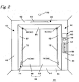
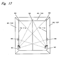
- the doorway 34 of the cage 26 is defined within a rectangular frame.
- the frame includes left and right vertical frame portions 42, lower horizontal frame portion 44 connecting between the lowermost ends of the vertical frame portions 42, and upper horizontal frame portion 46 connecting between the uppermost ends of the vertical frames 42.
- One of the vertical frame portions 42 has a front vertical wall 48 defining in part the room 30 and equipped with an operation panel 50.
- the operation panel 50 bears hall designation buttons 52, opening button 54, closing button 56, warning device 58 and display device 60.
- the upper horizontal frame 46 supports in its front wall a indication lamps 64 for the indication of the position of the cage 26 within the shaft 16.
- the door system 38 is a double-leaf door with two door portions or leaves 68, each protruding from leaf chambers 66 defined behind the left and right vertical frames 42 (see Figs. 4 and 5) into the doorway 34.
- Each door leaf 68 is drivingly connected with a drive mechanism 70 (see Fig. 1) provided at a certain position of the cage 26 so that it moves between a closing position (extracted position) and an opening position (retracted position). In the closing position, a leading vertical end surface of one door leaf contacts with the opposing leading vertical end surface of the other door leaf to close the doorway 34. In the opening position, on the other hand, each of the door leaves 68 is fully received within the associated leaf chamber 66.
- the drive mechanism 70 is one disclosed in the U.S Patent No. 3,783,977, which is equipped with an electric motor and a mechanism for changing a rotation generated by the motor into a translation of the door leaves and incorporated herein in its entirety by reference.
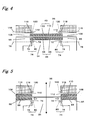
- the elevator cage 26 is provided with a safety installation 74 in order to prevent any member such as clothes from being drawn into the gap 72 defined between the vertical frame 42 and the opening door leaf 38.
- the safety installation 74 has a first optical device 78 and a second optical device 80 in a vertical plane crossing the doorway 34 (indicated by an imaginary line 76 in Fig. 4).
- the first optical device 78 is mounted in and flush with the opposing vertical surfaces 82 of the frame defining the left and right ends of the doorway 34.
- the second optical device 80 is mounted in and flush with the upper horizontal surface 84 of the frame defining the upper end of the doorway 34.
- a light emitter 88 is used for the first optical device 78 and a light receiver 90 is used for the second optical device 80 so that light emitted from the light emitter 88 is received by the light receiver 90.
- the first optical device 78 is provided adjacent to the lowermost end of the vertical surface 82 of the frame, preferably about 10-30cm away from the lowermost end of the vertical surface 82.
- the second optical device 80 is provided adjacent to the left/light ends of the upper horizontal surface 84 of the frame, preferably about 5-20cm away from the uppermost end of the vertical surface 82.
- the first and second optical devices 78 and 80 are mounted as close to the gap 72 as possible for the detection of any member adjacent to the gap 72.
- the first and second optical devices 78 and 80 are used to optically detect any member possibly existing adjacent to the gap 72. Therefore, so far as it could detect the member, the light emitted from the light emitter may be visible or invisible and is not limited to that having a specific wavelength.
- a surface of the light emitter 88 facing to the doorway 34 is substantially flush with the vertical surface 82 of the frame.
- the light receiver 90 is also substantially flush with the upper horizontal surface 46. This prevents the light emitter 88 and light receiver 90 from being damaged by the contacts with cargoes moving past the doorway 34.
- a surface of the light receiver 90 through which light is received is faced downward so that substantially no dust would adhere thereto.
- a surface of the light emitter 88 through which light is emitted is oriented vertically so that substantially no dust would adhere thereto.
- FIG. 3 another doorway or opening 36 of each hall of the building is defined within a rectangular frame.
- the frame includes left and right vertical frame portions (vertical walls) 92, lower horizontal frame portion (floor wall) 94 connecting between the lowermost ends of the vertical frame portions. 92, and upper horizontal frame portion 96 connecting between the uppermost ends of the vertical frames 92.
- left or/and right vertical wall portions of the doorway 36 support an upward hall button 98, downward hall button 100, warning device 102 and display device 104.
- the upper horizontal frame 96 supports an indicator or lamp 106 indicating the position of the cage 26 within the shaft 16.
- the hall door system 40 is also a double-leaf door with two door portions or leaves 110 each protruding from leaf chambers 108 defined behind the left and right vertical frames 92 (see Figs. 4 and 5) into the doorway 36.
- the left and right door leaves 110 are mechanically connected with a drive mechanism 111 (see Fig. 1) for opening/closing the hall door leaves.
- the drive mechanism 111 is so designed that, when the cage 26 arrives at the hall 32, it engages with the associated drive mechanism 70 mounted on the cage 26. This causes the hall door 40 to operate between the closed position shown in Fig. 3 and the opened position shown in Fig. 4, in synchronism with the opening and closing operation of the cage door 38.
- the hall 32 also has two sets of safety installation 114, similar to that for cage 26, provided on opposite sides of the doorway 36 to prevent any member such as clothes from being drawn into a gap 112 between the vertical frame 92 and the adjacent opening door leaf 110.
- the safety installation 114 includes a first optical device 118 and a second optical device 120 in a vertical plane (indicated by an imaginary line 116 in Fig. 3) crossing the doorway 36.
- the first optical device 118 is mounted in the vertical surfaces 122 of the frame defining the left and right ends of the doorway 36.
- the second optical device 120 is mounted in the upper horizontal surface 124 of the frame defining the upper end of the entrance 36.
- the first and second optical devices 118 and 120 have light emitter 88 and light receiver 90, respectively, so that light from the emitter 88 is received by the receiver 90.
- the first light optical device 118 is provided adjacent to the lowermost end of the vertical surface 122, preferably about 10-30cm away from the lowermost end of the vertical surface 122.
- the second optical device 120 is provided adjacent to the left/light ends of the upper horizontal surface 124, preferably about 5-20cm away from the uppermost end of the vertical surface 122. Also preferably, the first and second optical devices 118 and 120 are mounted as close to the gap 112 as possible, i.e., adjacent to the elevator shaft.
- the light emitting surface of the light emitter 88 is substantially flush with the vertical surface 122, and the light receiving surface of the light receiver 90 is substantially flush with the horizontal surface 124. This prevents not only the light emitters 88 and light receivers 90 from being damaged by the possible contacts with cargoes but also surfaces of the light emitters and receivers from being covered with dust.
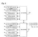
- Fig. 6 shows a control circuit 122 for the safety installations 74 and 114.
- the control circuit 122 includes a first control (central control) 124 for controlling various parts or devices mounted, in particular, in the building and a second control (cage control) 126 for controlling various parts and devices mounted on the cages 26.
- the first and second controls 124 and 126 are electrically communicated with each other.
- the first control 124 is connected with the light emitter 88, light receiver 90, warning device 102 and display device 104 provided for each hall 32 and an elevation control 128 for controlling the motor 20.
- the second control 126 is connected with the light emitter 88, light receiver 90, warning device 58 and display device 69 provided for each cage 26 and a door opening/closing control 130 for controlling the drive mechanism 70.
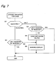
- Fig. 7 shows a flowchart showing the control operation of the second control 126 for the cage safety installation 74.
- the second control 126 determines whether the associated cage 26 is currently moving up or down within the elevator shaft 16. The determination is performed using a signal transmitted from the first control 124 to. the second control 126 for controlling the elevation of the cage 26. If the cage 26 is in the elevating operation, at step S2 the second control 126 determines whether an amount of light emitted from the light emitter 88 and then received by the light receiver 90 is less than a predetermined value (i.e., shaded condition).
- a predetermined value i.e., shaded condition
- the second control 126 energizes the associated cage warning device 58 to provide a necessary warning for the passengers in the cage 26.
- the warning may be a buzzer, message (e.g., "Please step away from door.”), or combination thereof.
- the warning message may be displayed simultaneously on the display device 60.
- the second control 126 determines at step S3 whether the amount of light received by the light receiver 90 is less than the predetermined value. If the determination is affirmative, meaning that any. member exists adjacent to the gap 72, at step S4 the second controller 126 transmits a certain signal to the opening/closing control 130 to prohibit the opening operation of the opposing doors 38 and 40. If the shading of the light receiver 90 is occurred during the opening operation of the doors 38 and 40, the opening operation comes to a halt. Then, at step S5 the warning device 58 of the cage 26 is energized to provide a necessary warning to the passengers in the cage 26.
- Fig. 8 is a flowchart showing a control operation of the first control 124 for the hall safety installation 114.
- the program flow is similar to that shown in Fig. 6.
- the first control 124 determines whether the cage 26 is elevating within the elevator shaft 16. If affirmative, another determination is made at step S7 whether the amount of light emitted from the light emitter 88 and then received by the light receiver 90 is less than the predetermined value (i.e., shaded condition). If also affirmative, i.e., it is detected that any member exists adjacent to the gap 112, at step S10 the first control 124 energizes the associated warning device 102 to provide a necessary warning to the passengers waiting at the hall 32. The content of the warning may be similar to that provided from the warning device 58 of the cage 26.
- the first control 124 determines at step S8 whether light from the hall light emitter 88 is detected by the hall light receiver 90. If the amount of light received by the hall light receiver 90 is less than the predetermined value, i.e., it is determined that any member exists adjacent to the gap 112, the first control 124 prohibits the opening operation of the doors 38 and 40 at step S9, and then energizes the warning device 102 at step S10, providing the necessary warning to the passengers waiting at the hall.
- the opening operation of the door 38 (40) is prohibited to prevent the member from being drawn into the gap 72 (112). Also, even if the cage 26 is in the elevating operation and also the member adjacent to the door 30 (40), if any, is detected, the warning is made to the passengers. This effectively prevents any member from being drawn into the gap 72 (112) at the opening of the door 38 (40).
- the above-described operation for making a halt of the opening operation of the door 38 and the associated door 40 is so effective in order to ensure the safe transportation of the passengers staying in the cage 26.
- the control may be designed so that where there is any passenger in the cage 26 the above-described opening operation is performed and where there is no passenger in the cage another operation is carried out.
- the elevator system 10 includes any means for detecting the existence of the passenger in the cage 26 or any live load such as passenger or passengers.
- the elevator system 10 includes a load detector 132 of the motor 20, another load detector 134 mounted at a connection between the wire 24 and the cage 26, or another load detector 136 mounted at the connection between the bottom of the cage 26 and the cage frame 28, which is electrically connected with the second control 126 as shown in Fig. 9.
- an image pick-up device 138 such as CCD camera may be provided. In this instance, an image picked up by the imaging device is processed to determine the existence of the passenger in the cage.
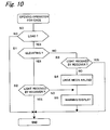
- Fig. 10 shows a control of the control circuit with the load detector.
- the second control 126 determines the existence of the live load (i.e., the existence of passenger) using the output from the load detector 132, 134 or 136. If no live load is detected, the second control 126 jumps steps S1-S5. On the other hand, if any live load is detected, the door opening operation described above with reference to Fig. 7 is performed.
- any failure or malfunction of the light emitter 88 and/or light receiver 90 does not cause an unnecessary halt of the opening operation of the doors.
- the opening operation of the doors with the load detector may be designed so that the light emitter 78 is energized at step S11 only if it is detected at step S0 that there is any passenger in the cage 26. Namely, the light emitter 78 is de-energized at step S11 if it is detected at step S0 that there is no passenger in the cage 26. In this instance, an unnecessary light emission is prevented, which extends a lifetime of the light emitter.
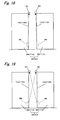
- one light emitter 88 is paired with one light receiver 90, as shown in Fig. 12 a plurality of light receivers 90 may be provided at different positions in the upper horizontal surface leaving different distances from the vertical surface 82, so that light from one light emitter 88 is detected by the plurality of light receivers 90. According to this embodiment, different operations may be made depending upon amounts of light received by the light receivers 90.
- the operation of the door mechanism 70 is prohibited at steps S21 and S22.
- the warning device 58, 102 and/or display device 60, 104 is energized at step S24 to make the necessary warning for the passenger or passengers.
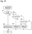
- the control may be designed so that amounts of light received by the two light receivers 90 (D1, D2) are compared with respective references at step S31. In this instance, if both amounts of light received by the receivers 90 are less than the predetermined values, it is determined that the light emitter 88 is in a malfunction state. Also, if either of the light amounts is less than the its predetermined value, it is determined that the corresponding light emitter 90 (D1 or D2) is in the malfunction state. Further, according to the determination, the warning devices 58 and 102 and display devices 60 and 104 are energized to make a warning.
- the operations described with reference to Fig. 14 may be made only when the load detected by the load detector 132, for example, is less than the predetermined, reference value which means that no passenger exists in the cage.
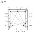
- the light receiver 90 may be provided at three portions, i.e., opposite end portions and mid-portion, of the upper horizontal surface 46 (124).
- the right and left light emitters 88 alternately emit a flux of light extending in a sector zone covering three light receivers for detecting any member in the doorway 34 (36) and adjacent to the gaps 72 (112).
- the light receiver 90 may be provided in the vertical surface 82 (122) so that light from the light emitter 88 provided on one vertical surface is received by the light receiver provided on the opposite vertical surface.
- the use of the plural light receivers 90 allows any member not only adjacent to the gaps 72 (112) but also adjacent to the doors 38 (40) to be detected effectively.
- the light receiver 90 mounted in the vertical surface 82, 122 causes the safety installation to detect any member in a lower position and thereby to prevent the same from being drawn into the gaps.
- the light from the left and right light emitters 88 is not required to be the sector beam. Also, another light emitter capable of changing a direction of light to be emitted can be used instead, which will be described below.
- the failure or malfunction of the light emitters 88 and light receivers 90 may be performed using the operation shown in Fig. 14. Also, according to this embodiment, a reduction of light emitted from the light emitters 88 can be detected by comparing amounts of light emitted from opposite light emitters 88 and then received by three light receivers 90 provided in the upper horizontal surface 46.
- the light emitter 88 is provided in the vertical surfaces 82 (122) and the light receiver 90 is provided above the light emitter 88, as shown in Figs. 16 and 17 it may be designed that the light receiver 90 is provided in the vertical surfaces 82 (122) and the light emitter 88 are provided in the upper horizontal surface 46 (124).
- the light emitter and receiver are positioned in a vertical plane extending across the opening defined between the fixed vertical frames, the light emitter and receiver may be provided in a vertical plane extending across an opening defined between the vertical leading end surface of the door leaf and another vertical surface opposing thereto.
- the another vertical surface may be the other door leaf of the double-leaf door, which cooperates with the leading end surface of one door leaf to open and close the doorway.
- the another vertical surface may be a fixed wall if the door is a single-leaf door.
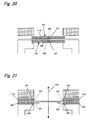
- the light emitter 88 is provided on the opposing, leading end vertical surfaces 140, 142 of the door leaves 68 and 110 of the double-leaf door.
- the light receivers 90 are fixed on the top portion 140 of the door and projected a certain distance from the vertical end toward the opposite door leaf, so that light from the light emitter 88 is detected by the light receivers 90 provided on the same door leaf 68 (110) (see Fig. 18) or provided on the opposite door leaf (see Fig. 19). Any member located between the opposing door leaves 68 (110) reduces an amount of light to be received by the light receiver, which causes the controller to detect the existence of the member.
- the light receivers 90 provided on the door leaves 68 (110) are offset in a direction perpendicular to the door movement (in Fig. 21, indicated by reference numeral 142) to prevent the mutual contact with each other at the closing of the door.
- the light emitter 88 is provided on the leading end surface 140 (142) of the door leaf and the light receiver 90 is provided thereabove, the light receiver 90 may be provided in the leading end surface 140 (142) and the light emitter 88 is provided thereabove.
- the present invention is equally applied for another elevator system in which the door 38 has a first door leaf or portion (low velocity door leaf) 150 and a second door leaf or portion (high velocity door leaf) 152.
- the second door leaf moves with the first door leaf and also relative to the first door leaf in the direction in which the first door leaf moves.
- one of the light emitter 88 and the light receiver 90 is provided at a certain position of the vertical surface 82 adjacent to its lowermost end and the other is provided at a certain position of the upper horizontal surface adjacent to the topmost end of the vertical surface 82.
- one of the light . emitter 88 and the light receiver 90 is provided in the leading, vertical end surface of the first door leaf 150 and adjacent to the lowermost end thereof and the other is provided at the top end of the same vertical end surface.
- the same structure may be provided to each hall door 60.
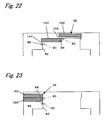
- Fig. 24 shows a specific structure of the light emitter 88 suitably mounted in the vertical surface 82 (122).
- the light emitter 88 has a transparent plate 162 mounted in an opening 160 defined in the vertical surface 82 (122).
- Light sources 166 are provided behind the transparent plate 162.
- Various commercially available light sources such as diode or semiconductor laser are used for the light source 166.
- Each light source 166 is inclined to the transparent plate 162 so that light emitted from the light source 166 is directed obliquely, i.e., upwardly in the drawing.
- the second major surface or incident surface 168 adjacent to the light sources 166 is stepped and inclined so that light emitted from each light source 166 enters the transparent plate 162 perpendicularly through the corresponding inclined surface portion of the transparent plate.
- each light source 166 is transmitted through the corresponding stepped surface portion 168 into the transparent plate 162 and then through the outer surface 164.
- the light outgoing from the transparent plate 162 refracts at the boundary surface and then travels toward the light receiver provided above the light emitter 88 in the vicinity of the vertical surface 82 (122).
- the positions of the outer surface 164 of the transparent plate 162 and the light sources 166 are determined so that an incident angle of light into the boundary of transparent plate 162 and air, i.e., outer surface of the transparent plate 162, is slightly less than the critical angle.
- another light receiver 172 is provided beside the light source 166 for detecting an amount of light to be emitted from the light source 166. In this instance, if the amount of detected light is less than the predetermined value, it is determined that the light source 166 is in the malfunction state.
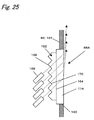
- Fig. 25 shows another embodiment of the light emitter.
- the light emitter 88A has a second transparent plate 174 mounted in an opening 160 defined in the vertical wall 82 (122).
- the stepped transparent plate 162 Provided behind the transparent plate 174 is the stepped transparent plate 162 described above, which is adhered to the second transparent plate 174 by a suitable material such as adhesive.
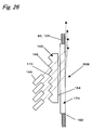
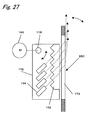
- the transparent plate 162. and the light sources 166 may be fixed separately or may be fixed on the same support member 176 as shown in the light emitter 88C in Fig. 27.
- the support member 176 is rotatably supported by a shaft 178 extending parallel to the access direction 142 (see Fig. 21) of the doorway.
- a DC motor 180 is connected to the shaft 178 to change a direction along which light is emitted from the transparent plate 174.
- the light sources 184 may be encapsulated in the transparent plate 182 mounted in the opening 160.
Landscapes
- Elevator Door Apparatuses (AREA)
- Power-Operated Mechanisms For Wings (AREA)
Abstract
Description
Claims (18)
- An elevator system having a pair of horizontally opposed vertical surfaces defining therebetween a doorway or opening to an elevator cage and a door moving horizontally to open and close the opening, comprising:wherein the first and second optical devices are positioned in a vertical plane crossing the opening and adjacent to the opening,a first optical device having a light emitter for emitting light and a second optical device having a light receiver for receiving the light emitted from the light emitter;
one of the first and second optical devices is positioned below the other of the first and second optical devices and mounted in the vertical surface. - The elevator system in accordance with claim 1, wherein the one optical device is mounted substantially flush with the vertical surface so that it does not protrude from the vertical surface.
- The elevator system in accordance with claim 1, wherein the other optical device is mounted adjacent to an uppermost end of the vertical surface in which the one optical device is mounted.
- The elevator system in accordance with claim 3, further comprising an upper horizontal surface connecting the uppermost ends of the vertical surfaces, wherein the other optical device is mounted in the upper horizontal surface.
- The elevator system in accordance with claim 1, further comprisinga drive mechanism for moving the door between a close position in which the door closes the opening and an open position in which the door opens the opening; anda controller for prohibiting a driving of the drive mechanism when an amount of light detected by the light receiver during a movement of the door from the close position toward the open position is less than a predetermined value.
- The elevator system in accordance with claim 5, wherein the second optical device has a second light receiver, each of the first and second light receivers being spaced a certain horizontal distance from the first optical device, the horizontal distance for the first light receiver being different from that for the second light receiver.
- The elevator system in accordance with claim 6, wherein the controller determines whether an amount of light received by each. of the first and second light receivers is less than the predetermined value and then takes a specific operation depending upon whether the amount of light received by the first light receiver is less than the predetermined value or the amount of light received by the second light receiver is less than the predetermined value.
- The elevator system in accordance with claim 6, wherein the first and second light receivers are arranged so that the horizontal distance between the first light receiver and the light emitter is less than that between the second light receiver and the light emitter, and the controller prohibits the driving of the drive mechanism when the amount of light received by the first light receiver is less than the predetermined value.
- The elevator system in accordance with claim 1, further comprisinga warning device;a drive mechanism for moving the door between a close position in which the door closes the opening and an open position in which the door opens the opening; anda controller for driving the warning device when an amount of light detected by the light receiver during a movement of the door from the close position toward the open position is less than a predetermined value.
- The elevator system in accordance with claim 1, wherein the vertical surface is defined in a fixed vertical frame adjacent to the door.
- The elevator system in accordance with claim 1, wherein the vertical surface is a vertical leading end surface of the door.
- The elevator system in accordance with claim 1, wherein the light emitter has a light source for emitting the light and a transparent plate through which the light is transmitted into the opening.
- The elevator system in accordance with claim 5, further comprisinga load detector for detecting a live load on the elevator cage; andmeans for driving the drive mechanism even when the amount of light detected by the light receiver during a movement of the door from the close position toward the open position is less than the predetermined value, provided that the live load detected by the load detector is less than a predetermined value.
- The elevator system in accordance with claim 9, further comprisinga load detector for detecting a live load on the elevator cage; andmeans for driving the warning device when the live load detected by the load detector is greater than a certain value and the amount of light detected by the light receiver during a movement of the door from the close position toward the open position is less than the predetermined value.
- The elevator system in accordance with claim 1, wherein the first optical device has a second light emitter, and
wherein, if both of amounts of light emitted from the first and second light emitters and then received by the light receiver are less than the predetermined value, the controller determines that the light receiver is in a malfunction state, and if the amount of light emitted from one of the first and second light emitters and then received by the light receiver is less than the predetermined value, the controller determines that the one light emitter is in a malfunction state. - The elevator system in accordance with claim 1, wherein the second optical device has a second light receiver, and
wherein, if both of amounts of light received by the first and second light receivers are less than the predetermined value, the controller determines that the light emitter is in a malfunction state, and if the amount of light received by one of the first and second light receivers is less than the predetermined value, the controller determines that the one light receiver is in a malfunction state. - The elevator. system in accordance with claim 1, wherein the opening is an opening defined in the elevator cage.
- The elevator system in accordance with claim 1, wherein the opening is an opening defined at a hall in a building.
Priority Applications (2)
| Application Number | Priority Date | Filing Date | Title |
|---|---|---|---|
| EP06026096.5A EP1762531B2 (en) | 2001-03-12 | 2002-03-05 | Safety system for elevator doors |
| DE60220205.1T DE60220205T3 (en) | 2001-03-12 | 2002-03-05 | Security system for elevator doors |
Applications Claiming Priority (2)
| Application Number | Priority Date | Filing Date | Title |
|---|---|---|---|
| JP2001068445A JP3958940B2 (en) | 2001-03-12 | 2001-03-12 | Door device and elevator device |
| JP2001068445 | 2001-03-12 |
Related Child Applications (2)
| Application Number | Title | Priority Date | Filing Date |
|---|---|---|---|
| EP06026096.5A Division EP1762531B2 (en) | 2001-03-12 | 2002-03-05 | Safety system for elevator doors |
| EP06026096.5A Division-Into EP1762531B2 (en) | 2001-03-12 | 2002-03-05 | Safety system for elevator doors |
Publications (4)
| Publication Number | Publication Date |
|---|---|
| EP1243544A2 true EP1243544A2 (en) | 2002-09-25 |
| EP1243544A3 EP1243544A3 (en) | 2004-05-19 |
| EP1243544B1 EP1243544B1 (en) | 2007-05-23 |
| EP1243544B2 EP1243544B2 (en) | 2020-11-18 |
Family
ID=18926635
Family Applications (2)
| Application Number | Title | Priority Date | Filing Date |
|---|---|---|---|
| EP02004375.8A Expired - Lifetime EP1243544B2 (en) | 2001-03-12 | 2002-03-05 | Safety system for elevator doors |
| EP06026096.5A Expired - Lifetime EP1762531B2 (en) | 2001-03-12 | 2002-03-05 | Safety system for elevator doors |
Family Applications After (1)
| Application Number | Title | Priority Date | Filing Date |
|---|---|---|---|
| EP06026096.5A Expired - Lifetime EP1762531B2 (en) | 2001-03-12 | 2002-03-05 | Safety system for elevator doors |
Country Status (6)
| Country | Link |
|---|---|
| US (1) | US6631788B2 (en) |
| EP (2) | EP1243544B2 (en) |
| JP (1) | JP3958940B2 (en) |
| KR (1) | KR100449794B1 (en) |
| CN (1) | CN1276867C (en) |
| DE (2) | DE60220205T3 (en) |
Cited By (5)
| Publication number | Priority date | Publication date | Assignee | Title |
|---|---|---|---|---|
| WO2004002869A1 (en) | 2002-06-28 | 2004-01-08 | Mitsubishi Denki Kabushiki Kaisha | Door control device of elevator |
| EP2141111A4 (en) * | 2007-04-24 | 2014-01-01 | Mitsubishi Electric Corp | SLIDING DOOR DEVICE |
| EP2298686A4 (en) * | 2008-07-16 | 2014-01-29 | Mitsubishi Electric Corp | SLIDING DOOR DEVICE AND ELEVATOR |
| EP3091163A3 (en) * | 2015-05-04 | 2017-03-15 | Franz Xaver Meiller Fahrzeug- und Maschinenfabrik-GmbH & Co KG | Sliding door, in particular elevator sliding door |
| EP3196160A1 (en) * | 2016-01-19 | 2017-07-26 | Inventio AG | Method for controlling a closing operation of an elevator door of an elevator cabin |
Families Citing this family (30)
| Publication number | Priority date | Publication date | Assignee | Title |
|---|---|---|---|---|
| WO2001096226A1 (en) * | 2000-06-13 | 2001-12-20 | Cedes Ag | Safety device for elevator doors |
| JP3958940B2 (en) * | 2001-03-12 | 2007-08-15 | 三菱電機株式会社 | Door device and elevator device |
| JP3995522B2 (en) * | 2002-05-08 | 2007-10-24 | 三菱電機株式会社 | Elevator equipment |
| JP4601935B2 (en) * | 2003-10-14 | 2010-12-22 | 三菱電機株式会社 | Elevator door safety device |
| JP4481091B2 (en) * | 2004-06-15 | 2010-06-16 | 三菱電機株式会社 | Sliding door device |
| ES2376759T3 (en) * | 2004-09-03 | 2012-03-16 | Otis Elevator Company | Elevator equipped with a device for the detection of foreign objects, and in particular fingers, between the doors and the adjacent walls of an elevator car with glass doors |
| JP2006143443A (en) * | 2004-11-24 | 2006-06-08 | Otis Elevator Co | Safety device of door |
| FR2883584B1 (en) * | 2005-03-25 | 2007-06-08 | Maviflex Sa Sa | DEVICE FOR DETECTING AN OBSTACLE AND FOR LIMITING THE EFFORT OF AN APRON OF A HANDLING DOOR |
| JP4525473B2 (en) * | 2005-06-06 | 2010-08-18 | トヨタ自動車株式会社 | Mobile robot position control system and position control method |
| JP2007137555A (en) * | 2005-11-16 | 2007-06-07 | Otis Elevator Co | Elevator door safety device |
| EP2062842A1 (en) * | 2007-11-23 | 2009-05-27 | Inventio Ag | Monitoring device for a lift, lift and method for monitoring a lift |
| JP5287597B2 (en) * | 2009-08-18 | 2013-09-11 | 三菱電機株式会社 | Elevator sliding door device |
| US8471704B2 (en) * | 2010-04-13 | 2013-06-25 | Cedes Ag | Door system comprising a sensor device for monitoring vertical door edges |
| CN102235732B (en) * | 2010-04-26 | 2013-08-28 | 宁波奥克斯空调有限公司 | Device and method for controlling sliding door of air conditioner |
| KR101305719B1 (en) * | 2013-03-22 | 2013-09-09 | 이호연 | Safety device of elevator door for hand protection |
| JP6209905B2 (en) * | 2013-09-04 | 2017-10-11 | 富士電機株式会社 | Door control device |
| KR101442577B1 (en) | 2013-12-05 | 2014-10-07 | 이호연 | Safety device of elevator for hand protection using tilting function |
| GB2526072B (en) * | 2014-05-02 | 2019-08-14 | Ensota Ltd | A method of operating an automatic door installation |
| ES2768749T3 (en) * | 2015-03-19 | 2020-06-23 | Wittur Holding Gmbh | Elevator door having two sliding door panels |
| GB201506645D0 (en) * | 2015-04-20 | 2015-06-03 | Vip Lift & Escalator Services Ltd | An elevator system and a method of adapting an elevator system |
| CA3105934C (en) * | 2016-01-11 | 2022-08-02 | Opex Corporation | Material handling apparatus with delivery vehicles |
| GB2549760B (en) * | 2016-04-28 | 2018-04-25 | Ensota Guangzhou Tech Ltd | An automatic door installation |
| KR101793404B1 (en) * | 2017-04-24 | 2017-11-03 | 윤일식 | Safety device of elevator for hand protection |
| KR101870580B1 (en) * | 2017-08-30 | 2018-06-22 | 윤일식 | Safety device of elevator for hand protection |
| CN110526058B (en) * | 2018-05-23 | 2022-06-03 | 奥的斯电梯公司 | Elevator door monitoring system, elevator system and elevator door monitoring method |
| CN108715384B (en) * | 2018-06-25 | 2024-05-10 | 苏州德林宝电梯制造有限公司 | Elevator landing door anti-collision safety early warning system |
| JP6716741B1 (en) * | 2019-03-20 | 2020-07-01 | 東芝エレベータ株式会社 | Elevator user detection system |
| JP6799802B1 (en) * | 2020-04-20 | 2020-12-16 | フジテック株式会社 | Elevator safety device |
| CN111824911A (en) * | 2020-07-20 | 2020-10-27 | 吴建国 | Elevator landing door safety protection method |
| CN121568889A (en) | 2023-07-26 | 2026-02-24 | 因温特奥股份公司 | Sensor unit |
Family Cites Families (19)
| Publication number | Priority date | Publication date | Assignee | Title |
|---|---|---|---|---|
| CH523199A (en) | 1970-12-30 | 1972-05-31 | Inventio Ag | Door drive device with locking mechanism for elevators |
| JPS5349868A (en) † | 1976-10-18 | 1978-05-06 | Daisaku Hayashi | Apparatus for incinerating wasted tire and such |
| USRE33668E (en) * | 1981-02-10 | 1991-08-20 | Otis Elevator Company | Detection device having energy transmitters located at vertically spaced apart points along movable doors |
| US4621452A (en) * | 1985-01-18 | 1986-11-11 | Deeg Wyman L | Powered sliding door safety system |
| JPH07106867B2 (en) † | 1986-09-04 | 1995-11-15 | 株式会社東芝 | Doorway safety device for elevator |
| GB2254916B (en) * | 1991-04-15 | 1993-12-22 | John Trett | Detection systems |
| GB9120267D0 (en) * | 1991-09-23 | 1991-11-06 | Memco Med Ltd | Lift door apparatus |
| JP2609020B2 (en) | 1991-10-16 | 1997-05-14 | 三菱電機株式会社 | Elevator door control device |
| GB9415772D0 (en) * | 1994-08-04 | 1994-09-28 | Memco Ltd | Lift installation |
| JPH08259158A (en) * | 1995-03-17 | 1996-10-08 | Mitsubishi Electric Corp | Safety device for opening and closing elevator doors |
| JPH0971377A (en) * | 1995-09-06 | 1997-03-18 | Mitsubishi Electric Corp | Elevator doorway safety device |
| JPH10152277A (en) * | 1996-11-21 | 1998-06-09 | Mitsubishi Electric Corp | Elevator door opening and closing device |
| JPH10265157A (en) * | 1997-03-19 | 1998-10-06 | Mitsubishi Electric Corp | Elevator doorway safety devices |
| US5886307A (en) * | 1997-06-23 | 1999-03-23 | Otis Elevator Company | Safety detection system for sliding doors |
| JPH11278776A (en) * | 1998-03-30 | 1999-10-12 | Hitachi Building Systems Co Ltd | Elevator control device |
| JP3769119B2 (en) † | 1998-04-04 | 2006-04-19 | 株式会社 堀場アドバンスドテクノ | Volume resistivity meter, liquid purity monitoring apparatus including the same, liquid resistivity measuring method, and liquid purity monitoring method using the same |
| JPH11310375A (en) * | 1998-04-27 | 1999-11-09 | Hitachi Building Systems Co Ltd | Elevator door safety device |
| US6167991B1 (en) * | 2000-02-28 | 2001-01-02 | Otis Elevator Company | Method and apparatus for detecting position of an elevator door |
| JP3958940B2 (en) * | 2001-03-12 | 2007-08-15 | 三菱電機株式会社 | Door device and elevator device |
-
2001
- 2001-03-12 JP JP2001068445A patent/JP3958940B2/en not_active Expired - Lifetime
-
2002
- 2002-03-05 DE DE60220205.1T patent/DE60220205T3/en not_active Expired - Lifetime
- 2002-03-05 DE DE60236694T patent/DE60236694D1/en not_active Expired - Lifetime
- 2002-03-05 EP EP02004375.8A patent/EP1243544B2/en not_active Expired - Lifetime
- 2002-03-05 EP EP06026096.5A patent/EP1762531B2/en not_active Expired - Lifetime
- 2002-03-11 KR KR10-2002-0012826A patent/KR100449794B1/en not_active Expired - Lifetime
- 2002-03-12 US US10/094,993 patent/US6631788B2/en not_active Expired - Lifetime
- 2002-03-12 CN CNB02107061XA patent/CN1276867C/en not_active Expired - Lifetime
Cited By (7)
| Publication number | Priority date | Publication date | Assignee | Title |
|---|---|---|---|---|
| WO2004002869A1 (en) | 2002-06-28 | 2004-01-08 | Mitsubishi Denki Kabushiki Kaisha | Door control device of elevator |
| EP1518814A4 (en) * | 2002-06-28 | 2008-11-19 | Mitsubishi Electric Corp | DEVICE FOR CONTROLLING THE DOOR OF AN ELEVATOR |
| EP2141111A4 (en) * | 2007-04-24 | 2014-01-01 | Mitsubishi Electric Corp | SLIDING DOOR DEVICE |
| EP2298686A4 (en) * | 2008-07-16 | 2014-01-29 | Mitsubishi Electric Corp | SLIDING DOOR DEVICE AND ELEVATOR |
| EP3091163A3 (en) * | 2015-05-04 | 2017-03-15 | Franz Xaver Meiller Fahrzeug- und Maschinenfabrik-GmbH & Co KG | Sliding door, in particular elevator sliding door |
| EP3293333A1 (en) * | 2015-05-04 | 2018-03-14 | Franz Xaver Meiller Fahrzeug- und Maschinenfabrik-GmbH & Co KG | Sliding door, in particular elevator sliding door |
| EP3196160A1 (en) * | 2016-01-19 | 2017-07-26 | Inventio AG | Method for controlling a closing operation of an elevator door of an elevator cabin |
Also Published As
| Publication number | Publication date |
|---|---|
| DE60236694D1 (en) | 2010-07-22 |
| DE60220205D1 (en) | 2007-07-05 |
| KR100449794B1 (en) | 2004-09-22 |
| JP2002265175A (en) | 2002-09-18 |
| US20020125077A1 (en) | 2002-09-12 |
| EP1762531A2 (en) | 2007-03-14 |
| EP1243544B2 (en) | 2020-11-18 |
| EP1762531A3 (en) | 2008-07-30 |
| DE60220205T3 (en) | 2021-04-01 |
| EP1243544B1 (en) | 2007-05-23 |
| DE60220205T2 (en) | 2008-01-17 |
| JP3958940B2 (en) | 2007-08-15 |
| US6631788B2 (en) | 2003-10-14 |
| EP1762531B2 (en) | 2019-12-04 |
| CN1276867C (en) | 2006-09-27 |
| CN1375444A (en) | 2002-10-23 |
| EP1762531B1 (en) | 2010-06-09 |
| EP1762531B8 (en) | 2019-10-23 |
| EP1243544A3 (en) | 2004-05-19 |
| KR20020072784A (en) | 2002-09-18 |
Similar Documents
| Publication | Publication Date | Title |
|---|---|---|
| EP1243544B1 (en) | Safety system for elevator doors | |
| US6962239B2 (en) | Sliding door system with optical detector for safe door opening and closing | |
| CN101426711B (en) | Sliding door apparatus and elevator | |
| JP2002265175A5 (en) | ||
| CN1251957C (en) | Safety device for elevator doors | |
| JP2008115016A (en) | Assembly of safety detection system for sliding door | |
| JP2009051615A (en) | Elevator device | |
| EP2316777A1 (en) | Elevator door device | |
| JP2001316052A (en) | Elevator position detector | |
| JP5287997B2 (en) | Elevator door control device | |
| EP2080725B1 (en) | Elevator system | |
| JP5474067B2 (en) | Sliding door device and elevator | |
| WO2006057898A2 (en) | Door safety device | |
| JP3372887B2 (en) | Elevator doorway safety devices | |
| KR101324093B1 (en) | Protection apparatus and method for control of elevator entrance | |
| JP5577636B2 (en) | Entrance / exit device and elevator device | |
| EP1795486A1 (en) | Interlock device for elevator | |
| CN114206765B (en) | Devices for unlocking elevator doors in vertical and horizontal elevator installations | |
| JP3156432B2 (en) | Elevator door safety device | |
| JP2006160481A (en) | Door sensor device for elevator | |
| WO2024218821A1 (en) | Abnormality detection system | |
| JPWO2007142074A1 (en) | Sliding door device and elevator | |
| JP2000053349A (en) | Elevator door closing control device | |
| JP2000118926A (en) | Elevator doorway safety devices |
Legal Events
| Date | Code | Title | Description |
|---|---|---|---|
| PUAI | Public reference made under article 153(3) epc to a published international application that has entered the european phase |
Free format text: ORIGINAL CODE: 0009012 |
|
| 17P | Request for examination filed |
Effective date: 20020305 |
|
| AK | Designated contracting states |
Kind code of ref document: A2 Designated state(s): AT BE CH CY DE DK ES FI FR GB GR IE IT LI LU MC NL PT SE TR |
|
| AX | Request for extension of the european patent |
Free format text: AL;LT;LV;MK;RO;SI |
|
| PUAL | Search report despatched |
Free format text: ORIGINAL CODE: 0009013 |
|
| AK | Designated contracting states |
Kind code of ref document: A3 Designated state(s): AT BE CH CY DE DK ES FI FR GB GR IE IT LI LU MC NL PT SE TR |
|
| AX | Request for extension of the european patent |
Extension state: AL LT LV MK RO SI |
|
| AKX | Designation fees paid |
Designated state(s): DE FR NL |
|
| RAP1 | Party data changed (applicant data changed or rights of an application transferred) |
Owner name: MITSUBISHI DENKI KABUSHIKI KAISHA |
|
| GRAP | Despatch of communication of intention to grant a patent |
Free format text: ORIGINAL CODE: EPIDOSNIGR1 |
|
| GRAS | Grant fee paid |
Free format text: ORIGINAL CODE: EPIDOSNIGR3 |
|
| RIN1 | Information on inventor provided before grant (corrected) |
Inventor name: TAKASHIMA, KAZUO,MITSUBISHI DENKI K.K. Inventor name: KOURA, KUNIKAZU,MITSUBISHI DENKI K.K. Inventor name: NANNO, KOICHI,MITSUBISHI DENKI K.K. Inventor name: NAKAJIMA, HAJIME,MITSUBISHI DENKI K.K. Inventor name: SHIKAI, MASAHIRO,MITSUBISHI DENKI K.K. Inventor name: TAKAHASHI, TATSUSHI,MITSUBISHI DENKI K.K. Inventor name: FUJIKI, TAKESHI,MITSUBISHI DENKI K.K. Inventor name: ABE, SHIGERU,MITSUBISHI DENKI K.K. Inventor name: NAKASHIMA, TOSHIRO,MITSUBISHI DENKI K.K. Inventor name: YAMAKAWA, SHIGEKI,MITSUBISHI DENKI K.K. |
|
| GRAA | (expected) grant |
Free format text: ORIGINAL CODE: 0009210 |
|
| AK | Designated contracting states |
Kind code of ref document: B1 Designated state(s): DE FR NL |
|
| REF | Corresponds to: |
Ref document number: 60220205 Country of ref document: DE Date of ref document: 20070705 Kind code of ref document: P |
|
| ET | Fr: translation filed | ||
| PLBI | Opposition filed |
Free format text: ORIGINAL CODE: 0009260 |
|
| 26 | Opposition filed |
Opponent name: OTIS ELEVATOR COMPANY Effective date: 20080219 |
|
| PLAX | Notice of opposition and request to file observation + time limit sent |
Free format text: ORIGINAL CODE: EPIDOSNOBS2 |
|
| NLR1 | Nl: opposition has been filed with the epo |
Opponent name: OTIS ELEVATOR COMPANY |
|
| PLBB | Reply of patent proprietor to notice(s) of opposition received |
Free format text: ORIGINAL CODE: EPIDOSNOBS3 |
|
| RDAF | Communication despatched that patent is revoked |
Free format text: ORIGINAL CODE: EPIDOSNREV1 |
|
| APBM | Appeal reference recorded |
Free format text: ORIGINAL CODE: EPIDOSNREFNO |
|
| APBP | Date of receipt of notice of appeal recorded |
Free format text: ORIGINAL CODE: EPIDOSNNOA2O |
|
| APAH | Appeal reference modified |
Free format text: ORIGINAL CODE: EPIDOSCREFNO |
|
| APBQ | Date of receipt of statement of grounds of appeal recorded |
Free format text: ORIGINAL CODE: EPIDOSNNOA3O |
|
| APBU | Appeal procedure closed |
Free format text: ORIGINAL CODE: EPIDOSNNOA9O |
|
| REG | Reference to a national code |
Ref country code: FR Ref legal event code: PLFP Year of fee payment: 15 |
|
| REG | Reference to a national code |
Ref country code: FR Ref legal event code: PLFP Year of fee payment: 16 |
|
| REG | Reference to a national code |
Ref country code: FR Ref legal event code: PLFP Year of fee payment: 17 |
|
| PLAB | Opposition data, opponent's data or that of the opponent's representative modified |
Free format text: ORIGINAL CODE: 0009299OPPO |
|
| R26 | Opposition filed (corrected) |
Opponent name: OTIS ELEVATOR COMPANY Effective date: 20080219 |
|
| PUAH | Patent maintained in amended form |
Free format text: ORIGINAL CODE: 0009272 |
|
| STAA | Information on the status of an ep patent application or granted ep patent |
Free format text: STATUS: PATENT MAINTAINED AS AMENDED |
|
| 27A | Patent maintained in amended form |
Effective date: 20201118 |
|
| AK | Designated contracting states |
Kind code of ref document: B2 Designated state(s): DE FR NL |
|
| REG | Reference to a national code |
Ref country code: DE Ref legal event code: R102 Ref document number: 60220205 Country of ref document: DE |
|
| REG | Reference to a national code |
Ref country code: NL Ref legal event code: MP Effective date: 20070523 |
|
| PGFP | Annual fee paid to national office [announced via postgrant information from national office to epo] |
Ref country code: FR Payment date: 20210210 Year of fee payment: 20 Ref country code: NL Payment date: 20210212 Year of fee payment: 20 |
|
| PGFP | Annual fee paid to national office [announced via postgrant information from national office to epo] |
Ref country code: DE Payment date: 20210224 Year of fee payment: 20 |
|
| PG25 | Lapsed in a contracting state [announced via postgrant information from national office to epo] |
Ref country code: NL Free format text: LAPSE BECAUSE OF FAILURE TO SUBMIT A TRANSLATION OF THE DESCRIPTION OR TO PAY THE FEE WITHIN THE PRESCRIBED TIME-LIMIT Effective date: 20070523 |
|
| REG | Reference to a national code |
Ref country code: DE Ref legal event code: R071 Ref document number: 60220205 Country of ref document: DE |