EP1243126B1 - Methods and Apparatus for detecting unauthorized copies of digital objects on the basis of fingerprinting - Google Patents
Methods and Apparatus for detecting unauthorized copies of digital objects on the basis of fingerprinting Download PDFInfo
- Publication number
- EP1243126B1 EP1243126B1 EP00974015A EP00974015A EP1243126B1 EP 1243126 B1 EP1243126 B1 EP 1243126B1 EP 00974015 A EP00974015 A EP 00974015A EP 00974015 A EP00974015 A EP 00974015A EP 1243126 B1 EP1243126 B1 EP 1243126B1
- Authority
- EP
- European Patent Office
- Prior art keywords
- fingerprinting
- word
- blocks
- gamma
- block
- Prior art date
- Legal status (The legal status is an assumption and is not a legal conclusion. Google has not performed a legal analysis and makes no representation as to the accuracy of the status listed.)
- Expired - Lifetime
Links
Images


Classifications
-
- G—PHYSICS
- G06—COMPUTING OR CALCULATING; COUNTING
- G06T—IMAGE DATA PROCESSING OR GENERATION, IN GENERAL
- G06T1/00—General purpose image data processing
- G06T1/0021—Image watermarking
- G06T1/005—Robust watermarking, e.g. average attack or collusion attack resistant
-
- H—ELECTRICITY
- H04—ELECTRIC COMMUNICATION TECHNIQUE
- H04N—PICTORIAL COMMUNICATION, e.g. TELEVISION
- H04N1/00—Scanning, transmission or reproduction of documents or the like, e.g. facsimile transmission; Details thereof
- H04N1/32—Circuits or arrangements for control or supervision between transmitter and receiver or between image input and image output device, e.g. between a still-image camera and its memory or between a still-image camera and a printer device
- H04N1/32101—Display, printing, storage or transmission of additional information, e.g. ID code, date and time or title
-
- G—PHYSICS
- G06—COMPUTING OR CALCULATING; COUNTING
- G06T—IMAGE DATA PROCESSING OR GENERATION, IN GENERAL
- G06T2201/00—General purpose image data processing
- G06T2201/005—Image watermarking
- G06T2201/0051—Embedding of the watermark in the spatial domain
-
- G—PHYSICS
- G06—COMPUTING OR CALCULATING; COUNTING
- G06T—IMAGE DATA PROCESSING OR GENERATION, IN GENERAL
- G06T2201/00—General purpose image data processing
- G06T2201/005—Image watermarking
- G06T2201/0061—Embedding of the watermark in each block of the image, e.g. segmented watermarking
-
- G—PHYSICS
- G06—COMPUTING OR CALCULATING; COUNTING
- G06T—IMAGE DATA PROCESSING OR GENERATION, IN GENERAL
- G06T2201/00—General purpose image data processing
- G06T2201/005—Image watermarking
- G06T2201/0063—Image watermarking in relation to collusion attacks, e.g. collusion attack resistant
-
- H—ELECTRICITY
- H04—ELECTRIC COMMUNICATION TECHNIQUE
- H04N—PICTORIAL COMMUNICATION, e.g. TELEVISION
- H04N2201/00—Indexing scheme relating to scanning, transmission or reproduction of documents or the like, and to details thereof
- H04N2201/32—Circuits or arrangements for control or supervision between transmitter and receiver or between image input and image output device, e.g. between a still-image camera and its memory or between a still-image camera and a printer device
- H04N2201/3201—Display, printing, storage or transmission of additional information, e.g. ID code, date and time or title
- H04N2201/3225—Display, printing, storage or transmission of additional information, e.g. ID code, date and time or title of data relating to an image, a page or a document
- H04N2201/3233—Display, printing, storage or transmission of additional information, e.g. ID code, date and time or title of data relating to an image, a page or a document of authentication information, e.g. digital signature, watermark
- H04N2201/3235—Checking or certification of the authentication information, e.g. by comparison with data stored independently
-
- H—ELECTRICITY
- H04—ELECTRIC COMMUNICATION TECHNIQUE
- H04N—PICTORIAL COMMUNICATION, e.g. TELEVISION
- H04N2201/00—Indexing scheme relating to scanning, transmission or reproduction of documents or the like, and to details thereof
- H04N2201/32—Circuits or arrangements for control or supervision between transmitter and receiver or between image input and image output device, e.g. between a still-image camera and its memory or between a still-image camera and a printer device
- H04N2201/3201—Display, printing, storage or transmission of additional information, e.g. ID code, date and time or title
- H04N2201/3225—Display, printing, storage or transmission of additional information, e.g. ID code, date and time or title of data relating to an image, a page or a document
- H04N2201/3233—Display, printing, storage or transmission of additional information, e.g. ID code, date and time or title of data relating to an image, a page or a document of authentication information, e.g. digital signature, watermark
- H04N2201/3236—Details of authentication information generation
Definitions
- This invention pertains to methods and systems for fingerprinting digital data.
- Fingerprinting is a technique that involves uniquely marking each copy of a particular object, and associating each uniquely marked copy with a particular entity to which the copy is distributed. If unauthorized copies of the uniquely marked copy are made, the fingerprint can be traced back to the original entity to which the copy was initially distributed.
- a map maker When a map maker produces a map, they may want to ensure that those individuals to whom the map is distributed do not make unauthorized copies of the map and distribute them to others.
- One way that the map maker might protect his maps is to introduce a different trivial error, or fingerprint, (e.g. a non-existent street) into each of the copies of the map that are distributed.
- fingerprint e.g. a non-existent street
- Each fingerprint is then associated with an individual to whom the map is to be distributed.
- By associating each different fingerprint with a different individual if and when unauthorized copies of that individual's copy are uncovered, they can be traced back to the original individual by virtue of the unique fingerprint that the map contains.
- One problem with this type of fingerprinting can arise when two or more individuals collude for the purpose of discovering their fingerprints. That is, when two or more individuals get together and compare their maps, they can, given enough time, ascertain their unique fingerprints by simply looking for the differences between their maps. If they can ascertain their fingerprint, they can alter it and therefore possibly avoid detection.
- fingerprinting digital data e.g. software, documents, music, and video
- fingerprinting digital data for purposes of detecting or deterring unauthorized copying has become particularly important.
- collusion by different individuals in the digital context can pose challenges to the owners and distributors of such digital data.
- further strides are necessary to increase the breadth of protection that is afforded by digital fingerprinting.
- some protection against collusion is provided, but only when the number of colluders is relatively small.
- this invention arose out of concerns associated with providing improved methods and systems for fingerprinting digital data.
- a watermark is constructed as an independent and identically distributed random vector that is imperceptibly inserted in a spread-spectrum-like fashion into the perceptually most significant spectral components.
- the original image can be successfully registered against the transformed watermarked image to unambiguously identify the owner.
- An identification code is permanently embedded in the data. Data does not include ASCII representations of text.
- a watermark may contain the identity of the purchaser of a particular copy. The watermark should be robust to combining copies of the same data set to destroy the watermarks.
- a frequency-based method is described for watermarking in the frequency domain by spread spectrum coding a watermark.
- the watermark is spread throughout the spectrum of an image.
- a watermark consists of a sequence of real numbers, and continuous valued watermarks are used. Binary watermarks are rejected because they are less robust to attacks based on collusion of several independently watermarked copies of an Image.
- US 5, 930, 369 A similar prior art is described in US 5, 930, 369 .
- WO 97/34391 A1 discloses a watermarking process resilient to collusion attacks. Watermarks are used to prevent unlawful copying of audio, video and other media that can be digitised. Collusion-type attacks are prevented by constructing a watermark using randomness in a specific way.
- EP 0 951 183 A2 describes an electronic watermark processing apparatus.
- DSSS Direct Sequence Spread Spectrum
- Unique fingerprinting words are defined where each includes at least one spread sequence.
- a fingerprinting word comprises a plurality of symbols, called " ⁇ symbols.” Each ⁇ symbol is composed of 2c-1 blocks, where c represents the number of colluders that are desired to be protected against. Each block contains d spread sequence chips.
- the fingerprinting words are assigned to a plurality of entities to which protected objects embedded with the fingerprinting words are to be distributed.
- each block is computed in accordance with a defined function and blocks whose weights satisfy a predetermined relationship are "clipped" to a so-called working range.
- Each ⁇ -symbol of the altered fingerprinting word is then processed to produce a set of one or more "colors" that might be the subject of a collusion.
- Each ⁇ -symbol in the fingerprinting word for each entity is then evaluated against a corresponding produced set and the entity having the most overall incriminating "colors" is incriminated.
- each fingerprinting word is associated with one of a number of entities or users to which the fingerprinted objects are to be distributed.
- each fingerprinting word contains a plurality of ⁇ -symbols, and each ⁇ -symbol contains a plurality of blocks.
- Each block comprises a spread sequence that has a plurality of spread sequence chips.
- an altered object When an altered object is received, it is first processed to identify the embedded spread sequence chips. Once the chips are identified, a relative weight function is defined and used to calculate the relative weight for each block. The relative weight calculations for each block are analyzed in accordance with a predetermined relationship which determines which of the blocks gets "clipped" to a predefined working range.
- the clipped blocks are those that are likely to be “unseen” in the sense that the colluders who colluded to produce the altered object likely were not able to see these blocks, i.e. they were the same.
- the blocks that are not clipped constitute those blocks that likely were “seen” and therefore possibly altered by the colluders.
- each ⁇ -symbol of the altered object is processed to produce a set of possible ⁇ -symbols that might be the subject of a collusion.
- the collection of sets defines a matrix.
- Each ⁇ symbol for a user's unique fingerprint is then compared with the set for each corresponding ⁇ -symbol in the matrix and a count is kept of the number of times each user's ⁇ symbol coincides with a ⁇ -symbol that is found in a particular set.
- the user with the highest count is selected as a colluder that produced the altered object.
- Fig. 1 shows a general example of a computer 130 that can be used in accordance with the invention.
- Various numbers of computers such as that shown can be used in the context of a distributed computing environment.
- Computer 130 includes one or more processors or processing units 132, a system memory 134, and a bus 136 that couples various system components including the system memory 134 to processors 132.
- the bus 136 represents one or more of any of several types of bus structures, including a memory bus or memory controller, a peripheral bus, an accelerated graphics port, and a processor or local bus using any of a variety of bus architectures.
- the system memory 134 includes read only memory (ROM) 138 and random access memory (RAM) 140.
- ROM read only memory
- RAM random access memory
- a basic input/output system (BIOS) 142 containing the basic routines that help to transfer information between elements within computer 130, such as during start-up, is stored in ROM 138.
- Computer 130 further includes a hard disk drive 144 for reading from and writing to a hard disk (not shown), a magnetic disk drive 146 for reading from and writing to a removable magnetic disk 148, and an optical disk drive 150 for reading from or writing to a removable optical disk 152 such as a CD ROM or other optical media.
- the hard disk drive 144, magnetic disk drive 146, and optical disk drive 150 are connected to the bus 136 by an SCSI interface 154 or some other appropriate interface.
- the drives and their associated computer-readable media provide nonvolatile storage of computer-readable instructions, data structures, program modules and other data for computer 130.
- a number of program modules may be stored on the hard disk 144, magnetic disk 148, optical disk 152, ROM 138, or RAM 140, including an operating system 158, one or more application programs 160, other program modules 162, and program data 164.
- a user may enter commands and information into computer 130 through input devices such as a keyboard 166 and a pointing device 168.
- Other input devices may include a microphone, joystick, game pad, satellite dish, scanner, or the like.
- These and other input devices are connected to the processing unit 132 through an interface 170 that is coupled to the bus 136.
- a monitor 172 or other type of display device is also connected to the bus 136 via an interface, such as a video adapter 174.
- personal computers typically include other peripheral output devices (not shown) such as speakers and printers.
- Computer 130 commonly operates in a networked environment using logical connections to one or more remote computers, such as a remote computer 176.
- the remote computer 176 may be another personal computer, a server, a router, a network PC, a peer device or other common network node, and typically includes many or all of the elements described above relative to computer 130, although only a memory storage device 178 has been illustrated in Fig. 1.
- the logical connections depicted in Fig. 1 include a local area network (LAN) 180 and a wide area network (WAN) 182.
- LAN local area network
- WAN wide area network
- computer 130 When used in a LAN networking environment, computer 130 is connected to the local network 180 through a network interface or adapter 184. When used in a WAN networking environment, computer 130 typically includes a modem 186 or other means for establishing communications over the wide area network 182, such as the Internet.
- the modem 186 which may be internal or external, is connected to the bus 136 via a serial port interface 156.
- program modules depicted relative to the personal computer 130, or portions thereof may be stored in the remote memory storage device. It will be appreciated that the network connections shown are exemplary and other means of establishing a communications link between the computers may be used.
- the data processors of computer 130 are programmed by means of instructions stored at different times in the various computer-readable storage media of the computer.
- Programs and operating systems are typically distributed, for example, on floppy disks or CD-ROMs. From there, they are installed or loaded into the secondary memory of a computer. At execution, they are loaded at least partially into the computer's primary electronic memory.
- the invention described herein includes these and other various types of computer-readable storage media when such media contain instructions or programs for implementing the steps described below in conjunction with a microprocessor or other data processor.
- the invention also includes the computer itself when programmed according to the methods and techniques described below.
- programs and other executable program components such as the operating system are illustrated herein as discrete blocks, although it is recognized that such programs and components reside at various times in different storage components of the computer, and are executed by the data processor(s) of the computer.
- the Boneh-Shaw system (hereinafter "the BS-system") is a fingerprinting system for use with digital data.
- the BS-system attempts to overcome the problem of collusion when fingerprinting digital data. Aspects of the B-S system are described in an article entitled “ Collusion-Secure Fingerprinting for Digital Data” authored by Boneh and Shaw, appearing in IEEE Transactions on Information Theory, Vol. 44, No. 5, September 1998 .
- marking assumption One of the principle assumptions in the B-S system is known as the "marking assumption": that users cannot alter marks if they cannot determine which data comprise the marks.
- an object When an object is fingerprinted, it is embedded with a fingerprinting word that is unique for each entity or user. By colluding, users can detect a specific mark if it differs between their copies; otherwise, a mark cannot be detected. This is the basis of the marking assumption-that is, users cannot change marks that they cannot see. These marks are referred to as "unseen” marks.
- each user is assigned a unique fingerprinting word.
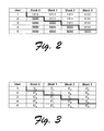
- An example of fingerprinting word assignments is shown in Fig. 2 for five users. Each row corresponds to a user and shows blocks that form the fingerprinting word for that user. For example, user 1 has a fingerprinting word "1111111111111111 ", user 2 has a fingerprinting word "00001111111111111111 ", and so on for each of the users.
- the collection of the fingerprinting words for all of the users defines a step structure that is illustrated by the bold line through the table. This stepped structure is instrumental in ascertaining potential colluders as will become apparent below.
- Each fingerprinting word is divided into a number of blocks that, in turn, include a plurality of bits.
- Each of the blocks includes, in this example, four bits.
- the matrix that is defined by the fingerprinting word assignments is known as a " ⁇ -code". As there can be many, many users, the ⁇ -code necessary to provide fingerprinting words for all of the users will be quite large.
- a single permutation of the columns of the ⁇ -code is performed before embedding an object with a fingerprint word.
- An exemplary permutation is shown in Table 1 below where the order of the blocks is changed. For simplicity, the permutation as represented in the table above occurs over whole blocks. In reality, the permutation occurs at the bit level. For example, the column of leftmost bits might be moved to bit position 12. This permutation is uniform for all of the users and is known only to the encoder or embedder and the decoder: Table 1 User Block 2 Block 1 Block 3 Block 0 1 1111 1111 1111 1111 2 1111 1111 1111 0000 3 1111 0000 1111 0000 4 0000 0000 1111 0000 5 0000 0000 0000 0000 0000
- an "object” is any digital data that is suitable for fingerprinting. Examples of such objects include, without limitation, documents, music, and video.
- an illegal copy of a protected object is made, a user will typically attempt to alter their fingerprinting word so as to avoid detection.
- the BS-system is directed to ascertaining, with a desirable degree of certainty, the identity of one or more users that may have collaborated in the altering of a protected object. This is done by examining the altered object.
- the notation x ⁇ I denotes the restriction of word x to the bit locations of I.
- W(x) denote the Hamming weight of the string x .
- the Hamming weight of a binary string of 1's and 0's is the number of 1's in the string.
- the string is composed of +1's and -1's, we could define it to be the number of +1's in the string.
- the BS-system employs a first algorithm that is directed to finding a subset of a coalition that produced an altered object x .
- an altered object has been produced by two or more users and an attempt is going to be made to identify a subset of users that likely produced the object x .
- a fingerprinting word Recall that each user is assigned a unique permuted fingerprinting word, an example of which is given in Table 1 above. Because each user is assigned a unique fingerprinting word, certain aspects of the fingerprinting word will be unique to each user. For example, a unique aspect of user 1's fingerprinting word in Fig.
- block 0 comprises all 1's.
- Each of the other users has all 0's in their corresponding block 0.
- the marking assumption which states that users cannot modify "unseen” bits
- none of the bits in block 0 will be modified. Accordingly, all of the bits in block 0 will be 0 and user 1 can be ruled out as a colluder.
- any of the bits in block 0 of the altered object x are determined to be 1, then user 1 can be incriminated as a colluder.
- the bits of block 0 are only capable of being "seen” by a collusion that includes user 1 because they are different from the bits in block 0 for all of the other users.
- the first algorithm simply looks at the fingerprinting word in the altered object and attempts to identify, with a desired degree of certainty, which users are possible candidates for incrimination given that certain bits or blocks have been modified. It does this by considering the Hamming weight of particular blocks that are or can be uniquely seen by particular users.
- step function that is defined for user 3 by blocks 1 and 2.
- This step function is unique for user 3 at the location of blocks 1 and 2. That is, all of the other users, either above or below user 3 have, respectively, all 1's or all 0's in their blocks 1 and 2.
- the algorithm looks for this unique step function or some semblance thereof for users other than the first and last users. For the first and last users, the algorithm simply looks for the unique bits in the blocks that are unique for the first and last users. When a step function (or unique bits) are located, a corresponding user can be incriminated. In this example, since the step function still exists for user 3, user 3 can be incriminated. This can be mathematically represented as follows ( ⁇ is the incrimination error probability):
- the second algorithm of the BS-system is directed to incriminating a user or colluder without having to use such a large ⁇ -code.
- c represent the number of colluders that are desired to be defended against.
- a ⁇ -code is then selected to have 2 c rows. In this system each row is also referred to as a "color”. So, for example, if one wants to defend against 20 colluders, then a ⁇ -code is selected that has 40 rows or colors.
- Each row or color in the ⁇ -code comprises a plurality of blocks that make up a ⁇ -symbol.
- Each color or ⁇ -symbol is treated as a letter in an alphabet that is defined by the ⁇ -code.
- the letters in the alphabet are then used to build unique fingerprinting words for each of the users of the protected object. That is, fingerprinting words contain L colors or ⁇ -symbols, where L is a number that is selected to be large enough so that, given the number of users that are to be assigned fingerprinting words, each is assured of being assigned a unique fingerprinting word.
- the BS-system builds a word or vector by selecting, at random, one and only one color from each color set.
- a word might be built by selecting color 1 from the color set associated with the first ⁇ symbol, color 4 from the color set associated with the second ⁇ symbol, and color 6 from the color set associated with the third ⁇ symbol.
- the word that is built is as follows: ⁇ 1 ⁇ 4 ⁇ 6 .
- the user having a fingerprinting word that is closest to this word is incriminated. More detailed information on the BS-system and its proofs can be found in the article referenced above. Algorithm 2 is summarized just below.
- the length in bits of the fingerprinting word or sequence is given by the following equation: O(c 4 log(N/ ⁇ ) log(1/ ⁇ )), where "c" is the size of the collusion, "N” is the number of users, and ⁇ is the incrimination error probability.
- c is the size of the collusion
- N is the number of users
- ⁇ is the incrimination error probability.
- aspects of the BS-system are exploited in conjunction with the use of spread spectrum technology.
- a spread spectrum sequence is associated with individual blocks of individual fingerprint words.
- the spread spectrum sequence utilizes a data structure called a "chip" that is embedded in the protected object.
- the use of spread sequences in the embedding process enables redefinition of the relative weight of each block as well as redefinition of a working range (defined below).
- the new weights and working range are utilized in connection with an analysis that increases the robustness of the protectiveness over that of conventional methods and systems.
- This vector can represent pixels in a movie or any type of suitable digital content that is desirable to protect.
- the components of this vector are viewed over some large alphabet size, e.g. m 1 could be an 8-bit byte that can have a value from between -128 to +128.
- Spread spectrum chips x ( x 1 , ...x u ) are utilized that have values that are measured in the same units as the individual components of the protected object vector, but which have values that are small in comparison to the values that the individual vector components can have, e.g. the chips have values that are in ⁇ +1, -1 ⁇ . That is, values of x are selected to be small enough that when they are added to m they are difficult if not impossible to detect.
- a spread sequence can be utilized to embed data symbols that are in ⁇ +1,-1 ⁇ . These embedded data symbols are different from the individual values ⁇ +1, -1 ⁇ that a spread spectrum chip can have, and therefore the notation ⁇ +D, -D ⁇ is utilized to represent the data symbols ⁇ +1, -1 ⁇ so as to avoid confusion.
- the vector m for the object is combined with the appropriate spread spectrum chips. To embed a +D we add the spread sequence as is, while to embed -D we flip the chips (i.e. take the 1s complement of the sequence) of the spread sequence before adding it.
- a "chip” is the smallest of the data structures and refers to a spread spectrum chip.
- the data symbols that are embedded through the use of the spread spectrum chips are in ⁇ +D, -D ⁇ .
- a "block” is composed of d chips, where d represents a parameter that controls the error rate.
- a " ⁇ -symbol” comprises a plurality of blocks.
- a ⁇ -symbol is composed of 2c -1 blocks, where c represents the number of colluders that are desired to be defended against.
- Last of the data structures is the fingerprinting word which is composed of L ⁇ -symbols, where L represents a particular number that is selected to ensure that all of the users in the relevant user universe receive unique fingerprinting words.
- each user is first assigned a unique fingerprinting word.
- the fingerprinting words incorporate a spread sequence rather than the individual bits as in the BS-system.
- each block B i of the ⁇ code in the BS-system is replaced with a suitable spread sequence.
- blocks that are supposed to be a 1 d in the BS-system are replaced with C i
- blocks that are supposed to be 0 d are replaced with the 1s complement C' i .
- An exemplary ⁇ code in accordance with this embodiment is shown in Fig. 3. Once the users have been assigned their fingerprint words, the columns of the ⁇ code are permuted (at the chip level) as discussed above. An object can now be fingerprinted with the fingerprinting words that are defined by the permuted ⁇ code.
- Fig. 4 shows a flow diagram that describes steps in an embedding method in accordance with the described embodiment.
- Step 100 builds or defines a suitable ⁇ -code, an exemplary one of which is shown in Fig. 3.
- Step 102 permutes the columns of the ⁇ -code in a manner that is known only to the embedder and the decoder that will ultimately decode the fingerprints. Permutation of the columns can take place by randomly shuffling the chips for all of the users (the same permutation for all the users). The permutation is the same for all of the users. An example of a suitable permutation was given above.
- step 104 embeds a unique fingerprinting word in each of a number of different objects that are desired to be protected. An example of an embedding process is given just below. After the embedding process, the protected objects can be distributed.
- a spread sequence x ( x 1 , ...x u ) is to be used as an embedded spread sequence.
- ( ⁇ j)[x j , ⁇ ⁇ +1, -1 ⁇ ] and the signal is over a large alphabet whose size is not important for this discussion.
- a first step in the detection process when an object is received is to unpermute the columns that were previously permuted. Recall that after the fingerprinting words are assigned but before an object is embedded, the columns (at the chip level) of the ⁇ -code are randomly permuted. Both the embedder and the detector know the random permutation. After the columns are unpermuted, the chips are detected in the received object.
- Each component, e.g. pixel, a i is compared with the expected unfingerprinted component, e.g.
- each block in a fingerprinting word comprises d chips. These chips were previously detected as described above. With the chips having been detected, the blocks that comprise the fingerprinting word are initially "clipped” in an effort to distinguish between so-called “seen” and “unseen” blocks. Recall that “seen” blocks are those blocks that can be ascertained by two or more users or entities because of their differences. Alternately, “unseen” blocks are those blocks that cannot be “seen” by users because they are identical. Hence, clipping the blocks as described below distinguishes the "seen” and "unseen” blocks.
- a function is defined from which a relative weight can be calculated.
- the function is defined as follows:
- weight assignment and clipping steps can now take place.
- this takes place by receiving, as input, the detected chips z i arranged as blocks of d chips each (B 1 , B 2 , ).
- the output of the weight assignment and clipping steps is the relative weight of each block, with blocks that are likely "unseen” being clipped to their working range value. This can be represented mathematically as follows:
- Fig. 5 shows a flow diagram that describes steps in a weight assignment and clipping method in accordance with the described embodiment, an example of which is given directly above.
- Step 200 gets the first block that is present in a fingerprinting word.
- Step 202 calculates the weight of the first block. In the described embodiment, the weight of a given block is calculated as set forth above.
- Step 204 determines whether the block is likely an "unseen” block and if so, step 206 clips the block's weight to its working range value. If the block is likely "seen", then its weight is as calculated above (step 208).
- Step 210 determines whether there are any additional blocks. If so, the method branches back to step 202.
- a ⁇ -code having a reduced size was defined when the size of the ⁇ -code was considered in light of the number of colluders that were to be defended against.
- each new row or color of the ⁇ -code defined a ⁇ -symbol, and multiple ⁇ -symbols were used to build fingerprinting words for all of the users.
- Each of the fingerprinting words were different and unique.
- the permuted forms of the fingerprinting words are used for embedding in an object to be protected.
- Each of the fingerprinting words when unpermuted and analyzed in accordance with the BS-system's second algorithm yielded a user that likely constituted a colluder.
- a reduced-size ⁇ -code is also defined and includes a plurality of colors or rows.
- the number of colors or rows is a function of the number of colluders c that are desired to be defended against. That is, the number of colors or rows is defined, in this example, to be 2c.
- Each color or row defines a ⁇ -symbol:
- the ⁇ -symbols that are being defined here are, however, very different from the ⁇ -symbols that are defined in the BS-system.
- the presently-described ⁇ -symbols that make up the ⁇ -code each contain spread sequences, rather than collections of bits.
- a fingerprinting word is composed of L ⁇ -symbols, where a ⁇ -symbol is composed of 2c-1 blocks.
- a block is composed of d chips, where a chip is a spread spectrum chip. Given this relationship, the size of a vector that represents the protected object is 2dcL.
- the columns are randomly permuted in a manner that is known to both the embedder and the detector. After permutation of the columns, individual objects that are desired to be protected are embedded with a permuted fingerprinting word that uniquely serves to identify an associated user or entity.
- the manipulated or altered fingerprinting word contains L ⁇ -symbols.
- each of the individual constituent ⁇ -symbols in the altered fingerprinting word is analyzed and a set of one or more likely colors that might be the subject of a collusion is built.
- the fingerprinting word for each of the users or entities is then compared with the matrix.
- each ⁇ -symbol of the user's fingerprinting word is compared with the set of likely colors for the corresponding ⁇ -symbol of the altered fingerprinting word. If the user's ⁇ -symbol coincides with one of the colors in the set, then a counter is incremented. If there is no coincidence, then the counter is not incremented and the next ⁇ -symbol for the user is checked. This process continues until all of the ⁇ -symbols for all of the users have been checked. At this point in the process, all of the users will have a value associated with their counter. The most likely colluder is the user that has the highest counter value.
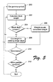
- Fig. 6 shows a flow diagram that describes steps in a detection method in accordance with the described embodiment.
- Step 300 receives a protected object that has a fingerprinting word that has been altered by a user or entity.
- Step 302 unpermutes the columns (at the chip level) of the altered fingerprinting word.
- Step 304 evaluates each of the ⁇ -symbols in the altered fingerprinting word.
- each of the ⁇ -symbols is evaluated by applying Algorithm 3 (above) to the ⁇ -symbol.
- Algorithm 3 produces a matrix (step 306) of likely colors that might be the subject of a collusion.
- Step 308 then gets the first user's fingerprinting word and step 310 evaluates the user's fingerprinting word by comparing the first ⁇ -symbol in the user's fingerprinting word with a set of one or more colors from the matrix.
- the matrix has L columns, each of which corresponds to a different ⁇ -symbol of a fingerprinting word. For any one column, there is a set of one or more colors that are produced by Algorithm 3.
- Step 312 determines whether the user's particular fingerprinting word ⁇ -symbol coincides with one of the colors in the set of colors for the corresponding column in the matrix. If there is a coincidence, then step 314 increments the user's counter. If there is not a coincidence, then step 316 determines whether there are any additional ⁇ -symbols for the user. If there are, then step 318 gets the next ⁇ -symbol and loops back to step 310.
- step 320 determines whether there are any additional users. If there are additional users, then the method loops back to step 308 and gets the new user's fingerprinting word. If there are no additional users, then step 322 selects the user with the highest counter value and incriminates them as a colluder.
- each fingerprinting word has a length L that, in this example, is five ⁇ -symbols long.
- Applying Algorithm 3 to each of the five ⁇ -symbols might yield the following matrix: Matrix Color Implicated Color ⁇ 1 Implicated Color ⁇ 2 Implicated Color ⁇ 3 Implicated Color ⁇ 4 Implicated Color ⁇ 5 1 X X 2 X 3 X X X 4 X 5 X X 6 X X
- each of the last five columns corresponds to an individual ⁇ -symbol in the altered fingerprinting word and contains a number of "X" marks.
- Each "X" indicates, for a particular ⁇ -symbol, a color that might be the subject of a collusion.
- Each ⁇ -symbol in the altered fingerprinting word has a set of one or more colors associated with it. In this example, for the first ⁇ -symbol in the altered fingerprinting word, colors 2 and 3 might be the subject of the collusion. For the second ⁇ -symbol in the fingerprinting word, colors 1 and 5 might be the subject of the collusion, and so on.
- each user's fingerprinting word is compared, ⁇ -symbol by ⁇ -symbol, with the implicated colors for each of the corresponding ⁇ -symbols in the matrix. This comparison is summarized in the table that appears below: User 1 Fingerprinting word 1 1 4 6 5 Counter 1 0 1 1 1 2 User 2 Fingerprinting word 2 5 3 3 4 Counter 2 1 2 3 4 5
- each user has a unique fingerprinting word that is represented numerically by its constituent colors.
- the fingerprinting word for user 1 is as follows [(color 1) (colorl) (color 4) (color 6) (color 5)]. This can also be represented as ( ⁇ 1 ⁇ 1 ⁇ 4 ⁇ 6 ⁇ 5 ).
- each of the user's ⁇ -symbols or colors is checked against the corresponding incriminated colors for the corresponding ⁇ -symbol in the matrix above. If the user's ⁇ -symbol is found in the matrix, then the user's counter is incremented for that ⁇ -symbol.
- the first ⁇ -symbol is defined by color 1.
- Reference to the matrix indicates that, for the first ⁇ -symbol, color 1 is not incriminated. Accordingly, the user's counter is not incremented.
- color 1 is among the set of colors that are implicated for the second ⁇ -symbol of the altered fingerprinting word. Accordingly the counter is incremented by one.
- Similar analysis continues for each of the remaining ⁇ -symbols, and for each of the remaining users. After all of the users have been checked against the matrix, the user with the highest counter value (right most counter column) is selected as a colluder. In this example, user 2 has the higher of the counter values because there are more coincidences between its fingerprinting word and the incriminated colors of the matrix.
Landscapes
- Engineering & Computer Science (AREA)
- Physics & Mathematics (AREA)
- General Physics & Mathematics (AREA)
- Theoretical Computer Science (AREA)
- Multimedia (AREA)
- Signal Processing (AREA)
- Editing Of Facsimile Originals (AREA)
- Image Processing (AREA)
- Television Signal Processing For Recording (AREA)
- Television Systems (AREA)
- Collating Specific Patterns (AREA)
- Optical Communication System (AREA)
Applications Claiming Priority (3)
| Application Number | Priority Date | Filing Date | Title |
|---|---|---|---|
| US09/437,713 US6754364B1 (en) | 1999-10-28 | 1999-10-28 | Methods and systems for fingerprinting digital data |
| US437713 | 1999-10-28 | ||
| PCT/US2000/029843 WO2001031910A1 (en) | 1999-10-28 | 2000-10-27 | Methods and systems for fingerprinting digital data |
Publications (2)
| Publication Number | Publication Date |
|---|---|
| EP1243126A1 EP1243126A1 (en) | 2002-09-25 |
| EP1243126B1 true EP1243126B1 (en) | 2007-06-20 |
Family
ID=23737576
Family Applications (1)
| Application Number | Title | Priority Date | Filing Date |
|---|---|---|---|
| EP00974015A Expired - Lifetime EP1243126B1 (en) | 1999-10-28 | 2000-10-27 | Methods and Apparatus for detecting unauthorized copies of digital objects on the basis of fingerprinting |
Country Status (7)
Families Citing this family (14)
| Publication number | Priority date | Publication date | Assignee | Title |
|---|---|---|---|---|
| US6891958B2 (en) * | 2001-02-27 | 2005-05-10 | Microsoft Corporation | Asymmetric spread-spectrum watermarking systems and methods of use |
| KR20040000954A (ko) * | 2002-06-26 | 2004-01-07 | 삼성전자주식회사 | 이동통신단말기에 있어서 지문인식 방향 선택 방법 |
| US7382905B2 (en) * | 2004-02-11 | 2008-06-03 | Microsoft Corporation | Desynchronized fingerprinting method and system for digital multimedia data |
| US7814564B2 (en) * | 2005-01-07 | 2010-10-12 | University Of Maryland | Method for fingerprinting multimedia content |
| JP4521871B2 (ja) * | 2005-01-18 | 2010-08-11 | 株式会社ダイヤメット | 耐食性、耐摩耗性および高強度を有するモータ式燃料ポンプの軸受 |
| US7760903B2 (en) * | 2005-08-30 | 2010-07-20 | Microsoft Corporation | Tamper-resistant text stream watermarking |
| US20070162761A1 (en) * | 2005-12-23 | 2007-07-12 | Davis Bruce L | Methods and Systems to Help Detect Identity Fraud |
| US8738749B2 (en) | 2006-08-29 | 2014-05-27 | Digimarc Corporation | Content monitoring and host compliance evaluation |
| US8707459B2 (en) | 2007-01-19 | 2014-04-22 | Digimarc Corporation | Determination of originality of content |
| JP4941912B2 (ja) * | 2007-05-28 | 2012-05-30 | 日本放送協会 | 符号データ特定装置及びそのプログラム、並びに、フィンガープリント検出装置及びそのプログラム |
| US9195837B2 (en) * | 2007-11-30 | 2015-11-24 | Hewlett-Packard Development Company, L.P. | Method and system for securely transmitting deterrent data |
| US8312023B2 (en) * | 2007-12-21 | 2012-11-13 | Georgetown University | Automated forensic document signatures |
| US8280905B2 (en) * | 2007-12-21 | 2012-10-02 | Georgetown University | Automated forensic document signatures |
| US8612754B2 (en) | 2011-06-14 | 2013-12-17 | At&T Intellectual Property I, L.P. | Digital fingerprinting via SQL filestream with common text exclusion |
Family Cites Families (48)
| Publication number | Priority date | Publication date | Assignee | Title |
|---|---|---|---|---|
| JP2808672B2 (ja) | 1989-05-31 | 1998-10-08 | 株式会社日立製作所 | オブジェクト指向言語のクラスを用いるメリッド決定方法 |
| US20020009208A1 (en) | 1995-08-09 | 2002-01-24 | Adnan Alattar | Authentication of physical and electronic media objects using digital watermarks |
| US6345104B1 (en) * | 1994-03-17 | 2002-02-05 | Digimarc Corporation | Digital watermarks and methods for security documents |
| JP2761191B2 (ja) * | 1994-08-12 | 1998-06-04 | バンドー化学株式会社 | ベルト伝動方法及びベルト伝動装置 |
| US5999911A (en) | 1995-06-02 | 1999-12-07 | Mentor Graphics Corporation | Method and system for managing workflow |
| US5692129B1 (en) | 1995-07-07 | 1999-08-17 | Novell Inc | Managing application programs in a computer network by using a database of application objects |
| EP0766468B1 (en) * | 1995-09-28 | 2006-05-03 | Nec Corporation | Method and system for inserting a spread spectrum watermark into multimedia data |
| US5802511A (en) | 1996-01-02 | 1998-09-01 | Timeline, Inc. | Data retrieval method and apparatus with multiple source capability |
| EP0888676A1 (en) | 1996-03-12 | 1999-01-07 | LEIGHTON, Frank T. | Watermarking process resilient to collusion attacks |
| US5812134A (en) | 1996-03-28 | 1998-09-22 | Critical Thought, Inc. | User interface navigational system & method for interactive representation of information contained within a database |
| US5970496A (en) | 1996-09-12 | 1999-10-19 | Microsoft Corporation | Method and system for storing information in a computer system memory using hierarchical data node relationships |
| US5875446A (en) | 1997-02-24 | 1999-02-23 | International Business Machines Corporation | System and method for hierarchically grouping and ranking a set of objects in a query context based on one or more relationships |
| US6278991B1 (en) | 1997-08-22 | 2001-08-21 | Sap Aktiengesellschaft | Browser for hierarchical structures |
| US6223145B1 (en) | 1997-11-26 | 2001-04-24 | Zerox Corporation | Interactive interface for specifying searches |
| JP3636272B2 (ja) | 1998-02-09 | 2005-04-06 | 富士通株式会社 | アイコン表示方法、その装置、及び記録媒体 |
| US6442557B1 (en) | 1998-02-27 | 2002-08-27 | Prc Inc. | Evaluation of enterprise architecture model including relational database |
| US6064764A (en) * | 1998-03-30 | 2000-05-16 | Seiko Epson Corporation | Fragile watermarks for detecting tampering in images |
| JP2000003129A (ja) | 1998-04-17 | 2000-01-07 | Digital Vision Laboratories:Kk | 電子透かし埋め込み装置 |
| US6243480B1 (en) | 1998-04-30 | 2001-06-05 | Jian Zhao | Digital authentication with analog documents |
| US6219677B1 (en) * | 1998-05-01 | 2001-04-17 | Emware, Inc. | Split file system |
| US6285366B1 (en) | 1998-06-30 | 2001-09-04 | Sun Microsystems, Inc. | Hierarchy navigation system |
| US6317749B1 (en) | 1998-09-30 | 2001-11-13 | Daman, Inc. | Method and apparatus for providing relationship objects and various features to relationship and other objects |
| US6345100B1 (en) * | 1998-10-14 | 2002-02-05 | Liquid Audio, Inc. | Robust watermark method and apparatus for digital signals |
| JP4130503B2 (ja) * | 1998-11-30 | 2008-08-06 | 株式会社東芝 | 電子透かし埋込み装置 |
| US6564263B1 (en) | 1998-12-04 | 2003-05-13 | International Business Machines Corporation | Multimedia content description framework |
| US6556984B1 (en) | 1999-01-19 | 2003-04-29 | International Business Machines Corporation | Hierarchical string matching using multi-path dynamic programming |
| JP4178647B2 (ja) * | 1999-02-15 | 2008-11-12 | 松下電器産業株式会社 | デジタル情報埋込み・抽出装置および方法並びに当該方法を実行するためのプログラムを記録した記録媒体 |
| JP3607521B2 (ja) * | 1999-03-24 | 2005-01-05 | 株式会社東芝 | 電子透かし埋込装置、電子透かし検出装置、デジタル情報配布装置及び記憶媒体 |
| JP2000329710A (ja) * | 1999-05-17 | 2000-11-30 | Shimadzu Corp | 放射線断層撮影装置、及び、これを用いた物体検査装置 |
| KR100496856B1 (ko) * | 1999-05-20 | 2005-06-22 | 삼성전자주식회사 | 어드레스 확장이 가능한 데이터 처리 시스템 |
| US6754666B1 (en) | 1999-08-19 | 2004-06-22 | A2I, Inc. | Efficient storage and access in a database management system |
| US6289382B1 (en) | 1999-08-31 | 2001-09-11 | Andersen Consulting, Llp | System, method and article of manufacture for a globally addressable interface in a communication services patterns environment |
| JP3735521B2 (ja) * | 1999-09-30 | 2006-01-18 | 株式会社東芝 | 埋め込み符号生成方法及び装置、埋め込み符号検出方法及び装置並びに電子透かし埋め込み装置 |
| US6489970B1 (en) | 1999-11-16 | 2002-12-03 | International Business Machines, Corporation | Means for specifying direct manipulation relationships on hierarchically structured visuals |
| US6807634B1 (en) * | 1999-11-30 | 2004-10-19 | International Business Machines Corporation | Watermarks for customer identification |
| US6463420B1 (en) | 1999-12-30 | 2002-10-08 | General Electric Company | Online tracking of delivery status information over a computer network |
| US20010047385A1 (en) | 1999-12-30 | 2001-11-29 | Jeffrey Tuatini | Passthru to shared service funtionality |
| US6643652B2 (en) | 2000-01-14 | 2003-11-04 | Saba Software, Inc. | Method and apparatus for managing data exchange among systems in a network |
| EP1256046A2 (en) | 2000-02-14 | 2002-11-13 | Geophoenix, Inc. | Methods and apparatus for viewing information in virtual space |
| US20020016974A1 (en) * | 2000-02-16 | 2002-02-07 | Woodland Robert T. | Transgenic, non-human animals containing a coxsackie/adenovirus receptor (CAR) |
| US6636250B1 (en) | 2000-04-12 | 2003-10-21 | Emc Corp | Methods and apparatus for presenting information to a user of a computer system |
| JP3597761B2 (ja) | 2000-07-18 | 2004-12-08 | 株式会社日立製作所 | イオンビーム装置及び試料加工方法 |
| US6708161B2 (en) | 2000-09-26 | 2004-03-16 | I2 Technologies Us, Inc. | System and method for selective database indexing |
| US6891958B2 (en) * | 2001-02-27 | 2005-05-10 | Microsoft Corporation | Asymmetric spread-spectrum watermarking systems and methods of use |
| US6938046B2 (en) | 2001-03-02 | 2005-08-30 | Dow Jones Reuters Business Interactive, Llp | Polyarchical data indexing and automatically generated hierarchical data indexing paths |
| US6990656B2 (en) | 2002-06-27 | 2006-01-24 | Microsoft Corporation | Dynamic metabase store |
| KR100528193B1 (ko) * | 2002-06-29 | 2005-11-15 | 현대자동차주식회사 | 아이에스씨에이 작동 소음 감쇄장치 |
| TWI220910B (en) | 2003-03-14 | 2004-09-11 | Ez Trend Technology Co Ltd | An electric handle |
-
1999
- 1999-10-28 US US09/437,713 patent/US6754364B1/en not_active Expired - Fee Related
-
2000
- 2000-10-27 DE DE60035290T patent/DE60035290T2/de not_active Expired - Lifetime
- 2000-10-27 EP EP00974015A patent/EP1243126B1/en not_active Expired - Lifetime
- 2000-10-27 AU AU12452/01A patent/AU1245201A/en not_active Abandoned
- 2000-10-27 AT AT00974015T patent/ATE365420T1/de not_active IP Right Cessation
- 2000-10-27 WO PCT/US2000/029843 patent/WO2001031910A1/en active IP Right Grant
- 2000-10-27 JP JP2001533740A patent/JP4832692B2/ja not_active Expired - Fee Related
-
2003
- 2003-09-29 US US10/673,970 patent/US7177442B2/en not_active Expired - Fee Related
-
2004
- 2004-12-22 US US11/021,191 patent/US7158655B2/en not_active Expired - Fee Related
- 2004-12-22 US US11/021,192 patent/US7200244B2/en not_active Expired - Fee Related
Non-Patent Citations (1)
| Title |
|---|
| None * |
Also Published As
| Publication number | Publication date |
|---|---|
| JP2003513364A (ja) | 2003-04-08 |
| US20050117777A1 (en) | 2005-06-02 |
| EP1243126A1 (en) | 2002-09-25 |
| DE60035290T2 (de) | 2007-10-04 |
| US20040071314A1 (en) | 2004-04-15 |
| US7200244B2 (en) | 2007-04-03 |
| DE60035290D1 (de) | 2007-08-02 |
| US7177442B2 (en) | 2007-02-13 |
| ATE365420T1 (de) | 2007-07-15 |
| JP4832692B2 (ja) | 2011-12-07 |
| US20050111695A1 (en) | 2005-05-26 |
| US7158655B2 (en) | 2007-01-02 |
| WO2001031910A1 (en) | 2001-05-03 |
| AU1245201A (en) | 2001-05-08 |
| US6754364B1 (en) | 2004-06-22 |
Similar Documents
| Publication | Publication Date | Title |
|---|---|---|
| US7613320B2 (en) | Digital watermark embedding apparatus and method, and digital watermark analysis apparatus, method and program | |
| Celik et al. | Hierarchical watermarking for secure image authentication with localization | |
| EP1243126B1 (en) | Methods and Apparatus for detecting unauthorized copies of digital objects on the basis of fingerprinting | |
| US6807634B1 (en) | Watermarks for customer identification | |
| US8032754B2 (en) | Systems and methods for embedding media forensic identification markings | |
| US7047413B2 (en) | Collusion-resistant watermarking and fingerprinting | |
| JP4037614B2 (ja) | 損失を伴い伝送される画像の保全性確認方法 | |
| JP3937841B2 (ja) | 情報処理装置及びその制御方法 | |
| Dittmann et al. | Combining digital watermarks and collusion secure fingerprints for digital images | |
| Qiao et al. | Watermarking methods for MPEG encoded video: Towards resolving rightful ownership | |
| Li et al. | Constructing a virtual primary key for fingerprinting relational data | |
| JP2005328528A (ja) | デジタル像符牒の処理方法及びシステム | |
| Hadmi et al. | A robust and secure perceptual hashing system based on a quantization step analysis | |
| JP2000350007A (ja) | 電子透かし方法、電子透かし装置および記録媒体 | |
| Das et al. | Cryptanalysis of correlation-based watermarking schemes using single watermarked copy | |
| JP7207627B2 (ja) | 高耐性電子透かし法 | |
| Battiato et al. | Robust watermarking for images based on color manipulation | |
| Hasan et al. | Fragile blockwise image authentication thwarting vector quantization attack | |
| Bhadra et al. | A novel piracy protection scheme for videos using force-induced pixels | |
| Kim et al. | Multi-bits Fingerprinting for Image. | |
| Baqer et al. | Fragile Watermark Based on Singular Value Decomposition | |
| Umar et al. | A System for Multimedia Owner Identification Using PIC | |
| Bedi et al. | Image Index Based Digital Watermarking Techniqu for Ownership Claim and Buyer Fingerprinting | |
| Maitra et al. | Spatial domain digital watermarking with buyer authentication | |
| Al-Omari et al. | Distribution Key in Eight Bit's Color Image Algorithm |
Legal Events
| Date | Code | Title | Description |
|---|---|---|---|
| PUAI | Public reference made under article 153(3) epc to a published international application that has entered the european phase |
Free format text: ORIGINAL CODE: 0009012 |
|
| 17P | Request for examination filed |
Effective date: 20020418 |
|
| AK | Designated contracting states |
Kind code of ref document: A1 Designated state(s): AT BE CH CY DE DK ES FI FR GB GR IE IT LI LU MC NL PT |
|
| AX | Request for extension of the european patent |
Free format text: AL;LT;LV;MK;RO;SI |
|
| 17Q | First examination report despatched |
Effective date: 20021203 |
|
| 17Q | First examination report despatched |
Effective date: 20021203 |
|
| GRAP | Despatch of communication of intention to grant a patent |
Free format text: ORIGINAL CODE: EPIDOSNIGR1 |
|
| RTI1 | Title (correction) |
Free format text: METHODS AND APPARATUS FOR DETECTING UNAUTHORIZED COPIES OF DIGITAL OBJECTS ON THE BASIS OF FINGERPRINTING |
|
| GRAS | Grant fee paid |
Free format text: ORIGINAL CODE: EPIDOSNIGR3 |
|
| GRAA | (expected) grant |
Free format text: ORIGINAL CODE: 0009210 |
|
| AK | Designated contracting states |
Kind code of ref document: B1 Designated state(s): AT BE CH CY DE DK ES FI FR GB GR IE IT LI LU MC NL PT SE |
|
| PG25 | Lapsed in a contracting state [announced via postgrant information from national office to epo] |
Ref country code: LI Free format text: LAPSE BECAUSE OF FAILURE TO SUBMIT A TRANSLATION OF THE DESCRIPTION OR TO PAY THE FEE WITHIN THE PRESCRIBED TIME-LIMIT Effective date: 20070620 Ref country code: CH Free format text: LAPSE BECAUSE OF FAILURE TO SUBMIT A TRANSLATION OF THE DESCRIPTION OR TO PAY THE FEE WITHIN THE PRESCRIBED TIME-LIMIT Effective date: 20070620 |
|
| RBV | Designated contracting states (corrected) |
Designated state(s): AT BE CH CY DE DK ES FI FR GB GR IE IT LI LU MC NL PT SE |
|
| REG | Reference to a national code |
Ref country code: GB Ref legal event code: FG4D |
|
| REG | Reference to a national code |
Ref country code: CH Ref legal event code: EP |
|
| REG | Reference to a national code |
Ref country code: IE Ref legal event code: FG4D |
|
| REF | Corresponds to: |
Ref document number: 60035290 Country of ref document: DE Date of ref document: 20070802 Kind code of ref document: P |
|
| PG25 | Lapsed in a contracting state [announced via postgrant information from national office to epo] |
Ref country code: SE Free format text: LAPSE BECAUSE OF FAILURE TO SUBMIT A TRANSLATION OF THE DESCRIPTION OR TO PAY THE FEE WITHIN THE PRESCRIBED TIME-LIMIT Effective date: 20070920 |
|
| ET | Fr: translation filed | ||
| PG25 | Lapsed in a contracting state [announced via postgrant information from national office to epo] |
Ref country code: AT Free format text: LAPSE BECAUSE OF FAILURE TO SUBMIT A TRANSLATION OF THE DESCRIPTION OR TO PAY THE FEE WITHIN THE PRESCRIBED TIME-LIMIT Effective date: 20070620 |
|
| NLV1 | Nl: lapsed or annulled due to failure to fulfill the requirements of art. 29p and 29m of the patents act | ||
| REG | Reference to a national code |
Ref country code: CH Ref legal event code: PL |
|
| PG25 | Lapsed in a contracting state [announced via postgrant information from national office to epo] |
Ref country code: BE Free format text: LAPSE BECAUSE OF FAILURE TO SUBMIT A TRANSLATION OF THE DESCRIPTION OR TO PAY THE FEE WITHIN THE PRESCRIBED TIME-LIMIT Effective date: 20070620 |
|
| PG25 | Lapsed in a contracting state [announced via postgrant information from national office to epo] |
Ref country code: ES Free format text: LAPSE BECAUSE OF FAILURE TO SUBMIT A TRANSLATION OF THE DESCRIPTION OR TO PAY THE FEE WITHIN THE PRESCRIBED TIME-LIMIT Effective date: 20071001 Ref country code: NL Free format text: LAPSE BECAUSE OF FAILURE TO SUBMIT A TRANSLATION OF THE DESCRIPTION OR TO PAY THE FEE WITHIN THE PRESCRIBED TIME-LIMIT Effective date: 20070620 Ref country code: PT Free format text: LAPSE BECAUSE OF FAILURE TO SUBMIT A TRANSLATION OF THE DESCRIPTION OR TO PAY THE FEE WITHIN THE PRESCRIBED TIME-LIMIT Effective date: 20071120 |
|
| PGFP | Annual fee paid to national office [announced via postgrant information from national office to epo] |
Ref country code: NL Payment date: 20071003 Year of fee payment: 8 |
|
| PLBE | No opposition filed within time limit |
Free format text: ORIGINAL CODE: 0009261 |
|
| STAA | Information on the status of an ep patent application or granted ep patent |
Free format text: STATUS: NO OPPOSITION FILED WITHIN TIME LIMIT |
|
| PG25 | Lapsed in a contracting state [announced via postgrant information from national office to epo] |
Ref country code: DK Free format text: LAPSE BECAUSE OF FAILURE TO SUBMIT A TRANSLATION OF THE DESCRIPTION OR TO PAY THE FEE WITHIN THE PRESCRIBED TIME-LIMIT Effective date: 20070620 Ref country code: GR Free format text: LAPSE BECAUSE OF FAILURE TO SUBMIT A TRANSLATION OF THE DESCRIPTION OR TO PAY THE FEE WITHIN THE PRESCRIBED TIME-LIMIT Effective date: 20070921 |
|
| 26N | No opposition filed |
Effective date: 20080325 |
|
| PGFP | Annual fee paid to national office [announced via postgrant information from national office to epo] |
Ref country code: IE Payment date: 20081015 Year of fee payment: 9 Ref country code: LU Payment date: 20081031 Year of fee payment: 9 Ref country code: MC Payment date: 20081002 Year of fee payment: 9 |
|
| PG25 | Lapsed in a contracting state [announced via postgrant information from national office to epo] |
Ref country code: FI Free format text: LAPSE BECAUSE OF FAILURE TO SUBMIT A TRANSLATION OF THE DESCRIPTION OR TO PAY THE FEE WITHIN THE PRESCRIBED TIME-LIMIT Effective date: 20070620 |
|
| PG25 | Lapsed in a contracting state [announced via postgrant information from national office to epo] |
Ref country code: CY Free format text: LAPSE BECAUSE OF FAILURE TO SUBMIT A TRANSLATION OF THE DESCRIPTION OR TO PAY THE FEE WITHIN THE PRESCRIBED TIME-LIMIT Effective date: 20070620 |
|
| PG25 | Lapsed in a contracting state [announced via postgrant information from national office to epo] |
Ref country code: MC Free format text: LAPSE BECAUSE OF NON-PAYMENT OF DUE FEES Effective date: 20091031 |
|
| PG25 | Lapsed in a contracting state [announced via postgrant information from national office to epo] |
Ref country code: IE Free format text: LAPSE BECAUSE OF NON-PAYMENT OF DUE FEES Effective date: 20091027 |
|
| PG25 | Lapsed in a contracting state [announced via postgrant information from national office to epo] |
Ref country code: LU Free format text: LAPSE BECAUSE OF NON-PAYMENT OF DUE FEES Effective date: 20091027 |
|
| PGFP | Annual fee paid to national office [announced via postgrant information from national office to epo] |
Ref country code: GB Payment date: 20130925 Year of fee payment: 14 |
|
| PGFP | Annual fee paid to national office [announced via postgrant information from national office to epo] |
Ref country code: FR Payment date: 20130924 Year of fee payment: 14 Ref country code: DE Payment date: 20131031 Year of fee payment: 14 |
|
| PGFP | Annual fee paid to national office [announced via postgrant information from national office to epo] |
Ref country code: IT Payment date: 20131016 Year of fee payment: 14 |
|
| REG | Reference to a national code |
Ref country code: DE Ref legal event code: R082 Ref document number: 60035290 Country of ref document: DE Representative=s name: GRUENECKER, KINKELDEY, STOCKMAIR & SCHWANHAEUS, DE |
|
| REG | Reference to a national code |
Ref country code: GB Ref legal event code: 732E Free format text: REGISTERED BETWEEN 20150108 AND 20150114 |
|
| REG | Reference to a national code |
Ref country code: DE Ref legal event code: R081 Ref document number: 60035290 Country of ref document: DE Owner name: MICROSOFT TECHNOLOGY LICENSING, LLC, REDMOND, US Free format text: FORMER OWNER: MICROSOFT CORP., REDMOND, WASH., US Effective date: 20150126 Ref country code: DE Ref legal event code: R082 Ref document number: 60035290 Country of ref document: DE Representative=s name: GRUENECKER, KINKELDEY, STOCKMAIR & SCHWANHAEUS, DE Effective date: 20150126 Ref country code: DE Ref legal event code: R082 Ref document number: 60035290 Country of ref document: DE Representative=s name: GRUENECKER PATENT- UND RECHTSANWAELTE PARTG MB, DE Effective date: 20150126 |
|
| REG | Reference to a national code |
Ref country code: DE Ref legal event code: R119 Ref document number: 60035290 Country of ref document: DE |
|
| GBPC | Gb: european patent ceased through non-payment of renewal fee |
Effective date: 20141027 |
|
| PG25 | Lapsed in a contracting state [announced via postgrant information from national office to epo] |
Ref country code: GB Free format text: LAPSE BECAUSE OF NON-PAYMENT OF DUE FEES Effective date: 20141027 Ref country code: DE Free format text: LAPSE BECAUSE OF NON-PAYMENT OF DUE FEES Effective date: 20150501 |
|
| REG | Reference to a national code |
Ref country code: FR Ref legal event code: ST Effective date: 20150630 |
|
| PG25 | Lapsed in a contracting state [announced via postgrant information from national office to epo] |
Ref country code: IT Free format text: LAPSE BECAUSE OF NON-PAYMENT OF DUE FEES Effective date: 20141027 Ref country code: FR Free format text: LAPSE BECAUSE OF NON-PAYMENT OF DUE FEES Effective date: 20141031 |
|
| REG | Reference to a national code |
Ref country code: FR Ref legal event code: TP Owner name: MICROSOFT TECHNOLOGY LICENSING, LLC, US Effective date: 20150724 |