EP1242322B1 - Verfahren und vorrichtung zum durchtrennen von flachen werkstücken aus sprödbrüchigem material - Google Patents
Verfahren und vorrichtung zum durchtrennen von flachen werkstücken aus sprödbrüchigem material Download PDFInfo
- Publication number
- EP1242322B1 EP1242322B1 EP00981346A EP00981346A EP1242322B1 EP 1242322 B1 EP1242322 B1 EP 1242322B1 EP 00981346 A EP00981346 A EP 00981346A EP 00981346 A EP00981346 A EP 00981346A EP 1242322 B1 EP1242322 B1 EP 1242322B1
- Authority
- EP
- European Patent Office
- Prior art keywords
- focal spot
- contour
- dividing line
- linear
- linear focal
- Prior art date
- Legal status (The legal status is an assumption and is not a legal conclusion. Google has not performed a legal analysis and makes no representation as to the accuracy of the status listed.)
- Expired - Lifetime
Links
Images

Classifications
-
- C—CHEMISTRY; METALLURGY
- C03—GLASS; MINERAL OR SLAG WOOL
- C03B—MANUFACTURE, SHAPING, OR SUPPLEMENTARY PROCESSES
- C03B33/00—Severing cooled glass
- C03B33/09—Severing cooled glass by thermal shock
- C03B33/091—Severing cooled glass by thermal shock using at least one focussed radiation beam, e.g. laser beam
-
- C—CHEMISTRY; METALLURGY
- C03—GLASS; MINERAL OR SLAG WOOL
- C03B—MANUFACTURE, SHAPING, OR SUPPLEMENTARY PROCESSES
- C03B33/00—Severing cooled glass
- C03B33/02—Cutting or splitting sheet glass or ribbons; Apparatus or machines therefor
- C03B33/04—Cutting or splitting in curves, especially for making spectacle lenses
-
- Y—GENERAL TAGGING OF NEW TECHNOLOGICAL DEVELOPMENTS; GENERAL TAGGING OF CROSS-SECTIONAL TECHNOLOGIES SPANNING OVER SEVERAL SECTIONS OF THE IPC; TECHNICAL SUBJECTS COVERED BY FORMER USPC CROSS-REFERENCE ART COLLECTIONS [XRACs] AND DIGESTS
- Y10—TECHNICAL SUBJECTS COVERED BY FORMER USPC
- Y10T—TECHNICAL SUBJECTS COVERED BY FORMER US CLASSIFICATION
- Y10T225/00—Severing by tearing or breaking
- Y10T225/10—Methods
- Y10T225/12—With preliminary weakening
-
- Y—GENERAL TAGGING OF NEW TECHNOLOGICAL DEVELOPMENTS; GENERAL TAGGING OF CROSS-SECTIONAL TECHNOLOGIES SPANNING OVER SEVERAL SECTIONS OF THE IPC; TECHNICAL SUBJECTS COVERED BY FORMER USPC CROSS-REFERENCE ART COLLECTIONS [XRACs] AND DIGESTS
- Y10—TECHNICAL SUBJECTS COVERED BY FORMER USPC
- Y10T—TECHNICAL SUBJECTS COVERED BY FORMER US CLASSIFICATION
- Y10T225/00—Severing by tearing or breaking
- Y10T225/30—Breaking or tearing apparatus
- Y10T225/304—Including means to apply thermal shock to work
Definitions
- the invention relates to a method for cutting flat Workpieces made of brittle material, in particular glass or ceramic, in which a laser beam with a linear focal spot generated by scanning trailing cooling spot along a dividing line with a predetermined contour is moved.
- a preferred application is the cutting of Flat glass.
- the invention further relates to a device for cutting of such a workpiece by means of a laser beam in the form of a linear beam profile with trailing cooling spot.
- One approach to splinters as well as shells and micro cracks avoid, consists in separating glass on the basis of thermally generated mechanical tension. This will create a heat source on the glass is directed, moved at a fixed speed relative to the glass and so such a high thermomechanical stress that the glass cracks forms.
- the necessary property of the heat source, the thermal energy locally, d. H. with an accuracy better than a millimeter, which is typical Cutting accuracy corresponds to being able to position is sufficient Infrared heaters, special gas burners and especially lasers. Have lasers themselves because of their good focusability, good controllability of performance and the possibility of beam shaping and thus the intensity distribution Tried and tested on glass.
- the aforementioned laser beam separation processes differ in particular by configuring the focal spot. This is how the process according to DE 693 04 194 T 2 uses a laser beam with an elliptical cross section trailing cooling spot.
- EP 0 872 303 A 2 describes a laser beam separation process, the one focal spot with a U- or V-shaped contour provides that opens in the separation direction. Also modified from it Contours such as X-shaped focal spots are described.
- the laser beam focal spots have a two-dimensional structure that has proven itself well when performing straight cuts. In the Execution of free-form cuts would have the contour of the dividing line adjusted, curved two-dimensional focal spots and the contour along with the subsequent cooling. This would in particular a coupling of the respective two-dimensional focal spot generating scanner device and the cooling spot device with a Require path control, their implementation due to the large data volumes to be exchanged on the one hand and the required Cutting speeds on the other hand is very problematic.
- a laser beam separation method is known from DE 43 05 107 C 2 in which the laser beam is shaped so that its beam cross section has a linear shape on the surface of the workpiece, in which the ratio of length and width of the beam cross section is adjustable by means of an aperture in the laser beam path.
- This too Procedure is severely limited in its usability. Can't Freeform cuts are made, and, since the cooling only after the complete heating of the dividing line, e.g. by blowing with cold Compressed air to be applied, the known method is suitable practically also only for the described cutting of the press edge from Hollow glasses, in which the hollow glass rotates in the fixed laser beam, whereby first the periphery is heated by the laser beam and then is assisted cooling by inflating the gas.
- the object of the invention is the method described at the outset to guide or to design the associated device so that on relative free form cuts with the laser beam cutting process are feasible.
- the solution is successful Task procedurally in that for performing Free-form cuts with a linear focal spot on the workpiece significant increases in intensity at both ends is generated in the at least 60% of the beam power at the ends of the linear Focal spot is concentrated, and which is moved along the dividing line that even with a curved dividing line both ends lie on the dividing line and the length of which depends on the curvature of the contour of the dividing line is set.
- the method can be described in to carry out advantageously relatively easily if the linear Focal spot is generated by scanning the laser beam.
- the method achieves the object in that an optical Arrangement with a laser beam scanner and a focusing device for generating a linear focal spot with significant Intensity increases at both ends, in which at least 60% of the beam power is concentrated, which is provided over a Profile control is coupled with a numerical path control such that even with curved dividing lines, both ends of the linear focal spot are positioned on the dividing line of the free-form cut and the length of the Focal spot depending on the curvature of the contour of the dividing line is set.
- the optical arrangement can be relative can be carried out easily and common path controls for moving the ends of the focal spot on the dividing line and the Adjustment of the length of the focal spot to the contour of the dividing line used become.
- the Invention further axes coupled to the path control for positioning of the cooling spot in relation to the linear focal spot and that Workpiece are provided.
- the device can be constructed particularly simply if the optical arrangement is one Has scanner with an oscillating mirror. To change the length of the line-shaped focal spot then only needs the amplitude of the Vibration mirror to be changed, so that the profile control and the Path control can be designed relatively easily.
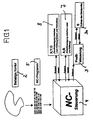
- FIGS. 1 and 2 The principle of severing according to the invention is shown in FIGS. 1 and 2 a flat workpiece made of brittle material, especially of Flat glass, represented by means of the laser beam separation process, with FIG. 1 the basic structure of the control of the motion sequences along a predetermined contour and Fig. 2, the focal spot geometry of the laser beam with the trailing cooling spot and the assignment of the movement axes too the contour control of Fig. 1 shows.
- the separation principle according to the invention is based on a linear one Focal spot 1, at the two ends 1 a and 1 b of which the intensity maxima in the corresponding laser beam profile.
- Intensity increases at the end of the line are, for example, approx. 80% of the total heat energy of the laser beam, which is used for Generation of the thermomechanical stress field is used, i.e. just approx. 20% of the energy is located next to the contour to be cut, the Dividing line 2.
- A is preferably used to generate the linear focal spot 1 known laser beam scanner, e.g. 5 of the above-cited EP 0 872 303 A 2, used, however, one of the two deflecting mirrors can be omitted, since only one axis has to be scanned. Because for the creation of a line, a deflection axis is sufficient, which is an advantage a reduced technical effort is indicated.
- Scanning can also be done using a rotating mirror with simple, flat surfaces Mirror surfaces corresponding to FIG. 6 of the aforementioned EP document and one corresponding, preferably sinusoidal speed curve (polygon wheel) Find application.
- a rotating mirror with simple, flat surfaces Mirror surfaces corresponding to FIG. 6 of the aforementioned EP document and one corresponding, preferably sinusoidal speed curve (polygon wheel) Find application.
- the laser beam By scanning the laser beam with oscillating mirrors or polygon wheels with a sinusoidal speed curve, the laser beam remains in the Reversal points of the scanner movement longer on the one to be separated Workpiece than in the area in between, i.e. when generating the linear focal spot 1 by scanning is typically a Increase in intensity at the end points of line 1.
- the vibration amplitude of the Oscillating mirror determines the line length S in Fig. 1.
- the control of the Scanners are carried out by a profile controller 3 in FIG. 1.
- This controller receives the setpoint for the at the respective position from an NC control the dividing line 2 required length S of the focal spot 1.
- the profile control now controls an oscillator motor 3 a of the oscillating mirror so that it for the required length S of the profile carries out corresponding vibration.
- the Profile control 3 generates an analog voltage oscillation as Setpoint that goes directly from the oscillator motor to an oscillating motion is implemented.
- the setpoint which from the NC control 4 to the Profile control 3 is given, either in the form of an analog constant voltage signal, e.g. 0 - 10 V, the length S is proportional to the amount of voltage, or in the form of a digital value with a resolution of at least 8 bit.
- the actual value feedback shown the measuring system of the oscillator motor 3 a can be omitted if for Oscillator motor a calibration curve in the profile control 3 or the NC control 4 is filed.
- the NC controller 4 controls the NC axes 8 (X, Y and C) and Profile length S via the setpoint specification to the profile controller 3 after a known NC program 5 and corresponding in the NC control stored interpolation algorithms.
- the NC control is able to endpoints 1 a and 1 b of the focal line 1 so to lead them with a maximum deviation of typically follow the dividing line less than 0.2 mm.
- the width of the focal line 1 is determined by the diameter of the focused one Laser beam specified on the workpiece surface.
- the diameter on the workpiece surface is typically between 0.3 mm and several Millimeters.
- Optical elements are used to focus the laser beam used. When choosing the optical elements and the laser, the aim is to the intensity distribution along the line between the end points 1 a and 1 b as evenly as possible without local intensity peaks, and the to keep the maximum intensity in the endpoints as low as possible. To this Most of the laser energy can be coupled into the workpiece, without the glass softening temperature being exceeded. To this end long focal length focusing elements from approx. 300 mm, top hat lenses, Axicons or lasers used with a ring mode or multimode become.
- the width of the line depends on the need Laser power, cooling, material type, material thickness and Feed speed.
- cooling in the form of a cooling spot 6 at a defined distance on the contour 2 to be cut behind the laser profile, i.e. focal line 1, tracked.
- This cooling spot 6 is, for example, by inflating cold air or gas / liquid mixtures generated by a nozzle.
- the advantage of cutting is that there is no subsequent breaking is necessary and thus a manufacturing step is saved.
- Scribing is that at much higher speeds (up to 1000 mm / s) the material is separated almost splinter-free even after breaking was and due to missing micro cracks and mussels a significantly higher edge strength is achieved.
- cooling i.e. the cooling spot 6, very precise in its position relative to the focal line 1.
- the axes A and B also interpolate the axes X, Y, C and the axis specified by the oscillator motor 3 a.
- axes A and B The task of axes A and B is to distance the cooling spot 6 to To keep the starting point 1 b of the focal line 1 constant.
- Profile control 3 can be designed so that the lowest voltage value of the Vibration voltage for the oscillator of the oscillating mirror is always constant remains. In this way, point 1 b is stationary relative to the cooling spot.
- the axes 7 A and B therefore only have to perform short strokes.
- Axes in the sense of the invention are not only intended to be geometrical Axes, but also the associated axes that specify them Movement elements such as actuators and the like can be understood.
Landscapes
- Chemical & Material Sciences (AREA)
- Organic Chemistry (AREA)
- Materials Engineering (AREA)
- Physics & Mathematics (AREA)
- Engineering & Computer Science (AREA)
- Toxicology (AREA)
- Thermal Sciences (AREA)
- Optics & Photonics (AREA)
- Health & Medical Sciences (AREA)
- Re-Forming, After-Treatment, Cutting And Transporting Of Glass Products (AREA)
- Processing Of Stones Or Stones Resemblance Materials (AREA)
- Laser Beam Processing (AREA)
- Finish Polishing, Edge Sharpening, And Grinding By Specific Grinding Devices (AREA)
Description
- Fig. 1
- in einer schematischen Blockschaltbild-Darstellung den prinzipiellen Aufbau der Kontur-Steuerung der erfindungsgemäßen Vorrichtung, und
- Fig. 2
- in einer schematischen, diagrammartigen Darstellung die Form des Brennfleckes und des Kühlfleckes sowie die zugehörigen Bewegungsachsen, die von der Kontursteuerung zu verarbeiten sind.
Claims (6)
- Verfahren zum Durchtrennen von flachen Werkstücken aus sprödbrüchigem Material, bei dem ein Laserstrahl mit einem durch Scannen erzeugten linienförmigen Brennfleck mit nachlaufendem Kühlfleck entlang einer Trennlinie mit vorgegebener Kontur auf dem Werkstück bewegt wird, dadurch gekennzeichnet, daß zum Durchführen von Freiformschnitten auf dem Werkstück ein linienförmiger Brennfleck mit signifikanten Intensitätserhöhungen an beiden Enden erzeugt wird, bei dem mindestens 60 % der Strahlleistung an den Enden des linienförmigen Brennfleckes konzentriert ist, und der so entlang der Trennlinie bewegt wird, daß auch bei gekrümmter Trennlinie beide Enden auf der Trennlinie liegen und dessen Länge dabei abhängig von der Krümmung der Kontur der Trennlinie eingestellt wird.
- Verfahren nach Anspruch 1, dadurch gekennzeichnet, daß 80 % der Strahlleistung an den Enden des linienförmigen Brennfleckes konzentriert ist.
- Verfahren nach Anspruch 1 oder 2, dadurch gekennzeichnet, daß die Strahlleistung abhängig von der Länge des linienförmigen Brennfleckes eingestellt wird.
- Vorrichtung zum Durchführen des Verfahrens nach Anspruch 1 oder 2, dadurch gekennzeichnet, daß eine optische Anordnung mit einem Laserstrahlscanner und einer Fokussionseinrichtung zur Erzeugung eines linienförmigen Brennfleckes (1) mit signifikanten Intensitätserhöhungen an beiden Enden (1 a, 1 b), in denen mindestens 60 % der Strahlleistung konzentriert ist, vorgesehen ist, die über eine Profilsteuerung (3) derart mit einer numerischen Bahnsteuerung (4) mit Achsen zum Positionieren des Brennfleckes (1) gekoppelt ist, daß auch bei gekrümmten Trennlinien beide Enden des linienförmigen Brennfleckes (1) auf der Trennlinie (2) des Freiformschnittes positioniert sind und die Länge des Brennfleckes abhängig von der Krümmung der Kontur der Trennlinie (2) eingestellt ist.
- Vorrichtung nach Anspruch 4, dadurch gekennzeichnet, daß weitere mit der Bahnsteuerung (4) gekoppelte Achsen (7, 8) zum Positionieren des Kühlfleckes (6) in Bezug auf den linienförmigen Brennfleck (1) und das Werkstück vorgesehen sind.
- Vorrichtung nach Anspruch 4 oder 5, dadurch gekennzeichnet, daß die optische Anordnung einen Scanner mit einem Schwingspiegel aufweist.
Applications Claiming Priority (3)
| Application Number | Priority Date | Filing Date | Title |
|---|---|---|---|
| DE19959921 | 1999-12-11 | ||
| DE19959921A DE19959921C1 (de) | 1999-12-11 | 1999-12-11 | Verfahren und Vorrichtung zum Durchtrennen von flachen Werkstücken aus sprödbrüchigem Material |
| PCT/EP2000/012331 WO2001042152A2 (de) | 1999-12-11 | 2000-12-07 | Verfahren und vorrichtung zum durchtrennen von flachen werkstücken aus sprödbrüchigem material |
Publications (2)
| Publication Number | Publication Date |
|---|---|
| EP1242322A2 EP1242322A2 (de) | 2002-09-25 |
| EP1242322B1 true EP1242322B1 (de) | 2003-07-23 |
Family
ID=7932385
Family Applications (1)
| Application Number | Title | Priority Date | Filing Date |
|---|---|---|---|
| EP00981346A Expired - Lifetime EP1242322B1 (de) | 1999-12-11 | 2000-12-07 | Verfahren und vorrichtung zum durchtrennen von flachen werkstücken aus sprödbrüchigem material |
Country Status (7)
| Country | Link |
|---|---|
| US (1) | US6635848B2 (de) |
| EP (1) | EP1242322B1 (de) |
| JP (1) | JP3687070B2 (de) |
| AT (1) | ATE245611T1 (de) |
| DE (2) | DE19959921C1 (de) |
| ES (1) | ES2203535T3 (de) |
| WO (1) | WO2001042152A2 (de) |
Families Citing this family (9)
| Publication number | Priority date | Publication date | Assignee | Title |
|---|---|---|---|---|
| DE19963939B4 (de) * | 1999-12-31 | 2004-11-04 | Schott Spezialglas Gmbh | Verfahren und Vorrichtung zum Durchtrennen von flachen Werkstücken aus sprödbrüchigem Material |
| DE10016628A1 (de) | 2000-04-04 | 2001-10-18 | Schott Glas | Verfahren zum Herstellen von kleinen Dünnglasscheiben und größere Dünnglasscheibe als Halbfabrikat für dieses Herstellen |
| AU2003220835A1 (en) | 2002-03-12 | 2003-09-22 | Mitsuboshi Diamond Industrial Co., Ltd. | Method and system for machining fragile material |
| US6919531B2 (en) | 2002-03-25 | 2005-07-19 | Agilent Technologies, Inc. | Methods for producing glass substrates for use in biopolymeric microarrays |
| DE102004012402B3 (de) * | 2004-03-13 | 2005-08-25 | Schott Ag | Verfahren zum Freiformschneiden von gewölbten Substraten aus sprödbrüchigem Material |
| WO2006017510A2 (en) * | 2004-08-02 | 2006-02-16 | J.P. Sercel Associates, Inc. | System and method for laser machining |
| US8350187B2 (en) * | 2009-03-28 | 2013-01-08 | Electro Scientific Industries, Inc. | Method and apparatus for laser machining |
| US8171753B2 (en) * | 2009-11-18 | 2012-05-08 | Corning Incorporated | Method for cutting a brittle material |
| CN106458693B (zh) * | 2014-02-20 | 2020-06-16 | 康宁股份有限公司 | 用于在柔性薄玻璃中切割多个半径的方法和设备 |
Family Cites Families (7)
| Publication number | Priority date | Publication date | Assignee | Title |
|---|---|---|---|---|
| US5120926A (en) * | 1990-11-26 | 1992-06-09 | General Motors Corporation | Method and apparatus for high speed laser cutting |
| RU2024441C1 (ru) | 1992-04-02 | 1994-12-15 | Владимир Степанович Кондратенко | Способ резки неметаллических материалов |
| DE4305107C2 (de) * | 1993-02-19 | 1995-02-23 | Fraunhofer Ges Forschung | Verfahren und Vorrichtung zum Schneiden eines spröden Körpers mit Laserstrahlung |
| US5776220A (en) * | 1994-09-19 | 1998-07-07 | Corning Incorporated | Method and apparatus for breaking brittle materials |
| MY120533A (en) * | 1997-04-14 | 2005-11-30 | Schott Ag | Method and apparatus for cutting through a flat workpiece made of brittle material, especially glass. |
| KR100283415B1 (ko) * | 1998-07-29 | 2001-06-01 | 구자홍 | 레이저를이용한투명매질의가공방법및장치 |
| DE19915000C2 (de) * | 1999-04-01 | 2002-05-08 | Microlas Lasersystem Gmbh | Vorrichtung und Verfahren zum Steuern der Intensitätsverteilung eines Laserstrahls |
-
1999
- 1999-12-11 DE DE19959921A patent/DE19959921C1/de not_active Expired - Fee Related
-
2000
- 2000-12-07 JP JP2001543456A patent/JP3687070B2/ja not_active Expired - Fee Related
- 2000-12-07 AT AT00981346T patent/ATE245611T1/de active
- 2000-12-07 DE DE50003042T patent/DE50003042D1/de not_active Expired - Lifetime
- 2000-12-07 US US10/130,522 patent/US6635848B2/en not_active Expired - Lifetime
- 2000-12-07 WO PCT/EP2000/012331 patent/WO2001042152A2/de not_active Ceased
- 2000-12-07 ES ES00981346T patent/ES2203535T3/es not_active Expired - Lifetime
- 2000-12-07 EP EP00981346A patent/EP1242322B1/de not_active Expired - Lifetime
Also Published As
| Publication number | Publication date |
|---|---|
| ATE245611T1 (de) | 2003-08-15 |
| US6635848B2 (en) | 2003-10-21 |
| DE50003042D1 (de) | 2003-08-28 |
| JP2003516236A (ja) | 2003-05-13 |
| WO2001042152A3 (de) | 2001-11-01 |
| DE19959921C1 (de) | 2001-10-18 |
| EP1242322A2 (de) | 2002-09-25 |
| WO2001042152A2 (de) | 2001-06-14 |
| JP3687070B2 (ja) | 2005-08-24 |
| ES2203535T3 (es) | 2004-04-16 |
| US20020170895A1 (en) | 2002-11-21 |
Similar Documents
| Publication | Publication Date | Title |
|---|---|---|
| EP1242210B1 (de) | Verfaren und vorrichtung zum durchtrennen von flachen werkstücken aus sprödbrüchigem material | |
| EP0872303B1 (de) | Verfahren und Vorrichtung zum Durchtrennen von flachen Werkstücken aus sprödem Material, insbesondere aus Glas | |
| EP1313673B1 (de) | Verfahren und vorrichtung zum durchschneiden einer flachglasplatte in mehrere rechteckplatten | |
| WO2001032349A1 (de) | Verfahren und vorrichtung zum schnellen schneiden eines werkstücks aus sprödbrüchigem werkstoff | |
| EP1230177A1 (de) | Verfahren und vorrichtung zum schneiden eines flachen werkstückes aus sprödbrüchigem werkstoff | |
| DE19830237C2 (de) | Verfahren und Vorrichtung zum Schneiden eines Werkstückes aus sprödbrüchigem Werkstoff | |
| DE19715537C2 (de) | Verfahren und Vorrichtung zum Durchtrennen von flachen Werkstücken aus sprödem Material, insbesondere aus Glas | |
| DE60102940T2 (de) | Verfahren und vorrichtung zum trennen von glasgegenständen | |
| WO2019197298A1 (de) | VERFAHREN ZUM LASERSCHWEIßEN VON TRANSPARENTEN WERKSTÜCKEN UND ZUGEHÖRIGE LASERBEARBEITUNGSMASCHINE | |
| DE102012003202A1 (de) | Vorrichtung und Verfahren zum Bearbeiten von Werkstücken, insbesondere von Schneiden oder mit Schneiden versehenen Werkstücken, mit einem Nasslaser | |
| DE102005027800A1 (de) | Vorrichtung zum mehrfachen Trennen eines flachen Werkstückes aus einem spröden Material mittels Laser | |
| DE19959921C1 (de) | Verfahren und Vorrichtung zum Durchtrennen von flachen Werkstücken aus sprödbrüchigem Material | |
| WO1994022778A1 (de) | Verfahren zum schneiden von hohlglas | |
| EP3854515A1 (de) | Verfahren zur bearbeitung sprödharter materialien | |
| WO2025132550A1 (de) | Anlage und ein verfahren zum bereichsweisen entschichten einer beschichteten oberfläche eines glaskörpers sowie ein bereichsweise entschichteter glaskörper | |
| DE102007012695A1 (de) | Verfahren und Vorrichtung zur schnellen Ablenkung eines Lichtstrahles auf eine einstellbare Kreisbahn | |
| EP1990168B1 (de) | Verfahren zum laserthermischen Trennen von keramischem oder anderem spröden Plattenmaterial | |
| EP1459116A1 (de) | VERFAHREN ZUM TRENNEN VON LICHTLEITFASERN MITTELS CO sb 2 /sb −LASERSTRAHLUNG | |
| WO2011124627A9 (de) | Verfahren zum bruchtrennen von werkstücken, werkstück und lasereinheit | |
| DE102020000518B3 (de) | Einrichtung zur großflächigen Laserbearbeitung zur Kornorientierung von Elektroblechen | |
| DE10004876C2 (de) | Verfahren und Vorrichtung zum Durchtrennen von flachen Werkstücken aus Quarzkristall in flache Scheiben für Schwingquarze | |
| DE102007014933A1 (de) | Verfahren und Vorrichtung zur schnellen Ablenkung eines Lichtstrahles auf eine einstellbare Längsbahn | |
| DE102022118282A1 (de) | Laserschneidverfahren mit periodisch wiederkehrender überlagerter Strahlablenkung | |
| DE4407756A1 (de) | Verfahren zum Gaslaserschneiden und Vorrichtung zur Durchführung des Verfahrens | |
| DE29823957U1 (de) | Vorrichtung zum Schneiden eines Werkstücks aus sprödbrüchigem Werkstoff |
Legal Events
| Date | Code | Title | Description |
|---|---|---|---|
| PUAI | Public reference made under article 153(3) epc to a published international application that has entered the european phase |
Free format text: ORIGINAL CODE: 0009012 |
|
| 17P | Request for examination filed |
Effective date: 20020410 |
|
| AK | Designated contracting states |
Kind code of ref document: A2 Designated state(s): AT BE CH CY DE DK ES FI FR GB GR IE IT LI LU MC NL PT SE TR |
|
| RIN1 | Information on inventor provided before grant (corrected) |
Inventor name: HAUER, DIRK Inventor name: HOETZEL, BERNDT |
|
| GRAH | Despatch of communication of intention to grant a patent |
Free format text: ORIGINAL CODE: EPIDOS IGRA |
|
| GRAH | Despatch of communication of intention to grant a patent |
Free format text: ORIGINAL CODE: EPIDOS IGRA |
|
| GRAA | (expected) grant |
Free format text: ORIGINAL CODE: 0009210 |
|
| AK | Designated contracting states |
Designated state(s): AT BE CH CY DE DK ES FI FR GB GR IE IT LI LU MC NL PT SE TR |
|
| PG25 | Lapsed in a contracting state [announced via postgrant information from national office to epo] |
Ref country code: TR Free format text: LAPSE BECAUSE OF FAILURE TO SUBMIT A TRANSLATION OF THE DESCRIPTION OR TO PAY THE FEE WITHIN THE PRESCRIBED TIME-LIMIT Effective date: 20030723 Ref country code: FI Free format text: LAPSE BECAUSE OF FAILURE TO SUBMIT A TRANSLATION OF THE DESCRIPTION OR TO PAY THE FEE WITHIN THE PRESCRIBED TIME-LIMIT Effective date: 20030723 Ref country code: IE Free format text: LAPSE BECAUSE OF FAILURE TO SUBMIT A TRANSLATION OF THE DESCRIPTION OR TO PAY THE FEE WITHIN THE PRESCRIBED TIME-LIMIT Effective date: 20030723 |
|
| REG | Reference to a national code |
Ref country code: GB Ref legal event code: FG4D Free format text: NOT ENGLISH |
|
| REG | Reference to a national code |
Ref country code: CH Ref legal event code: EP |
|
| REG | Reference to a national code |
Ref country code: IE Ref legal event code: FG4D Free format text: GERMAN |
|
| REF | Corresponds to: |
Ref document number: 50003042 Country of ref document: DE Date of ref document: 20030828 Kind code of ref document: P |
|
| PG25 | Lapsed in a contracting state [announced via postgrant information from national office to epo] |
Ref country code: GR Free format text: LAPSE BECAUSE OF FAILURE TO SUBMIT A TRANSLATION OF THE DESCRIPTION OR TO PAY THE FEE WITHIN THE PRESCRIBED TIME-LIMIT Effective date: 20031023 Ref country code: DK Free format text: LAPSE BECAUSE OF FAILURE TO SUBMIT A TRANSLATION OF THE DESCRIPTION OR TO PAY THE FEE WITHIN THE PRESCRIBED TIME-LIMIT Effective date: 20031023 Ref country code: SE Free format text: LAPSE BECAUSE OF FAILURE TO SUBMIT A TRANSLATION OF THE DESCRIPTION OR TO PAY THE FEE WITHIN THE PRESCRIBED TIME-LIMIT Effective date: 20031023 |
|
| GBT | Gb: translation of ep patent filed (gb section 77(6)(a)/1977) |
Effective date: 20031025 |
|
| PG25 | Lapsed in a contracting state [announced via postgrant information from national office to epo] |
Ref country code: CY Free format text: LAPSE BECAUSE OF FAILURE TO SUBMIT A TRANSLATION OF THE DESCRIPTION OR TO PAY THE FEE WITHIN THE PRESCRIBED TIME-LIMIT Effective date: 20031207 Ref country code: LU Free format text: LAPSE BECAUSE OF NON-PAYMENT OF DUE FEES Effective date: 20031207 |
|
| PG25 | Lapsed in a contracting state [announced via postgrant information from national office to epo] |
Ref country code: PT Free format text: LAPSE BECAUSE OF FAILURE TO SUBMIT A TRANSLATION OF THE DESCRIPTION OR TO PAY THE FEE WITHIN THE PRESCRIBED TIME-LIMIT Effective date: 20031223 |
|
| PG25 | Lapsed in a contracting state [announced via postgrant information from national office to epo] |
Ref country code: MC Free format text: LAPSE BECAUSE OF NON-PAYMENT OF DUE FEES Effective date: 20031231 |
|
| REG | Reference to a national code |
Ref country code: IE Ref legal event code: FD4D |
|
| ET | Fr: translation filed | ||
| REG | Reference to a national code |
Ref country code: ES Ref legal event code: FG2A Ref document number: 2203535 Country of ref document: ES Kind code of ref document: T3 |
|
| PLBE | No opposition filed within time limit |
Free format text: ORIGINAL CODE: 0009261 |
|
| STAA | Information on the status of an ep patent application or granted ep patent |
Free format text: STATUS: NO OPPOSITION FILED WITHIN TIME LIMIT |
|
| 26N | No opposition filed |
Effective date: 20040426 |
|
| REG | Reference to a national code |
Ref country code: CH Ref legal event code: PUE Owner name: SCHOTT AG Free format text: SCHOTT GLAS#HATTENBERGSTRASSE 10#55122 MAINZ (DE) -TRANSFER TO- SCHOTT AG#HATTENBERGSTRASSE 10#55122 MAINZ (DE) |
|
| REG | Reference to a national code |
Ref country code: GB Ref legal event code: 732E |
|
| NLS | Nl: assignments of ep-patents |
Owner name: SCHOTT AG Effective date: 20060612 |
|
| REG | Reference to a national code |
Ref country code: FR Ref legal event code: TP |
|
| REG | Reference to a national code |
Ref country code: FR Ref legal event code: PLFP Year of fee payment: 16 |
|
| PGFP | Annual fee paid to national office [announced via postgrant information from national office to epo] |
Ref country code: CH Payment date: 20151221 Year of fee payment: 16 Ref country code: DE Payment date: 20151210 Year of fee payment: 16 Ref country code: GB Payment date: 20151221 Year of fee payment: 16 |
|
| PGFP | Annual fee paid to national office [announced via postgrant information from national office to epo] |
Ref country code: ES Payment date: 20151214 Year of fee payment: 16 Ref country code: BE Payment date: 20151221 Year of fee payment: 16 Ref country code: NL Payment date: 20151221 Year of fee payment: 16 Ref country code: FR Payment date: 20151221 Year of fee payment: 16 Ref country code: AT Payment date: 20151222 Year of fee payment: 16 |
|
| PGFP | Annual fee paid to national office [announced via postgrant information from national office to epo] |
Ref country code: IT Payment date: 20151228 Year of fee payment: 16 |
|
| PG25 | Lapsed in a contracting state [announced via postgrant information from national office to epo] |
Ref country code: BE Free format text: LAPSE BECAUSE OF NON-PAYMENT OF DUE FEES Effective date: 20161231 |
|
| REG | Reference to a national code |
Ref country code: DE Ref legal event code: R119 Ref document number: 50003042 Country of ref document: DE |
|
| REG | Reference to a national code |
Ref country code: CH Ref legal event code: PL |
|
| REG | Reference to a national code |
Ref country code: NL Ref legal event code: MM Effective date: 20170101 |
|
| REG | Reference to a national code |
Ref country code: AT Ref legal event code: MM01 Ref document number: 245611 Country of ref document: AT Kind code of ref document: T Effective date: 20161207 |
|
| GBPC | Gb: european patent ceased through non-payment of renewal fee |
Effective date: 20161207 |
|
| PG25 | Lapsed in a contracting state [announced via postgrant information from national office to epo] |
Ref country code: NL Free format text: LAPSE BECAUSE OF NON-PAYMENT OF DUE FEES Effective date: 20170101 |
|
| REG | Reference to a national code |
Ref country code: FR Ref legal event code: ST Effective date: 20170831 |
|
| PG25 | Lapsed in a contracting state [announced via postgrant information from national office to epo] |
Ref country code: CH Free format text: LAPSE BECAUSE OF NON-PAYMENT OF DUE FEES Effective date: 20161231 Ref country code: AT Free format text: LAPSE BECAUSE OF NON-PAYMENT OF DUE FEES Effective date: 20161207 Ref country code: FR Free format text: LAPSE BECAUSE OF NON-PAYMENT OF DUE FEES Effective date: 20170102 Ref country code: LI Free format text: LAPSE BECAUSE OF NON-PAYMENT OF DUE FEES Effective date: 20161231 Ref country code: IT Free format text: LAPSE BECAUSE OF NON-PAYMENT OF DUE FEES Effective date: 20161207 |
|
| PG25 | Lapsed in a contracting state [announced via postgrant information from national office to epo] |
Ref country code: GB Free format text: LAPSE BECAUSE OF NON-PAYMENT OF DUE FEES Effective date: 20161207 Ref country code: DE Free format text: LAPSE BECAUSE OF NON-PAYMENT OF DUE FEES Effective date: 20170701 |
|
| REG | Reference to a national code |
Ref country code: BE Ref legal event code: MM Effective date: 20161231 |
|
| PG25 | Lapsed in a contracting state [announced via postgrant information from national office to epo] |
Ref country code: ES Free format text: LAPSE BECAUSE OF FAILURE TO SUBMIT A TRANSLATION OF THE DESCRIPTION OR TO PAY THE FEE WITHIN THE PRESCRIBED TIME-LIMIT Effective date: 20030723 |
|
| REG | Reference to a national code |
Ref country code: ES Ref legal event code: FD2A Effective date: 20181116 |
|
| PG25 | Lapsed in a contracting state [announced via postgrant information from national office to epo] |
Ref country code: ES Free format text: LAPSE BECAUSE OF FAILURE TO SUBMIT A TRANSLATION OF THE DESCRIPTION OR TO PAY THE FEE WITHIN THE PRESCRIBED TIME-LIMIT Effective date: 20161208 |