EP1241998B1 - Dispositif pour la manipulation et l'identification de petits implants - Google Patents
Dispositif pour la manipulation et l'identification de petits implants Download PDFInfo
- Publication number
- EP1241998B1 EP1241998B1 EP99964747A EP99964747A EP1241998B1 EP 1241998 B1 EP1241998 B1 EP 1241998B1 EP 99964747 A EP99964747 A EP 99964747A EP 99964747 A EP99964747 A EP 99964747A EP 1241998 B1 EP1241998 B1 EP 1241998B1
- Authority
- EP
- European Patent Office
- Prior art keywords
- identifier
- support
- implant
- identification
- small
- Prior art date
- Legal status (The legal status is an assumption and is not a legal conclusion. Google has not performed a legal analysis and makes no representation as to the accuracy of the status listed.)
- Expired - Lifetime
Links
- 239000007943 implant Substances 0.000 title claims abstract description 73
- 239000000463 material Substances 0.000 claims abstract description 16
- 210000000988 bone and bone Anatomy 0.000 claims abstract description 11
- 239000012634 fragment Substances 0.000 claims abstract description 11
- 238000012512 characterization method Methods 0.000 claims abstract description 4
- 238000004659 sterilization and disinfection Methods 0.000 claims description 8
- 230000005489 elastic deformation Effects 0.000 claims description 3
- 238000009877 rendering Methods 0.000 abstract 1
- 238000002513 implantation Methods 0.000 description 7
- 230000001954 sterilising effect Effects 0.000 description 7
- 238000001356 surgical procedure Methods 0.000 description 7
- 238000004519 manufacturing process Methods 0.000 description 4
- 230000000399 orthopedic effect Effects 0.000 description 3
- 230000004308 accommodation Effects 0.000 description 2
- 230000003750 conditioning effect Effects 0.000 description 2
- 230000000694 effects Effects 0.000 description 2
- 229920001971 elastomer Polymers 0.000 description 2
- 239000000806 elastomer Substances 0.000 description 2
- 238000001727 in vivo Methods 0.000 description 2
- 238000003860 storage Methods 0.000 description 2
- 229920002633 Kraton (polymer) Polymers 0.000 description 1
- 239000004698 Polyethylene Substances 0.000 description 1
- 239000004793 Polystyrene Substances 0.000 description 1
- 230000000712 assembly Effects 0.000 description 1
- 238000000429 assembly Methods 0.000 description 1
- 230000000295 complement effect Effects 0.000 description 1
- 230000001010 compromised effect Effects 0.000 description 1
- 230000002950 deficient Effects 0.000 description 1
- 238000005530 etching Methods 0.000 description 1
- 239000011521 glass Substances 0.000 description 1
- 238000012423 maintenance Methods 0.000 description 1
- 238000011017 operating method Methods 0.000 description 1
- -1 polyethylene Polymers 0.000 description 1
- 229920000573 polyethylene Polymers 0.000 description 1
- 229920002223 polystyrene Polymers 0.000 description 1
- 230000001105 regulatory effect Effects 0.000 description 1
- 230000000717 retained effect Effects 0.000 description 1
- 238000003892 spreading Methods 0.000 description 1
- 125000000383 tetramethylene group Chemical group [H]C([H])([*:1])C([H])([H])C([H])([H])C([H])([H])[*:2] 0.000 description 1
- 229920002725 thermoplastic elastomer Polymers 0.000 description 1
Images



Classifications
-
- A—HUMAN NECESSITIES
- A61—MEDICAL OR VETERINARY SCIENCE; HYGIENE
- A61B—DIAGNOSIS; SURGERY; IDENTIFICATION
- A61B50/00—Containers, covers, furniture or holders specially adapted for surgical or diagnostic appliances or instruments, e.g. sterile covers
- A61B50/20—Holders specially adapted for surgical or diagnostic appliances or instruments
-
- A—HUMAN NECESSITIES
- A61—MEDICAL OR VETERINARY SCIENCE; HYGIENE
- A61B—DIAGNOSIS; SURGERY; IDENTIFICATION
- A61B90/00—Instruments, implements or accessories specially adapted for surgery or diagnosis and not covered by any of the groups A61B1/00 - A61B50/00, e.g. for luxation treatment or for protecting wound edges
- A61B90/90—Identification means for patients or instruments, e.g. tags
- A61B90/94—Identification means for patients or instruments, e.g. tags coded with symbols, e.g. text
-
- A—HUMAN NECESSITIES
- A61—MEDICAL OR VETERINARY SCIENCE; HYGIENE
- A61B—DIAGNOSIS; SURGERY; IDENTIFICATION
- A61B17/00—Surgical instruments, devices or methods
- A61B17/56—Surgical instruments or methods for treatment of bones or joints; Devices specially adapted therefor
- A61B17/58—Surgical instruments or methods for treatment of bones or joints; Devices specially adapted therefor for osteosynthesis, e.g. bone plates, screws or setting implements
- A61B17/68—Internal fixation devices, including fasteners and spinal fixators, even if a part thereof projects from the skin
- A61B17/84—Fasteners therefor or fasteners being internal fixation devices
- A61B17/86—Pins or screws or threaded wires; nuts therefor
- A61B17/865—Packages or dispensers for bone screws or threaded wires
Definitions
- the present invention relates to an identifier device for the handling and identification of small implants (screws or other) used in restorative surgery (orthopedic surgery, maxillofacial surgery, osteosynthesis, etc.).
- the identifier device makes it possible to identify and follow the route of a dimension implant very small (for example of the order of 1 to 2 mm), from its manufacture to its implantation on a patient.
- surgeons or their assistants practicing in the operating theater can, on the one hand, easily grasp the small implants such as screws used for coaptation of bone fragments or others, and, on the other hand, read and report the number of these on the files of the patients.
- the manipulation must be the most indirect possible (while remaining easy) not to contaminate said implant.
- the identification number assigned to each implant or each batch of implants most often includes a succession of several digits and / or letters, and engraving this number directly on the implants, if it is possible and in common use for relatively large implants, becomes practically impossible on implants of very small size, for lack of square. Assuming microgravure is possible in some cases, reading easy of this number for example by the surgeon or by one of his assistants, during operation would remain impossible, whether with the naked eye or with the help a magnifying glass. Another possibility might be to use the small space available on each implant to engrave signs of recognition occupying a very small area, in code form but again, reading this code by medical staff without specialized equipment for decoding is impossible.
- EP-A2-0 736 464 shows the characteristics of the preamble of claim 1.
- the object of the invention is in particular to remedy the disadvantages above.
- an identifier device comprising a small implant and a matched identifier support, the latter comprising a body executed, at least in part, in a material having an elastic deformation capacity, this body comprising a housing retender, for example a constrictor housing, of a shape appropriate to that of the small implant matched to said support, and in which is housed, at least partially, this implant, said support further comprising a means of characterization allowing its identification and, consequently, recognition of the matched implant to said identifier medium.
- each implant is clipped into a identifier support which presents, for example on one of its faces and easily readable way, the registration of the information necessary for the identification of the implant he is wearing.
- Identifier / implant support couples can be delivered in bulk, then placed in lockers or containers for Steam sterilization at 138 ° C in an autoclave oven.
- Support couples identifier / implant can be sterilized as many times as necessary without losing the information identifying the implant.
- the device according to the invention greatly facilitates the identification and manipulation of small implants Surgical.
- the identifying device according to the invention also allows the maintenance of the material in place in the container, in particular during the transport of this last.
- a very important advantage of the identifier device according to the invention is it allows to arrange, on the external surface of the support, a beach large enough to engrave a number or other landmark easily readable, intraoperatively, by surgeons or their assistants, that is to say at the time of implantation of the implants. We understand this possibility greatly facilitates the achievement of the traceability imposed by the regulatory texts.
- the identification device also makes it possible advantageous manipulation of the implant by means of sterile instruments, without touch and therefore without contaminating it, for example when setting up implants received in bulk in the lockers.
- the support of the device identifier comprises a lateral slot opening into the retaining housing of said support, the edges of this slot being removable or close together thanks to the elasticity of the material.
- the implant or other small object can be easily engaged and almost instantly in the constrictor housing of the support or cleared all as easily and quickly from this accommodation.
- the support of the device identifier has a lateral recess arranged in alignment with the housing constrictor and in which opens this one.
- the implant such as screw or other can be grasped and easily cleared from its matched support by means of an appropriate instrument such as a previously sterilized forceps or tweezers, which contributes to the preserving the sterile state of said implant.
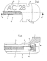
- This device comprises a small implant 7 and a support identifier 1 matched.
- the small implant 7 may be constituted by an osteosynthesis screw used in orthopedic surgery, maxillofacial surgery, or others.
- the identification medium comprises a body 1 made of a material provided with elastic deformation capacity and capable of withstanding high sterilization temperatures in autoclaves, for example in elastomer. It may be performed in whole or at least partly in such material. It may be a thermoplastic elastomer based on polyethylene and butylene (central group) and polystyrene (terminations) for example a kind known under the name "KRATON” (Trademark).
- the body 1 has an elongate shape and has a housing retentor 2 whose axis is oriented longitudinally according to a provision advantageous of the invention, but which could have other orientations, following the applications of it.
- the retentative housing 2 extends over a portion only the length of the body 1.
- the body 1 is provided a longitudinal slot 3 opening outwards, that is to say a slot oriented parallel to the axis of retentative housing 2 into which said outlet slot. It is understood that because of the elasticity of the material in which is executed the body 1, the opposite edges 4a, 4b of the slot 3 can be distant from each other, by applying a spreading force, to enable the positioning a small implant 7 in said housing, or close together, by effect of elasticity, so as to hold said implant in the housing 2.
- the retentive housing 2 has a shape complementary to that of the implant to which it is matched.
- This accommodation can have a conformation to retain the implant, with a small game or without alternatively or additionally, the retentive housing 2 can be constrictor, that is to say capable of exerting a clamping action around the implant, by the elasticity effect of the material. In this case, at rest, the housing presents a diameter slightly less than that of the implant.
- the body Laterally (FIG. 4) or on top (FIG. 7), the body has a surface 5, preferably flat and smooth on which is engraved or otherwise reported, an identification mark 10, for example consisting of a batch number, easily readable. Depending on its location, this surface may occupy a length corresponding approximately to the length of the body 1 or a length less than this.
- an identification mark 10 for example consisting of a batch number, easily readable.
- this surface may occupy a length corresponding approximately to the length of the body 1 or a length less than this.
- an implant 7 has been positioned in a support 1 which is individualized by an identification mark 10, it forms with it an identification set or device, the integrity of which will only be destroyed when the implant is used. implant by the surgeon.
- the identifier support has an open recess 6 extending longitudinally over a length substantially equal to the half-length of the body 1.
- This recess 6 is disposed in the extension of the housing 2 which opens into said recess.
- the latter makes it easy to grasp the implant 7 retained in the body 1, with a surgical clip, to disengage it from its support. It also allows good exposure of the implant to the source of sterilization.
- the implants and their supports thus matched can be engaged by pressure in the dwellings presented by the trays used for sterilization and presentation in the operating room. They remain positioned at their locations during transport due to the pressure exerted by supports on the walls of their homes under the action of the elasticity of the material in which said supports are executed.
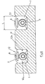
- FIG. 11 shows a plate 11 comprising two grooves longitudinal 12 in which are positioned and maintained two couples identified 1 / screw 7 matched media, for example, for use in the operating room.
- the grooves 12 of the plate 11 have a width L very slightly lower than that of the identifiers, so that these the last can be engaged under a slight pressure between the walls 12a said grooves and then be held in position in the latter thanks to the elasticity of the elastomer in which the body 1 is executed.
- the body 1 of the support identifier present, externally, means for facilitating gripping of the identifier device by means of an instrument of the operating procedure (surgical precelles, for example).
- the body 1 comprises a gripping tab 8 which results, for example, from the provision of a transverse slot 9 that has the free end of the part of the body 1 which delimits the dwelling 2.
- the support assemblies Identifier 1 / implant 7, matched are brought to the operating theater in trays in which they are positioned in a manner determined by pinching, the tongue 8 makes it possible to grasp the assembly including the desired implant and to free him from his home with an appropriate surgical instrument as precious.
- the means of gripping device identifier 1-7 are constituted by two grooves parallels 13 which symmetrically present the opposite lateral faces of the part of the body 1 in which the housing 2 is formed, these grooves being disposed on each side of the slot 3 opening into the latter.
- the jaws of the gripper in the grooves 13 it is easy to disengage the device from the plate and then remove the implant 7 from the support 1, by example by means of another appropriate sterile instrument.
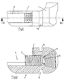
- the housing 2 has, preferably in its median part, a constriction 14 delimited by a flexible circular lip 15.
- This flexible and compressible lip presents a slot 16 communicating with the slot 3 of the body 1.
- the lip or flexible ring split 15 delimits an axial passage of diameter substantially smaller than the diameter of the remaining portion of dwelling 2.
Landscapes
- Health & Medical Sciences (AREA)
- Life Sciences & Earth Sciences (AREA)
- Surgery (AREA)
- Molecular Biology (AREA)
- General Health & Medical Sciences (AREA)
- Biomedical Technology (AREA)
- Heart & Thoracic Surgery (AREA)
- Medical Informatics (AREA)
- Nuclear Medicine, Radiotherapy & Molecular Imaging (AREA)
- Animal Behavior & Ethology (AREA)
- Engineering & Computer Science (AREA)
- Public Health (AREA)
- Veterinary Medicine (AREA)
- Oral & Maxillofacial Surgery (AREA)
- Pathology (AREA)
- Prostheses (AREA)
- Dental Prosthetics (AREA)
- Electrotherapy Devices (AREA)
Description
- soit déjà stérilisé et conditionné dans des boítes stériles lesquelles sont amenées fermées en bloc opératoire pour les implantations ;
- soit non stérilisé, ensuite de quoi il est réparti dans des racks ou plateaux au moyen desquels il est ensuite stérilisé en autoclave, avant d'être amené en bloc opératoire.
- la figure 1 est une vue en perspective avec arrachement partiel d'un premier exemple de réalisation du dispositif identificateur de petits implants selon l'invention ;
- la figure 2 est une vue de face de l'extrémité de la portion du support du dispositif identificateur pourvue du logement constricteur ;
- la figure 3 est une vue en coupe axiale dudit support du dispositif identificateur, considérée suivant la ligne 3-3 de la figure 2 ;
- la figure 4 est une vue en perspective du support du dispositif identicateur, considéré du côté muni de la gravure d'identification ;
- la figure 5 est une vue en plan d'une autre forme de réalisation du dispositif identificateur selon l'invention ;
- la figure 6 est une vue en coupe longitudinale selon la ligne 6-6 de la figure 5;
- la figure 7 est une vue en perspective du support du dispositif identificateur représenté aux figures 5 et 6 ;
- la figure 8 est une vue de face de l'une des extrémités de ce support ;
- la figure 9 est une vue de côté montrant l'appariement d'un support identique et d'une vis présentant des caractéristiques différentes de celle représentée aux figures 5 et 6 ;
- la figure 10 est une vue en coupe longitudinale selon la ligne 10-10 de la figure 9 ;
- la figure 11 est une vue en coupe transversale d'un plateau dans les gorges longitudinales duquel sont positionnés des couples support identificateur/implant selon l'invention.
Lorsqu'un implant 7 a été positionné dans un support 1 individualisé par un repère d'identification 10, il forme avec celui-ci un ensemble ou dispositif identificateur dont l'intégrité ne sera détruite qu'au moment de l'utilisation de l'implant par le chirurgien.
De manière intéressante, le support identificateur comporte un évidement ouvert 6 s'étendant longitudinalement, sur une longueur sensiblement égale à la demi-longueur du corps 1. Cet évidement 6 est disposé dans le prolongement du logement 2 lequel débouche dans ledit évidement. Ce dernier permet de saisir facilement l'implant 7 retenu dans le corps 1, avec une pince chirurgicale, pour le dégager de son support. Il permet en outre une bonne exposition de l'implant à la source de stérilisation.
Claims (8)
- Dispositif identificateur pour la manipulation et l'identification de petits implants utilisés pour la coaptation de fragments d'os et pour l'ostéosynthèse, constitué d'un implant de petite dimension et d'un support identificateur appariés, ce dernier comprenant un corps (1) exécuté, au moins en partie, dans un matériau présentant une capacité de déformation élastique, et muni d'un logement rétenteur (2) de forme appropriée à celle de l'implant (7) de petite dimension apparié audit support et dans lequel se trouve logé, au moins en partie, cet implant ; ledit corps (1) étant pourvu d'une fente (3) débouchant dans ledit logement (2) et ledit support comportant encore un moyen de caractérisation (5-10) permettant son identification et, par conséquent, la reconnaissance dudit implant apparié audit support identificateur, caractérisé en ce que le logement rétenteur (2) du support identificateur comporte un étranglement constricteur (14) délimité par une lèvre souple circulaire (15) et retenant l'implant de petite dimension (7) par une action de serrage s'exerçant autour de ce dernier.
- Dispositif identificateur pour la manipulation et l'identification de petits implants utilisés pour la coaptation de fragments d'os et pour l'ostéosynthèse, selon la revendications 1, caractérisé en ce que la lèvre souple circulaire (15) est fendue et en ce que cette fente (16) communique avec la fente (3) du corps identificateur (1).
- Dispositif identificateur pour la manipulation et l'identification de petits implants utilisés pour la coaptation de fragments d'os et pour l'ostéosynthèse, selon l'une des revendications 1 ou 2, caractérisé en ce que le logement rétenteur (2) s'étend sur une partie seulement de la longueur du corps (1) du support identificateur lequel comporte un évidement (6) ouvert à l'extérieur et disposé dans le prolongement du logement (2) lequel débouche dans ledit évidement.
- Dispositif identificateur pour la manipulation et l'identification de petits implants utilisés pour la coaptation de fragments d'os et pour l'ostéosynthèse, selon l'une quelconque des revendications 1 à 3, caractérisé en ce que le support identificateur (1) présente, extérieurement, un moyen (8-9 ; 13) facilitant sa préhension à l'aide d'un instrument de la procédure opératoire.
- Dispositif identificateur pour la manipulation et l'identification de petits implants utilisés pour la coaptation de fragments d'os et pour l'ostéosynthèse, selon la revendication 4, caractérisé en ce que les moyens destinés à faciliter sa préhension comprennent deux gorges parallèles (13) que présentent, symétriquement, les faces latérales opposées du corps (1) du support identificateur.
- Dispositif identificateur pour la manipulation et l'identification de petits implants utilisés pour la coaptation de fragments d'os et pour l'ostéosynthèse, selon l'une quelconque des revendications 1 à 5, caractérisé en ce que ledit support identificateur est exécuté dans un matériau apte à supporter les températures de stérilisation en autoclave.
- Dispositif identificateur pour la manipulation et l'identification de petits implants utilisés pour la coaptation de fragments d'os et pour l'ostéosynthèse, selon l'une quelconque des revendications 1 à 5, caractérisé en ce que le corps (1) du support identificateur comporte, extérieurement, une surface plane (5) portant un repère (10), par exemple constitué par un numéro de lot.
- Dispositif identificateur pour la manipulation et l'identification de petits implants utilisés pour la coaptation de fragments d'os et pour l'ostéosynthèse selon l'une quelconque des revendications 1 à 7, ledit dispositif comprenant encore un plateau (11) muni de gorges (12) pour le positionnement desdits petits implants et de leurs supports identificateurs, caractérisé en ce que lesdites gorges (12) présentent une largeur (L) très légèrement inférieure à celle du support identificateur (1) de sorte que ces derniers puissent être engagés sous une légère pression manuelle dans lesdites gorges (12) et se trouver ensuite maintenus en position dans ces dernières grâce à l'élasticité du matériau dans lequel le corps (1) est exécuté.
Applications Claiming Priority (1)
| Application Number | Priority Date | Filing Date | Title |
|---|---|---|---|
| PCT/FR1999/003323 WO2001049198A1 (fr) | 1999-12-30 | 1999-12-30 | Dispositif pour la manipulation et l"identification de petits implants |
Publications (2)
| Publication Number | Publication Date |
|---|---|
| EP1241998A1 EP1241998A1 (fr) | 2002-09-25 |
| EP1241998B1 true EP1241998B1 (fr) | 2004-11-10 |
Family
ID=9543319
Family Applications (1)
| Application Number | Title | Priority Date | Filing Date |
|---|---|---|---|
| EP99964747A Expired - Lifetime EP1241998B1 (fr) | 1999-12-30 | 1999-12-30 | Dispositif pour la manipulation et l'identification de petits implants |
Country Status (7)
| Country | Link |
|---|---|
| US (1) | US6802421B1 (fr) |
| EP (1) | EP1241998B1 (fr) |
| AT (1) | ATE281795T1 (fr) |
| AU (1) | AU3049800A (fr) |
| DE (1) | DE69921864T2 (fr) |
| ES (1) | ES2233094T3 (fr) |
| WO (1) | WO2001049198A1 (fr) |
Cited By (3)
| Publication number | Priority date | Publication date | Assignee | Title |
|---|---|---|---|---|
| WO2014102491A1 (fr) * | 2012-12-31 | 2014-07-03 | Neosteo | Ensemble du type comprenant au moins un implant, un prehenseur, et un element de traçabilite de l'implant, et procede de manipulation de maniere traçable de l'implant d'un tel ensemble |
| FR3000379A1 (fr) * | 2012-12-31 | 2014-07-04 | Neosteo | Ensemble comprenant au moins un implant et un prehenseur, et procede de preparation a la pose de l'implant d'un ensemble du type precite |
| FR3000380A1 (fr) * | 2012-12-31 | 2014-07-04 | Neosteo | Ensemble du type comprenant au moins un implant, un prehenseur, et un element de tracabilite de l'implant, et procede de manipulation de maniere tracable de l'implant d'un tel ensemble |
Families Citing this family (12)
| Publication number | Priority date | Publication date | Assignee | Title |
|---|---|---|---|---|
| FI114150B (fi) | 2001-05-17 | 2004-08-31 | Inion Ltd | Kirurgisten kiinnitysvälineiden kiinnitysvälinevarasto ja sovitelma kirurgisten kiinnnitysvälineiden kiinnitysvälinevarastolle |
| US7857129B2 (en) * | 2004-03-07 | 2010-12-28 | Synthes Usa, Llc | Container and carrier system for surgical auxiliary material |
| DE102007011093B3 (de) * | 2007-02-28 | 2008-06-19 | Aesculap Ag & Co. Kg | Chirurgischer Datenträger |
| DE102007011086B3 (de) * | 2007-02-28 | 2008-06-19 | Aesculap Ag & Co. Kg | Chirurgischer Datenträger |
| DE102007015154A1 (de) * | 2007-03-22 | 2008-09-25 | Aesculap Ag & Co. Kg | Haltevorrichtung für ein Implantat |
| ITFI20070155A1 (it) * | 2007-07-11 | 2009-01-12 | Apollonia & Fama Implant S R L | Impianto dentale e relativo confezionamento |
| US8136728B2 (en) * | 2008-04-25 | 2012-03-20 | Warsaw Orthopedic, Inc. | Medical device tracking system with tag and method |
| DE202009002639U1 (de) | 2009-02-26 | 2009-05-07 | Medartis Ag | Träger und Halterung für chirurgische Gegenstände |
| ES2394774T3 (es) * | 2010-05-05 | 2013-02-05 | Biedermann Technologies Gmbh & Co. Kg | Pieza receptora destinada a recibir una barra para su acoplamiento con un elemento de anclaje para hueso, dispositivo de anclaje para hueso y método y herramienta para montar el mismo |
| EP3062728B1 (fr) * | 2013-11-01 | 2021-12-08 | Smith & Nephew, Inc. | Système et procédé de mise en place d'un implant médical et implant possédant une partie de marquage détachable |
| AT523744A1 (de) * | 2020-04-30 | 2021-11-15 | Wolfgang Auf Mag | Verfahren und Vorrichtung zur Dokumentation eines Einsatzes zumindest eines in einer Operation eingesetzten Implantates und/oder dessen Lokalisation |
| AT527065A1 (de) | 2023-03-17 | 2024-10-15 | I T S Gmbh | Vorrichtung zur Dokumentation der Verwendung von eingesetzten Implantaten und Verfahren hierzu |
Family Cites Families (16)
| Publication number | Priority date | Publication date | Assignee | Title |
|---|---|---|---|---|
| DE1074819B (de) * | 1960-02-04 | Radolfzell Dr Julius Walser (Bodensee) | Einrichtung zum bequemen Erfassen von Bohrern und Wurzelkanalinstrumenten und zu deren Einrasten in das zahnärztliche Hand bzw Winkelstück | |
| US2824651A (en) * | 1953-10-20 | 1958-02-25 | Portable Electric Tools Inc | Drill holders |
| DE2434046C3 (de) * | 1974-07-16 | 1979-10-18 | Lothar 7500 Karlsruhe Schwarz | Nadelhalterung für medizinische Spritzen |
| US4253830A (en) * | 1979-06-08 | 1981-03-03 | North Pacific Dental, Inc. | Autoclavable dental bur block |
| SE447445B (sv) * | 1984-12-27 | 1986-11-17 | Branemark Per Ingvar | Steril forpackning for artificiella implantat samt sett for forpackning |
| US5148920A (en) * | 1991-03-18 | 1992-09-22 | Zimmer, Inc. | Package and package insert |
| US5582299A (en) * | 1994-03-01 | 1996-12-10 | Implant Innovations, Inc. | Dental implant packaging |
| US5519931A (en) * | 1994-03-16 | 1996-05-28 | Syncor International Corporation | Container and method for transporting a syringe containing radioactive material |
| AU704070B2 (en) * | 1995-04-07 | 1999-04-15 | Linvatec Corporation | Package retainer for surgical screw |
| US5669501A (en) * | 1996-06-05 | 1997-09-23 | Xomed Surgical Products, Inc. | Package and method for delivering a medical implant |
| DE29705944U1 (de) * | 1997-04-03 | 1997-05-28 | Karl Leibinger Medizintechnik GmbH & Co. KG, 78570 Mühlheim | Implantat-Lagerungssystem |
| DE19758661C2 (de) * | 1997-06-17 | 2002-07-25 | Aesculap Ag & Co Kg | Verpackungseinheit für steril zu verpackende Gegenstände |
| WO1999042049A1 (fr) * | 1998-02-19 | 1999-08-26 | Bionx Implants Oy | Element tenant lieu de monture pour implants chirurgicaux |
| WO2000007510A1 (fr) * | 1998-08-06 | 2000-02-17 | Jordan Medical Llc | Cartouche de vis chirurgicales, magasin/porte-vis et tournevis de type pistolet pour fixation d'os |
| FR2785033B1 (fr) * | 1998-10-21 | 2000-12-01 | Biotech Internat | Support identificateur pour la manipulation et l'identification d'objets de dimension reduite |
| US6527115B2 (en) * | 2001-02-02 | 2003-03-04 | Omnisonics Medical Technologies, Inc. | Dispensation and disposal container for medical devices |
-
1999
- 1999-12-30 WO PCT/FR1999/003323 patent/WO2001049198A1/fr not_active Ceased
- 1999-12-30 US US10/169,019 patent/US6802421B1/en not_active Expired - Lifetime
- 1999-12-30 AT AT99964747T patent/ATE281795T1/de not_active IP Right Cessation
- 1999-12-30 DE DE69921864T patent/DE69921864T2/de not_active Expired - Lifetime
- 1999-12-30 AU AU30498/00A patent/AU3049800A/en not_active Abandoned
- 1999-12-30 ES ES99964747T patent/ES2233094T3/es not_active Expired - Lifetime
- 1999-12-30 EP EP99964747A patent/EP1241998B1/fr not_active Expired - Lifetime
Cited By (5)
| Publication number | Priority date | Publication date | Assignee | Title |
|---|---|---|---|---|
| WO2014102491A1 (fr) * | 2012-12-31 | 2014-07-03 | Neosteo | Ensemble du type comprenant au moins un implant, un prehenseur, et un element de traçabilite de l'implant, et procede de manipulation de maniere traçable de l'implant d'un tel ensemble |
| WO2014102490A1 (fr) * | 2012-12-31 | 2014-07-03 | Neosteo | Ensemble comprenant au moins un implant et un prehenseur, et procede de preparation a la pose de l'implant d'un ensemble du type precite |
| FR3000379A1 (fr) * | 2012-12-31 | 2014-07-04 | Neosteo | Ensemble comprenant au moins un implant et un prehenseur, et procede de preparation a la pose de l'implant d'un ensemble du type precite |
| FR3000380A1 (fr) * | 2012-12-31 | 2014-07-04 | Neosteo | Ensemble du type comprenant au moins un implant, un prehenseur, et un element de tracabilite de l'implant, et procede de manipulation de maniere tracable de l'implant d'un tel ensemble |
| US9629674B2 (en) | 2012-12-31 | 2017-04-25 | Neosteo | Assembly including at least one implant and a gripping device, and method for preparing for fitting the implant of an assembly of the aforementioned type |
Also Published As
| Publication number | Publication date |
|---|---|
| DE69921864T2 (de) | 2005-10-27 |
| AU3049800A (en) | 2001-07-16 |
| ATE281795T1 (de) | 2004-11-15 |
| US6802421B1 (en) | 2004-10-12 |
| ES2233094T3 (es) | 2005-06-01 |
| EP1241998A1 (fr) | 2002-09-25 |
| DE69921864D1 (de) | 2004-12-16 |
| WO2001049198A1 (fr) | 2001-07-12 |
Similar Documents
| Publication | Publication Date | Title |
|---|---|---|
| US8701246B2 (en) | Removable grommet device and method of using thereof | |
| EP1241998A1 (fr) | Dispositif pour la manipulation et l'identification de petits implants | |
| US8739363B2 (en) | Removable grommet device with enlargeable slit and method thereof | |
| JP5192371B2 (ja) | 滅菌処理と適合可能な外科用ねじの保持体及び方法 | |
| EP2083762B1 (fr) | Porte protheses et leurs applications | |
| JP2011025033A (ja) | 医療用器具またはインプラント、特に歯科用器具または歯科インプラントのコンテナ | |
| US12458489B2 (en) | Defined removal site on sterile blister pack | |
| US8915363B2 (en) | Apparatus for retaining medical instruments and related methods | |
| CA2373615A1 (fr) | Recipient de sterilisation | |
| BR102013001690A2 (pt) | Sistema de embalagem para armazenamento, captura e transporte de implantes dentários | |
| US20190231468A1 (en) | Storage assembly for a medical device | |
| US20100252467A1 (en) | Packaging for surgical blade tips | |
| US20130045135A1 (en) | Grommet Device with Pull-Tab and Associated Methods Thereof | |
| US9277967B2 (en) | Universally-sized grommet device and method thereof | |
| FR2785033A1 (fr) | Support identificateur pour la manipulation et l'identification d'objets de dimension reduite | |
| US9452025B2 (en) | Medical instrument holder and method thereof | |
| AU738273B2 (en) | A packaging and component delivery system for use in sterile medical or dental procedures | |
| US10561472B2 (en) | Light reflection and glare preventing medical instrument holding apparatus and related methods | |
| US11406469B2 (en) | No touch sterile medical device packaging |
Legal Events
| Date | Code | Title | Description |
|---|---|---|---|
| PUAI | Public reference made under article 153(3) epc to a published international application that has entered the european phase |
Free format text: ORIGINAL CODE: 0009012 |
|
| 17P | Request for examination filed |
Effective date: 20020705 |
|
| AK | Designated contracting states |
Kind code of ref document: A1 Designated state(s): AT BE CH CY DE DK ES FI FR GB GR IE IT LI LU MC NL PT SE |
|
| AX | Request for extension of the european patent |
Free format text: AL;LT;LV;MK;RO;SI |
|
| GRAP | Despatch of communication of intention to grant a patent |
Free format text: ORIGINAL CODE: EPIDOSNIGR1 |
|
| GRAS | Grant fee paid |
Free format text: ORIGINAL CODE: EPIDOSNIGR3 |
|
| GRAA | (expected) grant |
Free format text: ORIGINAL CODE: 0009210 |
|
| AK | Designated contracting states |
Kind code of ref document: B1 Designated state(s): AT BE CH CY DE DK ES FI FR GB GR IE IT LI LU MC NL PT SE |
|
| PG25 | Lapsed in a contracting state [announced via postgrant information from national office to epo] |
Ref country code: SE Free format text: LAPSE BECAUSE OF FAILURE TO SUBMIT A TRANSLATION OF THE DESCRIPTION OR TO PAY THE FEE WITHIN THE PRESCRIBED TIME-LIMIT Effective date: 20041110 Ref country code: NL Free format text: LAPSE BECAUSE OF FAILURE TO SUBMIT A TRANSLATION OF THE DESCRIPTION OR TO PAY THE FEE WITHIN THE PRESCRIBED TIME-LIMIT Effective date: 20041110 Ref country code: IE Free format text: LAPSE BECAUSE OF FAILURE TO SUBMIT A TRANSLATION OF THE DESCRIPTION OR TO PAY THE FEE WITHIN THE PRESCRIBED TIME-LIMIT Effective date: 20041110 Ref country code: FI Free format text: LAPSE BECAUSE OF FAILURE TO SUBMIT A TRANSLATION OF THE DESCRIPTION OR TO PAY THE FEE WITHIN THE PRESCRIBED TIME-LIMIT Effective date: 20041110 Ref country code: CY Free format text: LAPSE BECAUSE OF FAILURE TO SUBMIT A TRANSLATION OF THE DESCRIPTION OR TO PAY THE FEE WITHIN THE PRESCRIBED TIME-LIMIT Effective date: 20041110 Ref country code: AT Free format text: LAPSE BECAUSE OF FAILURE TO SUBMIT A TRANSLATION OF THE DESCRIPTION OR TO PAY THE FEE WITHIN THE PRESCRIBED TIME-LIMIT Effective date: 20041110 |
|
| REG | Reference to a national code |
Ref country code: GB Ref legal event code: FG4D Free format text: NOT ENGLISH |
|
| REG | Reference to a national code |
Ref country code: CH Ref legal event code: EP |
|
| REG | Reference to a national code |
Ref country code: IE Ref legal event code: FG4D Free format text: FRENCH |
|
| REF | Corresponds to: |
Ref document number: 69921864 Country of ref document: DE Date of ref document: 20041216 Kind code of ref document: P |
|
| PG25 | Lapsed in a contracting state [announced via postgrant information from national office to epo] |
Ref country code: MC Free format text: LAPSE BECAUSE OF NON-PAYMENT OF DUE FEES Effective date: 20041231 |
|
| PG25 | Lapsed in a contracting state [announced via postgrant information from national office to epo] |
Ref country code: LU Free format text: LAPSE BECAUSE OF NON-PAYMENT OF DUE FEES Effective date: 20050110 |
|
| PG25 | Lapsed in a contracting state [announced via postgrant information from national office to epo] |
Ref country code: GR Free format text: LAPSE BECAUSE OF FAILURE TO SUBMIT A TRANSLATION OF THE DESCRIPTION OR TO PAY THE FEE WITHIN THE PRESCRIBED TIME-LIMIT Effective date: 20050210 Ref country code: DK Free format text: LAPSE BECAUSE OF FAILURE TO SUBMIT A TRANSLATION OF THE DESCRIPTION OR TO PAY THE FEE WITHIN THE PRESCRIBED TIME-LIMIT Effective date: 20050210 |
|
| REG | Reference to a national code |
Ref country code: CH Ref legal event code: NV Representative=s name: MICHELI & CIE INGENIEURS-CONSEILS |
|
| GBT | Gb: translation of ep patent filed (gb section 77(6)(a)/1977) |
Effective date: 20050323 |
|
| NLV1 | Nl: lapsed or annulled due to failure to fulfill the requirements of art. 29p and 29m of the patents act | ||
| REG | Reference to a national code |
Ref country code: ES Ref legal event code: FG2A Ref document number: 2233094 Country of ref document: ES Kind code of ref document: T3 |
|
| REG | Reference to a national code |
Ref country code: IE Ref legal event code: FD4D |
|
| PLBE | No opposition filed within time limit |
Free format text: ORIGINAL CODE: 0009261 |
|
| STAA | Information on the status of an ep patent application or granted ep patent |
Free format text: STATUS: NO OPPOSITION FILED WITHIN TIME LIMIT |
|
| 26N | No opposition filed |
Effective date: 20050811 |
|
| PG25 | Lapsed in a contracting state [announced via postgrant information from national office to epo] |
Ref country code: PT Free format text: LAPSE BECAUSE OF NON-PAYMENT OF DUE FEES Effective date: 20050410 |
|
| REG | Reference to a national code |
Ref country code: CH Ref legal event code: PUE Owner name: BIOTECH ORTHO, "SOCIETE PAR ACTIONS SIMPLIFIEE, FR Free format text: FORMER OWNER: BIOTECH INTERNATIONAL (SARL), FR |
|
| REG | Reference to a national code |
Ref country code: FR Ref legal event code: TP Owner name: BIOTECH ORTHO, FR Effective date: 20140225 |
|
| REG | Reference to a national code |
Ref country code: ES Ref legal event code: PC2A Owner name: BIOTECH ORTHO SOCIETE PAR ACTIONS SIMPLIFIEE Effective date: 20140411 |
|
| BECH | Be: change of holder |
Owner name: BIOTECH ORTHO Effective date: 20140411 |
|
| REG | Reference to a national code |
Ref country code: DE Ref legal event code: R082 Ref document number: 69921864 Country of ref document: DE Representative=s name: PATENTANWAELTE STAEGER & SPERLING PARTNERSCHAF, DE Effective date: 20140320 Ref country code: DE Ref legal event code: R081 Ref document number: 69921864 Country of ref document: DE Owner name: TORNIER, FR Free format text: FORMER OWNER: BIOTECH INTERNATIONAL (S.A.R.L.), SALON DE PROVENCE, FR Effective date: 20140320 Ref country code: DE Ref legal event code: R081 Ref document number: 69921864 Country of ref document: DE Owner name: BIOTECH ORTHO, FR Free format text: FORMER OWNER: BIOTECH INTERNATIONAL (S.A.R.L.), SALON DE PROVENCE, FR Effective date: 20140320 |
|
| REG | Reference to a national code |
Ref country code: GB Ref legal event code: 732E Free format text: REGISTERED BETWEEN 20140703 AND 20140709 |
|
| REG | Reference to a national code |
Ref country code: FR Ref legal event code: PLFP Year of fee payment: 17 |
|
| REG | Reference to a national code |
Ref country code: FR Ref legal event code: PLFP Year of fee payment: 18 |
|
| REG | Reference to a national code |
Ref country code: FR Ref legal event code: PLFP Year of fee payment: 19 |
|
| PGFP | Annual fee paid to national office [announced via postgrant information from national office to epo] |
Ref country code: FR Payment date: 20171123 Year of fee payment: 19 Ref country code: DE Payment date: 20171212 Year of fee payment: 19 |
|
| PGFP | Annual fee paid to national office [announced via postgrant information from national office to epo] |
Ref country code: CH Payment date: 20171219 Year of fee payment: 19 Ref country code: GB Payment date: 20171219 Year of fee payment: 19 Ref country code: IT Payment date: 20171213 Year of fee payment: 19 Ref country code: BE Payment date: 20171220 Year of fee payment: 19 |
|
| REG | Reference to a national code |
Ref country code: DE Ref legal event code: R082 Ref document number: 69921864 Country of ref document: DE Representative=s name: PATENTANWAELTE STAEGER & SPERLING PARTNERSCHAF, DE Ref country code: DE Ref legal event code: R081 Ref document number: 69921864 Country of ref document: DE Owner name: TORNIER, FR Free format text: FORMER OWNER: BIOTECH ORTHO, SALON-DE-PROVENCE, FR |
|
| PGFP | Annual fee paid to national office [announced via postgrant information from national office to epo] |
Ref country code: ES Payment date: 20180129 Year of fee payment: 19 |
|
| REG | Reference to a national code |
Ref country code: FR Ref legal event code: TP Owner name: TORNIER, FR Effective date: 20180622 |
|
| REG | Reference to a national code |
Ref country code: DE Ref legal event code: R119 Ref document number: 69921864 Country of ref document: DE |
|
| REG | Reference to a national code |
Ref country code: CH Ref legal event code: PL |
|
| GBPC | Gb: european patent ceased through non-payment of renewal fee |
Effective date: 20181230 |
|
| REG | Reference to a national code |
Ref country code: BE Ref legal event code: MM Effective date: 20181231 |
|
| PG25 | Lapsed in a contracting state [announced via postgrant information from national office to epo] |
Ref country code: FR Free format text: LAPSE BECAUSE OF NON-PAYMENT OF DUE FEES Effective date: 20181231 Ref country code: IT Free format text: LAPSE BECAUSE OF NON-PAYMENT OF DUE FEES Effective date: 20181230 Ref country code: DE Free format text: LAPSE BECAUSE OF NON-PAYMENT OF DUE FEES Effective date: 20190702 |
|
| PG25 | Lapsed in a contracting state [announced via postgrant information from national office to epo] |
Ref country code: BE Free format text: LAPSE BECAUSE OF NON-PAYMENT OF DUE FEES Effective date: 20181231 |
|
| PG25 | Lapsed in a contracting state [announced via postgrant information from national office to epo] |
Ref country code: LI Free format text: LAPSE BECAUSE OF NON-PAYMENT OF DUE FEES Effective date: 20181231 Ref country code: CH Free format text: LAPSE BECAUSE OF NON-PAYMENT OF DUE FEES Effective date: 20181231 Ref country code: GB Free format text: LAPSE BECAUSE OF NON-PAYMENT OF DUE FEES Effective date: 20181230 |
|
| REG | Reference to a national code |
Ref country code: ES Ref legal event code: FD2A Effective date: 20200204 |
|
| PG25 | Lapsed in a contracting state [announced via postgrant information from national office to epo] |
Ref country code: ES Free format text: LAPSE BECAUSE OF NON-PAYMENT OF DUE FEES Effective date: 20181231 |