EP1241614A2 - Appareil et méthode d'ajustement de la position de focalisation dans un système de reconaissance d'iris - Google Patents
Appareil et méthode d'ajustement de la position de focalisation dans un système de reconaissance d'iris Download PDFInfo
- Publication number
- EP1241614A2 EP1241614A2 EP02005944A EP02005944A EP1241614A2 EP 1241614 A2 EP1241614 A2 EP 1241614A2 EP 02005944 A EP02005944 A EP 02005944A EP 02005944 A EP02005944 A EP 02005944A EP 1241614 A2 EP1241614 A2 EP 1241614A2
- Authority
- EP
- European Patent Office
- Prior art keywords
- user
- distance
- camera
- image
- iris recognition
- Prior art date
- Legal status (The legal status is an assumption and is not a legal conclusion. Google has not performed a legal analysis and makes no representation as to the accuracy of the status listed.)
- Granted
Links
Images


Classifications
-
- G—PHYSICS
- G06—COMPUTING; CALCULATING OR COUNTING
- G06V—IMAGE OR VIDEO RECOGNITION OR UNDERSTANDING
- G06V40/00—Recognition of biometric, human-related or animal-related patterns in image or video data
- G06V40/10—Human or animal bodies, e.g. vehicle occupants or pedestrians; Body parts, e.g. hands
- G06V40/18—Eye characteristics, e.g. of the iris
- G06V40/19—Sensors therefor
Definitions
- the present invention relates to an iris recognition system, and particularly to a method for adjusting a camera focus precisely on an iris of a user for increasing the user's convenience and for obtaining a more accurate iris image of the user. More particularly, the present invention relates to a focus position adjusting apparatus and method in an iris recognition system, which enables to adjust the distance between the user and the camera and focus angle between the user and the camera more accurately.
- the iris recognition system is considered to be the best for its high recognition rate compared with the fingerprint recognition, and for its high accuracy.
- the iris recognition system is a technique for authenticating a person by comparing a pre-registered iris data with a new iris data that has been prepared by capturing iris images using a video camera and making iris pattern features into data using an image process technique.
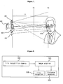
- Figure 1 is a schematic diagram of a general iris recognition system in a related art.
- a distance measurement sensor 109 measures the distance between the user to the system, and a controller 105, having received the distance measurement value through an actuator 107, decides whether the distance measurement value is within the operation limit.
- a control signal is sent out to the actuator 107 to extract iris images. And, the actuator 107 sends an active signal to an external indicator 108 and lets the user know that the system is on.
- a cold mirror 102 blocks a visible ray and passes infrared rays.
- the system indicates whether the iris of the user should be placed to make sure the user's eyes are properly positioned on the optical axis of the camera 103.
- the control device 105 is provided with the distance from the distance measurement sensor 109 to the user, and based on the distance measurement value, it calculates zoom and focus values of the camera 103 and performs zoom in/zoom out and focusing control. Later, the control device 105 adjusts the intensity of an illumination device 106 through the actuator 107 in accordance with the distance measurement value, and photographs the iris image using the camera 103.
- the photographed iris image goes through a signal process to be appropriate for the iris image analysis at a frame grabber 104, and based on the information about the processed iris image, the control device 105 recognizes the iris and decides whether or not to authenticate the user.
- the system uses two cameras for finding out where the user's face and eyes are, and another camera for obtaining the iris image.
- the distance measurement sensor senses a person's approach and focuses the camera based on the inputted images in possession and the focus values outputted from the camera.
- Figure 2 is a block diagram of an autofocus adjusting device using a distance measurement sensor in the prior art.
- a distance measurer 202 measures the distance between the user and the camera 205 at designated regular time intervals using the distance measurement sensor 201, and outputs the distance information successively.
- a distance processor 203 uses the distance information, catches characteristics of the user's movement. More specifically, based on that successive distance information, the distance processor 203 measures the user's movement speed. If the speed is a positive number (+), it means that the user is approaching, and if the speed is a negative number (-), it means the user is going away, and if the absolute speed is within the limit, it means the user stopped moving.
- a camera operation controller 204 uses the information about distance, speed and acceleration provided from the distance processor 203, controls the operation of the camera 205 when the use stands still.
- the camera operation controller 204 adjusts the camera's zoom and focus based on the distance measurement values. Considering that the user can't be perfectly still but keeps moving little bit and the measured distance values are not necessarily the actual distances to the user's eyes, it is rather natural to accept the possibility of measurement error to a certain degree. Therefore, a fine adjustment process is carried out involving the camera operation controller 204, in which the camera operation controller focuses the camera by analyzing the successively inputted iris image from an image controller 206, calculating a focus range therefrom, moving a zoom and focus lens until the focus range becomes appropriate for performing authentication, and continuing the tracking until a maximum value is obtained.
- the image processor 206 detects a possible reflection degree before calculating the focus range, and outputs the glasses reflection information to an illumination controller 207.
- the illumination controller 207 controls the lighting condition of the illumination LED based on the glasses reflection information, and changes the reflected positions from the glasses as well. In this manner, the reflection by the glasses can be prevented and the iris image recognition can be done successfully through an analysis on the iris images obtained from the camera 206.
- one problem of the system is that it depends too heavily on the distance measurement sensor to measure the motion direction and distance of the lens when the camera needs to be focused.
- the distance measurement sensor does not give accurate information on the distance to the user's eyes, which unfortunately does occur very often, the motion direction of the lens could be designated to a wrong direction and the time for adjusting the focus might take longer than expected.
- the system is not that convenient for the user.
- the user has to put his eyes on a position where the distance and the focus adjusting image (using two points) in the iris recognition camera lens are conformed with each other. Once the user gazes the point where two points in the camera converge, the system starts the iris recognition.
- the system gives inconvenience to the user, making him move to a position where two points in a small lens conform to each other while looking at the camera lens.
- an iris recognition apparatus needs to be developed, which enables to measure the distance between the user and the camera more accurately, more conveniently, and more quickly, and to focus the camera automatically.
- Figure 3 is a diagram explaining a relation between the iris recognition camera and the user in terms of position and distance.
- the iris recognition system requires the user to adjust the focal distance (D) and the focal angle accurately while watching the iris recognition camera to get desired iris images.
- the focal distance (D) is Z operating range between user and device, and the focal range is X-Y operating range in figure 3.
- the user is supposed to put his eyes on the place where the distance and the focus adjusting image in the iris recognition camera with a single focus lens (use two circles with different colors) conform to each other.
- the system does not start iris recognition until the user looks at the place where two points in the camera converge.
- the term focus position is intended to indicate that the user's position which can acquire image to recognize iris
- the user is recommended to keep a certain distance from the camera at a certain distance (i.e., 44cm to 48cm), and is encouraged to adjust the focal angle using a blue circle and a white circle in the camera lens.
- the user is supposed to keep looking at the camera and move towards where he can adjust the focal angle until the two circles become one.
- Figure 4(a) illustrates a case where the focal angle is adjusted and (b) illustrates a case where the focal angle went wrong.
- the apparatus encourages the user to practice to get the feeling of the focus position beforehand using a tapeline or something until he becomes intuitively accustomed to the focus position to a certain level. But for the user, it is rather difficult and inconvenient to adjust the focus position, making the white circle out of those two circles looking in the camera lens become one with the blue circle at the same time. Considering the small sized lens and visual difference of the user's eyes, the task seems to be even harder.
- the system uses two lenses and the distance between the LED and the lens is very short, the user, even when he is not at the right front of the lens, could see the LED light, so he cannot be sure whether the focal angle is properly adjusted or not. Further, there is a white point marked on the surface of the lens such that the user can see the LED light from any angle and focus, but this can be an obstacle to obtain good iris images. On top of boring a hole in the reflex mirror to transmit the LED light, if the user looks at the iris recognition camera from a different angle rather than the front, it is very hard to adjust the focal angle since the camera would not look like a circle to the user then.
- an object of the present invention to provide an apparatus and method for obtaining iris images in an iris recognition system more accurately and more conveniently.
- an apparatus for adjusting a focus position in an iris recognition system comprises a camera for a video conference, which acquires images of a user participating in a video conference; an iris recognition camera means, which acquires eye images of the user subject to iris recognition; a distance detection pointer, which projects a specific image to the user for use of distance detection in order to measure a distance between the user and the camera; and a distance calculator, which calculates movement of pointer in the user image by a distance between the pointer image change and the user by performing an image analysis of the user image, which has been photographed by the camera for a video conference and projected by the distance detection pointer.
- Another preferred embodiment of the present invention provides a method for adjusting a focus position in an iris recognition system, the method including the steps of: projecting a designated light for measuring a distance between the user and a camera; acquiring user images including the image projected by the light; and measuring a distance between the user and the camera by extracting the projected image by the light out of the user images and analyzing characteristics of the image.
- Figure 5 is a front view of an optical unit of an iris recognition system according to a first preferred embodiment of the present invention.
- the optical unit 400 in the iris recognition system includes a camera for a video conference 401 for photographing images of a user during the video conference; an iris recognition camera 402 for identifying the user; a distance detection pointer 403 for projecting a designated light to the user; and an illumination device 404 for irradiating an appropriate light when photographing iris images.
- the camera for a video conference 401 is used for acquiring the images of the user (mainly the user's face) for the sake of the video conference.
- the iris recognition camera 402 is used for acquiring eye images of the user necessary to recognize the user's iris.
- the distance detection pointer 403 is used for projecting a specific light to the user (mainly to the user's face) in order to measure the distance between the user and the camera. For instance, the distance detection pointer 403 projects an infrared spot that is usually invisible to the user's eyes.
- the illumination device 404 is used for providing an illumination or light necessary for photographing the iris images to be recognized.
- Figure 6 is a block diagram of an iris recognition system for a video conference according to the first preferred embodiment of the present invention.
- the system includes a camera for the video conference 501 for photographing user images, an image acquirer 502 for acquiring the user images (face) photographed by the camera for the video conference 501, and a distance measurer 503 for extracting a specific image having the projected spot form among the acquired user's face images and for obtaining distance measurement information about the distance between the user and the camera based on a real time analysis of the specific image.
- the system further includes an iris recognition camera 504, an iris image acquirer 505 and an iris recognizer 506 for iris recognition and focus adjustment.
- the camera for a video conference 501 photographs the user, mainly the user's face image.
- This photographed face image includes an infrared spot image to which a light is projected from the pointer for measuring the distance to the user.
- the image acquirer 502 acquires the user's face image together with the infrared spot image that is projected to the face image, and the distance measurer 503 calculates the distance between the user and the camera based on the analysis of the position, the size, and position changes of the acquired infrared spot image on the face.
- a series of the procedures described above that is, acquisition of the user's face image using the iris recognition camera 504, the image acquirer 505, and the iris recognizer 506, extraction of an eye image among the face image, iris recognition from the eye image, and recognition based on the data base by analyzing the recognized iris pattern information, can be accomplished according to the means and methods of the prior art.
- Figure 7 is a diagram explaining a distance measuring method according to the first preferred embodiment of the present invention.
- the distance detection pointer 403 projects an infrared spot image 403a to the user for measuring the distance between the user and the camera.
- this spot image 403a will be the one that is projected to the user's face.
- the camera for a video conference 401 photographs the user's face image.
- the infrared spot image 403a projected to the user's face is acquired as well.
- the position of the infrared spot image 403a on the user's face changes depending on the distance between the user and the camera.
- the size of the infrared spot image 403a also varies depending on the distance between the user and the camera, which is because of the light diffusion.
- the size of the spot image 403 as well as the position of the spot image 403a on the user's face vary accordingly.
- the infrared spot image 403a will move downwards on the user's face, and to upwards in the opposite case.
- the image acquirer (refer to 502 in Figure 7) and the distance measurer (refer to 503 in Figure 7) can also calculate the distance between the user and the camera by analyzing the infrared spot image 403a.
- the image acquirer 502 and the distance measurer 503 can specify the distance for the sake of the user by categorizing the measured distance between the user and the camera into three categories, for example, an appropriate distance, a far distance, and a near distance, and let the user know about this through a designated indicator. For example, if the distance between the user and the camera is appropriate, a green light is turned on, and if the distance is too near, a yellow light is turned on, and if the distance is too far, a red light is turned on so that the user can change his position accordingly.
- a green light is turned on
- if the distance is too near, a yellow light is turned on
- a red light is turned on so that the user can change his position accordingly.
- One more thing is that after the user's position is calculated, it is also possible to obtain a very accurate iris image of the user without moving the user by using zoom in/zoom out and autofocus functions of the iris recognition camera 504.
- the iris recognition domain Based on the calculated distance information, it is decided whether the user entered to the iris recognition domain, a domain where the camera is focused, and if he entered to the accurate iris recognition domain, the iris recognizer is actuated to enable the iris recognition using a single focus lens. And then, the iris recognition camera within the accurate iris recognition domain photographs the user's iris image, and the photographed image is processed to a designated iris image to be compared with other accumulated data later, eventually identifying the user. In fact, this series of the procedures are pretty much identical with the method in the prior art.
- the spot image for measuring the distance is not visible to the user since the invisible infrared rays are applied thereto.
- the present embodiment enables to measure the distance between the user and the camera based on the analysis of the user images which are photographed by the camera for a video conference in the iris recognition system for use of the video conference.
- the present embodiment enables to measure the distance between the user and the camera by projecting an infrared spot image and analyzing where the spot image is going to be positioned on the user's face.
- the present embodiment enables to measure the distance between the user and the camera by using an infrared pointer that is inexpensive yet easy to operate without using a separate distance measurement sensor additionally.
- the present embodiment enables to measure the distance between the user and the camera through a real time analysis of the images photographed by the camera for a video conference, and to focus the camera more automatically and accurately for a better iris recognition based on this distance information.
- Figure 8 is an explanatory diagram of the second preferred embodiment according to the present invention.
- the second embodiment is pretty much same with the first embodiment except that the camera for a video conference together with the iris recognition system is not used in this case. Instead, the iris recognition camera is employed for photographing a large area, if necessary.
- the user's face image is acquired following the same method introduced in the first embodiment, not using the camera for a video conference but using the iris recognition camera. Afterwards, the distance between the user and the camera is measured, and in case the user is within an appropriate distance from the camera, the user's iris image is acquired to identify the qualified user.
- Figure 9 is a front view of an optical unit of an iris recognition system according to the third preferred embodiment of the present invention.
- the iris recognition system 600 depicted in Figure 9 includes an iris recognition camera 601 for photographing the user's iris image, at least one distance detection pointer 602 and 603 for detecting the distance between the user and the camera, and an illumination device 604 for irradiating a light when photographing the iris image.
- the iris recognition camera 601 is used for acquiring the spot image that is needed to measure the distance between the user and the camera, and acquiring the user's eye image to recognize the user's iris.
- the distance detection pointers 602 and 603 are used for projecting the symmetric spot images to the user's face.
- the distance detection pointer projects the invisible infrared spot image to the user.
- an infrared ray light emitting diode IR LED is preferably used for the distance detection pointers 602 and 603.
- the illumination device 604 provides a light necessary for photographing the iris image to be recognized.
- Figure 10 is an exemplary diagram explaining how to array the infrared ray light emitting diode in the third preferred embodiment of the present invention.
- the iris recognition system includes the iris recognition camera 601 inside of the optical unit 600, and the distance detection pointers 602 and 603 being positioned symmetrically in both sides of the camera 601 (refer to Figure 10 (a)). Alternatively, it is possible to place the distance detection pointers 602 and 603 being in 45 degrees symmetric positions with respect to the iris recognition camera 601 (refer to Figure 10 (b) and (c)).
- the system further includes the illumination device 604 for photographing the iris images.
- Figure 11 is a block diagram showing a configuration of the iris recognition system according to the third preferred embodiment of the present invention.
- the iris recognition system includes an iris recognition camera 701 for acquiring images necessary to the distance measurement and iris recognition; an image processor 702 for processing the images that are photographed by the iris recognition camera 701; a controller 704 which includes the distance measurer 703a for measuring the distance between the user and the camera based on the real time analysis of the processed images and the iris recognizer 703b for performing iris recognition on the processed images; an actuator 705, being connected to the controller 704, for driving the iris recognition camera 701, distance detection pointers 706 and 707, and the illuminator 708; at least a pair of distance detection pointers 706 and 707 for projecting a spot image for use of distance measurement under the control of the actuator 705; and an illuminator 708 which actuates under the control of the actuator 705.
- the iris recognition camera 701 generally photographs the user's face image to extract his iris image therefrom. Especially in this embodiment, the iris recognition camera 701 photographs the images for use of distance measurement as well.
- the actuator 705 actuates the distance detection pointers 706 and 706 including the infrared light emitting diode in order to project the infrared spot image to the user's face.
- the iris recognition camera 701 photographs the user's face image to which the infrared spot image is projected.
- the photographed face image includes the infrared spot images that have been projected from the distance measurement pointers IR LED 1 and IR LED2.
- the image processor 702 acquires the infrared spot images projected to the user's face, and analyzes their positions on the face, sizes, position changes and sharpness, helping the distance measurer 703a to be able to calculate the distance between the iris recognition camera and the user. Especially, the reason for putting a pair of infrared light emitting diode symmetrically and getting the symmetric spot images is to make it easier to do the distance measurement by maximizing the location and angle of the projected light, and to get rid of any reflection from things like the glasses.
- the iris recognition camera 701 photographs the images necessary to recognize the iris. After that, the iris recognition camera 701, the image processor 702, the iris recognizer 703b, and the illuminator 708 are used for acquiring, recognizing the iris images, and analyzing the recognized iris pattern information in order. In this manner, it becomes possible to identify the qualified user using the database prepared for the iris recognition.
- Figure 12 is an explanatory diagram explaining the distance measuring method in accordance with the third preferred embodiment of the present invention.
- the optical unit 600 (a front side of the optical system) in the iris recognition system includes the iris recognition camera 601, the distance detection pointers 602 and 603, and the illuminator 604. And, the photographed image 605 includes the spot images 602a and 603b.
- each distance detection pointer 602 and 603 introduce the corresponding spot images 602a and 603a, respectively. Since these spot images are in symmetric positions to each other with respect to each distance detection pointer 602 and 603, the spot images 602a and 603a are also in symmetric positions to each other on the photographed image 605.
- the distance detection pointers 602 and 603 are actuated, and in result, the infrared spot images 602a and 603a are formed on the user.
- the spot images 602a and 603a are projected primarily to the user's face.
- the iris recognition camera 601 then photographs the user's face image. At this time, the infrared spot images 602a and 603a on the user's face are also acquired.
- the location, size and distinctiveness (or sharpness) of the infrared spot images 602a and 603a vary, depending on the distance (D) between the user and the iris recognition camera.
- the size and the sharpness of the infrared spot images 602a and 603a as well as the location, size and brightness of the spot images on the user's face are different in case the distance between the user and the camera is far or near.
- the infrared spot images 602 and 603a tend to be sharper near the focus, and smaller as they become more distant from the operation domain limit of the iris recognition.
- the distance detection pointers 602 and 603 manifest changes in the size, sharpness and location of the two infrared spot images 602a and 603a by crossing them symmetrically, it is easier to track the changes in the two spot images more easily.
- the distance measurer can calculate the distance (D) between the user and the iris recognition camera by analyzing the characteristics described above, and it is confirmed whether or not the user has entered into the iris recognizable domain, the domain where the camera is focused. If he did enter into the iris recognizable domain, the iris recognizer is actuated and starts the iris recognition using a single focus lens.
- the system can specify the distance between the user subject to the measurement and the camera by categorizing the distance into three categories, such as, an appropriate distance, a far distance, and a near distance, and let the user know this through a designated indicator. For example, if the distance between the user and the camera is appropriate, a green light is turned on, and if the distance is too near, a yellow light is turned on, and if the distance is too far, a red light is turned on so that the user can change his position accordingly.
- One more thing to know here is that after the user's position is calculated, it is also possible to obtain a very accurate iris image of the user without moving the user by using zoom in/zoom out and autofocus functions of the iris recognition camera.
- the spot images for measuring the distance are not visible to the user at all since the invisible infrared rays are used. Also, on top of the usage convenience of the infrared rays, another merit of using the infrared rays is that the user does not have to feel insecure about projecting the infrared spot images to his face.
- the system can let the user know whether he is at appropriate distance from the camera, or whether he should move closer to the camera or farther from it. In this way, the system helps the user to find the most appropriate position for photographing his iris and eventually for better iris recognition.
- the present embodiment enables to measure the distance between the user and the camera by projecting a pair of infrared spot images to the user's face, and finding out where the spot images the iris recognition photographed are located on the face.
- a more accurate distance between the user and the camera can be obtained by analyzing how big and bright the infrared spot images.
- the present embodiment of the present invention enables to measure the distance between the user and the camera using an infrared pointer that is inexpensive and easy to operate, without using a separate distance measurement sensor.
- the embodiment enables to measure the distance between the user and the camera through a real time analysis of the images that are photographed by the iris recognition camera. This distance information is used for the system to focus the camera more automatically and accurately for a better iris recognition, or for letting the user know the distance and the direction he should move.
Applications Claiming Priority (4)
| Application Number | Priority Date | Filing Date | Title |
|---|---|---|---|
| KR10-2001-0013376A KR100443674B1 (ko) | 2001-03-15 | 2001-03-15 | 홍채 인식 시스템의 거리 측정방법과 장치 |
| KR2001013376 | 2001-03-15 | ||
| KR2001025993 | 2001-05-12 | ||
| KR10-2001-0025993A KR100434370B1 (ko) | 2001-05-12 | 2001-05-12 | 홍채 인식 시스템의 거리 측정방법과 장치 |
Publications (3)
| Publication Number | Publication Date |
|---|---|
| EP1241614A2 true EP1241614A2 (fr) | 2002-09-18 |
| EP1241614A3 EP1241614A3 (fr) | 2003-12-17 |
| EP1241614B1 EP1241614B1 (fr) | 2006-02-08 |
Family
ID=36120895
Family Applications (1)
| Application Number | Title | Priority Date | Filing Date |
|---|---|---|---|
| EP02005944A Expired - Lifetime EP1241614B1 (fr) | 2001-03-15 | 2002-03-15 | Appareil et méthode d'ajustement de la position de focalisation dans un système de reconaissance d'iris |
Country Status (4)
| Country | Link |
|---|---|
| US (1) | US7095901B2 (fr) |
| EP (1) | EP1241614B1 (fr) |
| JP (1) | JP2002352235A (fr) |
| DE (1) | DE60209050T2 (fr) |
Cited By (12)
| Publication number | Priority date | Publication date | Assignee | Title |
|---|---|---|---|---|
| WO2007096520A1 (fr) * | 2006-02-24 | 2007-08-30 | Sagem Securite | Biodetecteur sans contact |
| CN101681021B (zh) * | 2007-04-06 | 2012-02-01 | 全球仿生光学有限公司 | 大景深成像系统和虹膜识别系统 |
| CN104036256A (zh) * | 2014-06-25 | 2014-09-10 | 兰州大学 | 一种眼球影像采集装置 |
| EP2983107A3 (fr) * | 2014-08-04 | 2016-03-09 | Samsung Electronics Co., Ltd | Dispositif et procédé pour une reconnaissance de l'iris |
| CN107257659A (zh) * | 2015-02-26 | 2017-10-17 | 富士通株式会社 | 电子设备和活体认证程序 |
| CN107633243A (zh) * | 2017-11-10 | 2018-01-26 | 北京上古视觉科技有限公司 | 一种虹膜成像装置以及信息采集系统 |
| WO2018038429A1 (fr) | 2016-08-23 | 2018-03-01 | Samsung Electronics Co., Ltd. | Dispositif électronique comprenant un capteur de reconnaissance d'iris et son procédé de fonctionnement |
| CN108507604A (zh) * | 2018-04-10 | 2018-09-07 | 航天科技控股集团股份有限公司 | 一种全自动指针调整系统 |
| CN109830008A (zh) * | 2019-01-17 | 2019-05-31 | 浙江大华技术股份有限公司 | 一种智能锁报警的方法及装置 |
| WO2021098135A1 (fr) * | 2019-11-21 | 2021-05-27 | 苏州思源科安信息技术有限公司 | Dispositif et procédé d'imagerie optique d'iris de grand champ à longue distance |
| US11179035B2 (en) | 2018-07-25 | 2021-11-23 | Natus Medical Incorporated | Real-time removal of IR LED reflections from an image |
| CN114377302A (zh) * | 2022-03-23 | 2022-04-22 | 杭州高瓴医疗科技有限公司 | 一种红外辅助治疗乳腺癌的仪器 |
Families Citing this family (101)
| Publication number | Priority date | Publication date | Assignee | Title |
|---|---|---|---|---|
| US7271839B2 (en) * | 2001-03-15 | 2007-09-18 | Lg Electronics Inc. | Display device of focal angle and focal distance in iris recognition system |
| KR20030082128A (ko) * | 2002-04-16 | 2003-10-22 | 엘지전자 주식회사 | Pc용 홍채인식 기능이 내장된 마우스 장치 |
| JP4258393B2 (ja) * | 2003-03-13 | 2009-04-30 | 三菱電機株式会社 | 個人識別装置および指紋画像撮像装置、指紋画像取得方法 |
| JP2004295572A (ja) * | 2003-03-27 | 2004-10-21 | Matsushita Electric Ind Co Ltd | 認証対象画像撮像装置及びその撮像方法 |
| JP2007504562A (ja) * | 2003-09-04 | 2007-03-01 | サーノフ コーポレーション | 1つの画像から虹彩認証を行う方法および装置 |
| US7593550B2 (en) | 2005-01-26 | 2009-09-22 | Honeywell International Inc. | Distance iris recognition |
| US7933507B2 (en) | 2006-03-03 | 2011-04-26 | Honeywell International Inc. | Single lens splitter camera |
| US8049812B2 (en) | 2006-03-03 | 2011-11-01 | Honeywell International Inc. | Camera with auto focus capability |
| US8442276B2 (en) | 2006-03-03 | 2013-05-14 | Honeywell International Inc. | Invariant radial iris segmentation |
| US8098901B2 (en) | 2005-01-26 | 2012-01-17 | Honeywell International Inc. | Standoff iris recognition system |
| US8090157B2 (en) * | 2005-01-26 | 2012-01-03 | Honeywell International Inc. | Approaches and apparatus for eye detection in a digital image |
| US8705808B2 (en) | 2003-09-05 | 2014-04-22 | Honeywell International Inc. | Combined face and iris recognition system |
| US8064647B2 (en) | 2006-03-03 | 2011-11-22 | Honeywell International Inc. | System for iris detection tracking and recognition at a distance |
| NO319858B1 (no) * | 2003-09-26 | 2005-09-26 | Tandberg Telecom As | Fremgangsmate for identifisering |
| JP3781028B2 (ja) * | 2003-10-01 | 2006-05-31 | 松下電器産業株式会社 | 目画像撮像装置 |
| US7388971B2 (en) * | 2003-10-23 | 2008-06-17 | Northrop Grumman Corporation | Robust and low cost optical system for sensing stress, emotion and deception in human subjects |
| GB2407635B (en) * | 2003-10-31 | 2006-07-12 | Hewlett Packard Development Co | Improvements in and relating to camera control |
| US20070160265A1 (en) * | 2003-12-19 | 2007-07-12 | Matsushita Electric Industrial Co., Ltd. | Iris image pickup camera and iris authentication system |
| KR100729280B1 (ko) * | 2005-01-08 | 2007-06-15 | 아이리텍 잉크 | 스테레오 카메라를 장착한 이동단말기를 이용한 홍채인식시스템 및 그 방법 |
| US7542628B2 (en) * | 2005-04-11 | 2009-06-02 | Sarnoff Corporation | Method and apparatus for providing strobed image capture |
| US7634114B2 (en) * | 2006-09-01 | 2009-12-15 | Sarnoff Corporation | Method and apparatus for iris biometric systems for use in an entryway |
| WO2006132686A2 (fr) * | 2005-06-03 | 2006-12-14 | Sarnoff Corporation | Procede et appareil de conception de systemes biometriques bases sur l'iris a contraintes minimales |
| US7697827B2 (en) | 2005-10-17 | 2010-04-13 | Konicek Jeffrey C | User-friendlier interfaces for a camera |
| US8260008B2 (en) | 2005-11-11 | 2012-09-04 | Eyelock, Inc. | Methods for performing biometric recognition of a human eye and corroboration of same |
| FR2893720B1 (fr) * | 2005-11-21 | 2008-04-18 | Mehmed Yilmaz | Dispositif de prise de vues a longue distance |
| US9182579B2 (en) | 2005-11-21 | 2015-11-10 | Syt Technologies | Device for taking long-distance images |
| JP4738488B2 (ja) | 2006-03-03 | 2011-08-03 | ハネウェル・インターナショナル・インコーポレーテッド | 画像品質メトリックを有する虹彩認識システム |
| JP4799216B2 (ja) * | 2006-03-03 | 2011-10-26 | 富士通株式会社 | 距離測定機能を有する撮像装置 |
| US8364646B2 (en) | 2006-03-03 | 2013-01-29 | Eyelock, Inc. | Scalable searching of biometric databases using dynamic selection of data subsets |
| AU2007281940B2 (en) | 2006-03-03 | 2010-12-16 | Gentex Corporation | Modular biometrics collection system architecture |
| KR101299074B1 (ko) | 2006-03-03 | 2013-08-30 | 허니웰 인터내셔널 인코포레이티드 | 홍채 인코딩 시스템 |
| EP1991947B1 (fr) | 2006-03-03 | 2020-04-29 | Gentex Corporation | Système d'indexation et de recherche de base de données |
| US8604901B2 (en) * | 2006-06-27 | 2013-12-10 | Eyelock, Inc. | Ensuring the provenance of passengers at a transportation facility |
| US8965063B2 (en) | 2006-09-22 | 2015-02-24 | Eyelock, Inc. | Compact biometric acquisition system and method |
| US8280120B2 (en) | 2006-10-02 | 2012-10-02 | Eyelock Inc. | Fraud resistant biometric financial transaction system and method |
| JP4656331B2 (ja) * | 2006-12-27 | 2011-03-23 | 富士フイルム株式会社 | 撮像装置および撮像方法 |
| US8111879B2 (en) * | 2007-04-05 | 2012-02-07 | Honeywell International Inc. | Face and iris imaging system and method |
| US8953849B2 (en) | 2007-04-19 | 2015-02-10 | Eyelock, Inc. | Method and system for biometric recognition |
| WO2008131201A1 (fr) | 2007-04-19 | 2008-10-30 | Global Rainmakers, Inc. | Procédé et système de reconnaissance biométrique |
| US8063889B2 (en) | 2007-04-25 | 2011-11-22 | Honeywell International Inc. | Biometric data collection system |
| IL184399A0 (en) * | 2007-07-03 | 2007-10-31 | Yossi Tsuria | Content delivery system |
| US8212870B2 (en) | 2007-09-01 | 2012-07-03 | Hanna Keith J | Mirror system and method for acquiring biometric data |
| US9036871B2 (en) | 2007-09-01 | 2015-05-19 | Eyelock, Inc. | Mobility identity platform |
| US9117119B2 (en) | 2007-09-01 | 2015-08-25 | Eyelock, Inc. | Mobile identity platform |
| US9002073B2 (en) | 2007-09-01 | 2015-04-07 | Eyelock, Inc. | Mobile identity platform |
| US8553948B2 (en) * | 2007-09-01 | 2013-10-08 | Eyelock, Inc. | System and method for iris data acquisition for biometric identification |
| US8436907B2 (en) | 2008-05-09 | 2013-05-07 | Honeywell International Inc. | Heterogeneous video capturing system |
| KR100977499B1 (ko) * | 2008-06-16 | 2010-08-23 | 연세대학교 산학협력단 | 거울의 패닝과 틸팅을 이용한 원거리 홍채 영상 획득시스템 |
| WO2009158662A2 (fr) | 2008-06-26 | 2009-12-30 | Global Rainmakers, Inc. | Procédé de réduction de visibilité d'éclairement tout en acquérant une imagerie de haute qualité |
| WO2010006176A2 (fr) * | 2008-07-09 | 2010-01-14 | Global Rainmakers, Inc. | Dispositif d'acquisition de données biométriques |
| US8213782B2 (en) | 2008-08-07 | 2012-07-03 | Honeywell International Inc. | Predictive autofocusing system |
| US8090246B2 (en) | 2008-08-08 | 2012-01-03 | Honeywell International Inc. | Image acquisition system |
| US8280119B2 (en) | 2008-12-05 | 2012-10-02 | Honeywell International Inc. | Iris recognition system using quality metrics |
| US8195044B2 (en) | 2009-03-30 | 2012-06-05 | Eyelock Inc. | Biometric camera mount system |
| US8630464B2 (en) | 2009-06-15 | 2014-01-14 | Honeywell International Inc. | Adaptive iris matching using database indexing |
| US8472681B2 (en) | 2009-06-15 | 2013-06-25 | Honeywell International Inc. | Iris and ocular recognition system using trace transforms |
| KR101001338B1 (ko) * | 2009-08-24 | 2010-12-14 | 씨엠아이텍주식회사 | 신원 확인 장치 |
| US8742887B2 (en) | 2010-09-03 | 2014-06-03 | Honeywell International Inc. | Biometric visitor check system |
| TWI464690B (zh) * | 2010-10-28 | 2014-12-11 | Univ Nat Chiao Tung | 利用非軸向光源經角膜反射之像散現象估算虹膜影像清晰度之系統 |
| US8831416B2 (en) * | 2010-12-22 | 2014-09-09 | Michael Braithwaite | System and method for illuminating and identifying a person |
| US8254768B2 (en) * | 2010-12-22 | 2012-08-28 | Michael Braithwaite | System and method for illuminating and imaging the iris of a person |
| US10043229B2 (en) | 2011-01-26 | 2018-08-07 | Eyelock Llc | Method for confirming the identity of an individual while shielding that individual's personal data |
| CN103477351B (zh) | 2011-02-17 | 2019-06-28 | 眼锁有限责任公司 | 用于采用单个传感器采集场景图像和虹膜图像的高效方法和系统 |
| US20120259638A1 (en) * | 2011-04-08 | 2012-10-11 | Sony Computer Entertainment Inc. | Apparatus and method for determining relevance of input speech |
| US20120268241A1 (en) | 2011-04-19 | 2012-10-25 | Eyelock Inc. | Biometric chain of provenance |
| US20120310141A1 (en) * | 2011-05-06 | 2012-12-06 | Kornfield Julia A | Light delivery device and related compositions, methods and systems |
| US8705812B2 (en) | 2011-06-10 | 2014-04-22 | Amazon Technologies, Inc. | Enhanced face recognition in video |
| WO2013028700A2 (fr) | 2011-08-22 | 2013-02-28 | Eyelock Inc. | Systèmes et procédés de capture d'images sans artéfact |
| GB2495325B (en) * | 2011-10-07 | 2014-07-16 | Irisguard Inc | Improvements relating to Iris cameras |
| US9336439B2 (en) * | 2011-10-12 | 2016-05-10 | Carnegie Mellon University | System and method for the long range acquisition of iris images from stationary and mobile subjects |
| US20130195204A1 (en) | 2012-01-19 | 2013-08-01 | Vid Scale Inc. | Methods and Systems for Video Delivery Supporting Adaptation to Viewing Conditions |
| US9495526B2 (en) | 2013-03-15 | 2016-11-15 | Eyelock Llc | Efficient prevention of fraud |
| CN105934764A (zh) | 2013-12-23 | 2016-09-07 | 眼锁有限责任公司 | 用于功率高效的虹膜识别的方法和装置 |
| KR101547265B1 (ko) | 2013-12-27 | 2015-08-26 | 주식회사 유비키이노베이션 | 인증기능을 가진 soc 타입의 홍채 촬영장치 |
| BR112016015664A8 (pt) | 2014-01-06 | 2020-06-09 | Eyelock Llc | aparelho para gerar repetidamente imagens de uma íris e dispositivo de reconhecimento de imagem de íris de uso repetitivo |
| US10045050B2 (en) | 2014-04-25 | 2018-08-07 | Vid Scale, Inc. | Perceptual preprocessing filter for viewing-conditions-aware video coding |
| CN105303155B (zh) * | 2014-06-03 | 2019-11-15 | 虹膜识别系统公司 | 虹膜识别设备及其操作方法 |
| US9282237B2 (en) | 2014-07-17 | 2016-03-08 | Schlage Lock Company Llc | Multifocal iris recognition device |
| BR112017004593A2 (pt) | 2014-09-12 | 2017-12-05 | Eyelock Llc | métodos e aparelho para direcionar o olhar de um usuário em um sistema de reconhecimento de íris |
| JP2017530476A (ja) | 2014-09-24 | 2017-10-12 | プリンストン・アイデンティティー・インコーポレーテッド | バイオメトリックキーを用いたモバイルデバイスにおけるワイヤレス通信デバイス機能の制御 |
| WO2016081609A1 (fr) | 2014-11-19 | 2016-05-26 | Eyelock Llc | Prédiction à base de modèle d'une mesure commodité optimale pour autoriser des transactions |
| JP2018506872A (ja) | 2014-12-03 | 2018-03-08 | プリンストン・アイデンティティー・インコーポレーテッド | モバイルデバイス生体アドオンのためのシステムおよび方法 |
| US20160212317A1 (en) * | 2015-01-15 | 2016-07-21 | Motorola Mobility Llc | 3d ir illumination for iris authentication |
| WO2016118473A1 (fr) | 2015-01-20 | 2016-07-28 | Eyelock Llc | Système de lentille pour acquisition d'images de lumière visible et acquisition d'images d'iris infrarouges de haute qualité |
| US9509690B2 (en) | 2015-03-12 | 2016-11-29 | Eyelock Llc | Methods and systems for managing network activity using biometrics |
| US20160283789A1 (en) * | 2015-03-25 | 2016-09-29 | Motorola Mobility Llc | Power-saving illumination for iris authentication |
| US9870755B2 (en) * | 2015-05-22 | 2018-01-16 | Google Llc | Prioritized display of visual content in computer presentations |
| TWI627438B (zh) * | 2015-11-12 | 2018-06-21 | 柯尼卡美能達股份有限公司 | 鏡頭單元、攝像裝置及行動機器 |
| US10311299B2 (en) | 2015-12-21 | 2019-06-04 | Eyelock Llc | Reflected optic camera module for iris recognition in a computing device |
| KR20180102637A (ko) | 2016-01-12 | 2018-09-17 | 프린스톤 아이덴티티, 인크. | 바이오메트릭 분석의 시스템 및 방법 |
| WO2017172695A1 (fr) | 2016-03-31 | 2017-10-05 | Princeton Identity, Inc. | Systèmes et procédés d'analyse biométrique à déclenchement adaptatif |
| US10366296B2 (en) | 2016-03-31 | 2019-07-30 | Princeton Identity, Inc. | Biometric enrollment systems and methods |
| CA3024128A1 (fr) | 2016-05-18 | 2017-11-23 | Eyelock, Llc | Procedes et systemes de reconnaissance d'iris bases sur un modele de texture stochastique d'iris |
| CA3023943C (fr) | 2016-06-06 | 2019-07-30 | Motorola Solutions, Inc. | Procede et systeme de suivi d'une pluralite de dispositifs de communication |
| WO2018156726A1 (fr) | 2017-02-24 | 2018-08-30 | Eyelock, Llc | Systèmes et procédés de fourniture d'éclairage pour acquisition biométrique d'iris |
| WO2018187337A1 (fr) | 2017-04-04 | 2018-10-11 | Princeton Identity, Inc. | Système biométrique de rétroaction d'utilisateur de dimension z |
| CN107390853B (zh) * | 2017-06-26 | 2020-11-06 | Oppo广东移动通信有限公司 | 电子装置 |
| WO2019023032A1 (fr) | 2017-07-26 | 2019-01-31 | Princeton Identity, Inc. | Procédés et systèmes de sécurité biométrique |
| EP3451042B1 (fr) | 2017-08-31 | 2022-08-10 | Eyelock, LLC | Systèmes et procédés d'acquisition biométrique utilisant une distorsion optique positive |
| US11295309B2 (en) * | 2019-09-13 | 2022-04-05 | International Business Machines Corporation | Eye contact based financial transaction |
| CN113780034A (zh) * | 2020-06-09 | 2021-12-10 | 上海聚虹光电科技有限公司 | 基于虹膜识别的眼部追焦方法 |
Citations (7)
| Publication number | Priority date | Publication date | Assignee | Title |
|---|---|---|---|---|
| US4958920A (en) * | 1988-08-20 | 1990-09-25 | Carl-Zeiss-Stiftung | Process and apparatus for the automatic focusing of microscopes |
| US5231443A (en) * | 1991-12-16 | 1993-07-27 | The Research Foundation Of State University Of New York | Automatic ranging and automatic focusing |
| US5572596A (en) * | 1994-09-02 | 1996-11-05 | David Sarnoff Research Center, Inc. | Automated, non-invasive iris recognition system and method |
| US5604344A (en) * | 1994-10-10 | 1997-02-18 | Nova Measuring Instruments Ltd. | Autofocussing microscope having a pattern imaging system |
| US5956122A (en) * | 1998-06-26 | 1999-09-21 | Litton Systems, Inc | Iris recognition apparatus and method |
| JP2000131598A (ja) * | 1998-10-23 | 2000-05-12 | Olympus Optical Co Ltd | 自動焦点調節装置 |
| EP1139301A2 (fr) * | 2000-03-24 | 2001-10-04 | Matsushita Electric Industrial Co., Ltd. | Appareil pour vérification d'identité, système pour vérification d'identité, carte pour vérification d'identité et procédé pour vérification d'identité basé sur l'identification biométrique |
Family Cites Families (5)
| Publication number | Priority date | Publication date | Assignee | Title |
|---|---|---|---|---|
| US6714665B1 (en) * | 1994-09-02 | 2004-03-30 | Sarnoff Corporation | Fully automated iris recognition system utilizing wide and narrow fields of view |
| JP2971823B2 (ja) * | 1996-11-11 | 1999-11-08 | 株式会社ミツトヨ | フォーカス検出ユニット及びそれを備えた顕微鏡 |
| JP3459160B2 (ja) | 1997-03-26 | 2003-10-20 | 沖電気工業株式会社 | 撮影装置 |
| JP3610234B2 (ja) * | 1998-07-17 | 2005-01-12 | 株式会社メディア・テクノロジー | アイリス情報取得装置およびアイリス識別装置 |
| KR100320465B1 (ko) * | 1999-01-11 | 2002-01-16 | 구자홍 | 홍채 인식 시스템 |
-
2002
- 2002-03-14 US US10/096,848 patent/US7095901B2/en not_active Expired - Lifetime
- 2002-03-15 EP EP02005944A patent/EP1241614B1/fr not_active Expired - Lifetime
- 2002-03-15 DE DE60209050T patent/DE60209050T2/de not_active Expired - Fee Related
- 2002-03-15 JP JP2002072653A patent/JP2002352235A/ja active Pending
Patent Citations (7)
| Publication number | Priority date | Publication date | Assignee | Title |
|---|---|---|---|---|
| US4958920A (en) * | 1988-08-20 | 1990-09-25 | Carl-Zeiss-Stiftung | Process and apparatus for the automatic focusing of microscopes |
| US5231443A (en) * | 1991-12-16 | 1993-07-27 | The Research Foundation Of State University Of New York | Automatic ranging and automatic focusing |
| US5572596A (en) * | 1994-09-02 | 1996-11-05 | David Sarnoff Research Center, Inc. | Automated, non-invasive iris recognition system and method |
| US5604344A (en) * | 1994-10-10 | 1997-02-18 | Nova Measuring Instruments Ltd. | Autofocussing microscope having a pattern imaging system |
| US5956122A (en) * | 1998-06-26 | 1999-09-21 | Litton Systems, Inc | Iris recognition apparatus and method |
| JP2000131598A (ja) * | 1998-10-23 | 2000-05-12 | Olympus Optical Co Ltd | 自動焦点調節装置 |
| EP1139301A2 (fr) * | 2000-03-24 | 2001-10-04 | Matsushita Electric Industrial Co., Ltd. | Appareil pour vérification d'identité, système pour vérification d'identité, carte pour vérification d'identité et procédé pour vérification d'identité basé sur l'identification biométrique |
Non-Patent Citations (1)
| Title |
|---|
| PATENT ABSTRACTS OF JAPAN vol. 2000, no. 08, 6 October 2000 (2000-10-06) & JP 2000 131598 A (OLYMPUS OPTICAL CO LTD), 12 May 2000 (2000-05-12) * |
Cited By (20)
| Publication number | Priority date | Publication date | Assignee | Title |
|---|---|---|---|---|
| WO2007096520A1 (fr) * | 2006-02-24 | 2007-08-30 | Sagem Securite | Biodetecteur sans contact |
| FR2897966A1 (fr) * | 2006-02-24 | 2007-08-31 | Sagem Defense Securite | Biodetecteur sans contact |
| US20090046331A1 (en) * | 2006-02-24 | 2009-02-19 | Sagem Defense Securite | Contactless Biodetector |
| US8340371B2 (en) | 2006-02-24 | 2012-12-25 | Morpho | Contactless biodetector |
| CN101681021B (zh) * | 2007-04-06 | 2012-02-01 | 全球仿生光学有限公司 | 大景深成像系统和虹膜识别系统 |
| CN104036256A (zh) * | 2014-06-25 | 2014-09-10 | 兰州大学 | 一种眼球影像采集装置 |
| CN104036256B (zh) * | 2014-06-25 | 2017-05-03 | 兰州大学 | 一种眼球影像采集装置 |
| EP2983107A3 (fr) * | 2014-08-04 | 2016-03-09 | Samsung Electronics Co., Ltd | Dispositif et procédé pour une reconnaissance de l'iris |
| US10163009B2 (en) | 2014-08-04 | 2018-12-25 | Samsung Electronics Co., Ltd. | Apparatus and method for recognizing iris |
| CN107257659A (zh) * | 2015-02-26 | 2017-10-17 | 富士通株式会社 | 电子设备和活体认证程序 |
| WO2018038429A1 (fr) | 2016-08-23 | 2018-03-01 | Samsung Electronics Co., Ltd. | Dispositif électronique comprenant un capteur de reconnaissance d'iris et son procédé de fonctionnement |
| EP3479556A4 (fr) * | 2016-08-23 | 2019-08-07 | Samsung Electronics Co., Ltd. | Dispositif électronique comprenant un capteur de reconnaissance d'iris et son procédé de fonctionnement |
| US10616474B2 (en) | 2016-08-23 | 2020-04-07 | Samsung Electronics Co., Ltd. | Electronic device including iris recognition sensor and method of operating the same |
| CN107633243A (zh) * | 2017-11-10 | 2018-01-26 | 北京上古视觉科技有限公司 | 一种虹膜成像装置以及信息采集系统 |
| CN108507604A (zh) * | 2018-04-10 | 2018-09-07 | 航天科技控股集团股份有限公司 | 一种全自动指针调整系统 |
| US11179035B2 (en) | 2018-07-25 | 2021-11-23 | Natus Medical Incorporated | Real-time removal of IR LED reflections from an image |
| CN109830008A (zh) * | 2019-01-17 | 2019-05-31 | 浙江大华技术股份有限公司 | 一种智能锁报警的方法及装置 |
| WO2021098135A1 (fr) * | 2019-11-21 | 2021-05-27 | 苏州思源科安信息技术有限公司 | Dispositif et procédé d'imagerie optique d'iris de grand champ à longue distance |
| CN114377302A (zh) * | 2022-03-23 | 2022-04-22 | 杭州高瓴医疗科技有限公司 | 一种红外辅助治疗乳腺癌的仪器 |
| CN114377302B (zh) * | 2022-03-23 | 2022-06-24 | 杭州高瓴医疗科技有限公司 | 一种红外辅助治疗乳腺癌的仪器 |
Also Published As
| Publication number | Publication date |
|---|---|
| JP2002352235A (ja) | 2002-12-06 |
| US7095901B2 (en) | 2006-08-22 |
| DE60209050T2 (de) | 2006-07-13 |
| US20020131622A1 (en) | 2002-09-19 |
| EP1241614A3 (fr) | 2003-12-17 |
| DE60209050D1 (de) | 2006-04-20 |
| EP1241614B1 (fr) | 2006-02-08 |
Similar Documents
| Publication | Publication Date | Title |
|---|---|---|
| US7095901B2 (en) | Apparatus and method for adjusting focus position in iris recognition system | |
| US7271839B2 (en) | Display device of focal angle and focal distance in iris recognition system | |
| US7715595B2 (en) | System and method for iris identification using stereoscopic face recognition | |
| US8644562B2 (en) | Multimodal ocular biometric system and methods | |
| EP1341119B1 (fr) | Système pour la reconnaisance de l'iris | |
| US6652099B2 (en) | Apparatus for focusing iris images of both eyes | |
| US20050084137A1 (en) | System and method for iris identification using stereoscopic face recognition | |
| US20100290668A1 (en) | Long distance multimodal biometric system and method | |
| US20060088193A1 (en) | Method and system for generating a combined retina/iris pattern biometric | |
| JP2006338236A (ja) | 眼画像撮影装置およびそれを用いた認証装置 | |
| JP2008197713A (ja) | 画像識別方法 | |
| JP3808014B2 (ja) | 目画像撮像装置および個体認証装置 | |
| JP2006318374A (ja) | 眼鏡判別装置および認証装置ならびに眼鏡判別方法 | |
| KR100447403B1 (ko) | 홍채 인식 시스템의 초점 각도 및 거리 표시장치 | |
| JP3848953B2 (ja) | 生体眼判定方法および生体眼判定装置 | |
| KR100434370B1 (ko) | 홍채 인식 시스템의 거리 측정방법과 장치 | |
| KR100443674B1 (ko) | 홍채 인식 시스템의 거리 측정방법과 장치 | |
| KR100430268B1 (ko) | 홍채 인식 시스템의 촛점 각도 표시장치 | |
| KR100410972B1 (ko) | 홍채 인식 시스템의 촛점 거리 지시 장치 | |
| JP4527088B2 (ja) | 生体眼判定方法および生体眼判定装置 | |
| JP2007209646A (ja) | 誘導装置、撮影装置および認証装置ならびに誘導方法 | |
| KR100411344B1 (ko) | 홍채 인식 시스템의 촛점 자동 조절방법 | |
| KR100880466B1 (ko) | 홍채 인식 시스템의 적목 현상을 이용한 동공 검출방법 | |
| KR20040006703A (ko) | 홍채 인식 시스템 | |
| JP2023159061A (ja) | 生体認証装置、生体認証方法、及び、そのプログラム |
Legal Events
| Date | Code | Title | Description |
|---|---|---|---|
| PUAI | Public reference made under article 153(3) epc to a published international application that has entered the european phase |
Free format text: ORIGINAL CODE: 0009012 |
|
| AK | Designated contracting states |
Kind code of ref document: A2 Designated state(s): AT BE CH CY DE DK ES FI FR GB GR IE IT LI LU MC NL PT SE TR |
|
| AX | Request for extension of the european patent |
Free format text: AL;LT;LV;MK;RO;SI |
|
| RIN1 | Information on inventor provided before grant (corrected) |
Inventor name: YANG, AE, KYUNG Inventor name: CHAE, JANG, JIN Inventor name: LEE, WON, HEE |
|
| PUAL | Search report despatched |
Free format text: ORIGINAL CODE: 0009013 |
|
| AK | Designated contracting states |
Kind code of ref document: A3 Designated state(s): AT BE CH CY DE DK ES FI FR GB GR IE IT LI LU MC NL PT SE TR |
|
| AX | Request for extension of the european patent |
Extension state: AL LT LV MK RO SI |
|
| RIC1 | Information provided on ipc code assigned before grant |
Ipc: 7G 06K 9/00 B Ipc: 7G 07C 9/00 B Ipc: 7G 06K 9/20 A |
|
| 17P | Request for examination filed |
Effective date: 20040401 |
|
| 17Q | First examination report despatched |
Effective date: 20040521 |
|
| AKX | Designation fees paid |
Designated state(s): DE FR GB NL |
|
| GRAP | Despatch of communication of intention to grant a patent |
Free format text: ORIGINAL CODE: EPIDOSNIGR1 |
|
| GRAS | Grant fee paid |
Free format text: ORIGINAL CODE: EPIDOSNIGR3 |
|
| GRAA | (expected) grant |
Free format text: ORIGINAL CODE: 0009210 |
|
| AK | Designated contracting states |
Kind code of ref document: B1 Designated state(s): DE FR GB NL |
|
| REG | Reference to a national code |
Ref country code: GB Ref legal event code: FG4D |
|
| PGFP | Annual fee paid to national office [announced via postgrant information from national office to epo] |
Ref country code: DE Payment date: 20060301 Year of fee payment: 5 |
|
| REF | Corresponds to: |
Ref document number: 60209050 Country of ref document: DE Date of ref document: 20060420 Kind code of ref document: P |
|
| ET | Fr: translation filed | ||
| PLBE | No opposition filed within time limit |
Free format text: ORIGINAL CODE: 0009261 |
|
| STAA | Information on the status of an ep patent application or granted ep patent |
Free format text: STATUS: NO OPPOSITION FILED WITHIN TIME LIMIT |
|
| 26N | No opposition filed |
Effective date: 20061109 |
|
| PG25 | Lapsed in a contracting state [announced via postgrant information from national office to epo] |
Ref country code: DE Free format text: LAPSE BECAUSE OF NON-PAYMENT OF DUE FEES Effective date: 20071002 |
|
| REG | Reference to a national code |
Ref country code: NL Ref legal event code: SD Effective date: 20100608 |
|
| REG | Reference to a national code |
Ref country code: GB Ref legal event code: 732E Free format text: REGISTERED BETWEEN 20100610 AND 20100616 |
|
| REG | Reference to a national code |
Ref country code: FR Ref legal event code: TP |
|
| REG | Reference to a national code |
Ref country code: FR Ref legal event code: PLFP Year of fee payment: 15 |
|
| REG | Reference to a national code |
Ref country code: FR Ref legal event code: PLFP Year of fee payment: 16 |
|
| REG | Reference to a national code |
Ref country code: FR Ref legal event code: PLFP Year of fee payment: 17 |
|
| PGFP | Annual fee paid to national office [announced via postgrant information from national office to epo] |
Ref country code: FR Payment date: 20201223 Year of fee payment: 20 |
|
| PGFP | Annual fee paid to national office [announced via postgrant information from national office to epo] |
Ref country code: NL Payment date: 20201222 Year of fee payment: 20 |
|
| PGFP | Annual fee paid to national office [announced via postgrant information from national office to epo] |
Ref country code: GB Payment date: 20210107 Year of fee payment: 20 |
|
| REG | Reference to a national code |
Ref country code: NL Ref legal event code: MK Effective date: 20220314 |
|
| REG | Reference to a national code |
Ref country code: GB Ref legal event code: PE20 Expiry date: 20220314 |
|
| PG25 | Lapsed in a contracting state [announced via postgrant information from national office to epo] |
Ref country code: GB Free format text: LAPSE BECAUSE OF EXPIRATION OF PROTECTION Effective date: 20220314 |