EP1241445A2 - 3D Map and object displaying apparatus and method, and navigation apparatus employing the method - Google Patents
3D Map and object displaying apparatus and method, and navigation apparatus employing the method Download PDFInfo
- Publication number
- EP1241445A2 EP1241445A2 EP02005512A EP02005512A EP1241445A2 EP 1241445 A2 EP1241445 A2 EP 1241445A2 EP 02005512 A EP02005512 A EP 02005512A EP 02005512 A EP02005512 A EP 02005512A EP 1241445 A2 EP1241445 A2 EP 1241445A2
- Authority
- EP
- European Patent Office
- Prior art keywords
- signboard
- opaque
- displaying
- map
- image
- Prior art date
- Legal status (The legal status is an assumption and is not a legal conclusion. Google has not performed a legal analysis and makes no representation as to the accuracy of the status listed.)
- Granted
Links
Images


Classifications
-
- G—PHYSICS
- G01—MEASURING; TESTING
- G01C—MEASURING DISTANCES, LEVELS OR BEARINGS; SURVEYING; NAVIGATION; GYROSCOPIC INSTRUMENTS; PHOTOGRAMMETRY OR VIDEOGRAMMETRY
- G01C21/00—Navigation; Navigational instruments not provided for in groups G01C1/00 - G01C19/00
- G01C21/26—Navigation; Navigational instruments not provided for in groups G01C1/00 - G01C19/00 specially adapted for navigation in a road network
- G01C21/34—Route searching; Route guidance
- G01C21/36—Input/output arrangements for on-board computers
- G01C21/3626—Details of the output of route guidance instructions
- G01C21/3635—Guidance using 3D or perspective road maps
- G01C21/3638—Guidance using 3D or perspective road maps including 3D objects and buildings
Definitions
- the present invention relates to a 3D (three-dimensional) displaying apparatus and method, and a navigation apparatus which employs the method. More particularly, the present invention relates to an apparatus and method for displaying navigation guidance signboards as superimposed images on a 3D map, and an apparatus for providing navigation which employs the method.
- navigation guidance signboards Conventional navigation apparatuses for displaying signboard images for navigation guidance purposes (hereinafter such signboard images will be referred to as "navigation guidance signboards") as superimposed images on a 3D map employ either one of the two methods described below.
- FIGS. 19A and 19B are illustrations of two methods for displaying a navigation guidance signboard as a superimposed image on a 3D map that are employed by conventional navigation apparatuses.
- FIG. 19A illustrates a method of displaying an opaque navigation guidance signboard as a superimposed image on a 3D map.
- FIG. 19B illustrates a method of displaying a translucent navigation guidance signboard as a superimposed image on a 3D map.
- a 3D map is displayed on a display device, with a navigation guidance signboard being superimposed on the 3D map.
- the navigation guidance signboard illustrated in each figure is a lane guidance signboard including a plurality of arrows shown on a signboard, where the arrows respectively correspond to a plurality of lanes. Note that the rightmost arrow is displayed in a different color from the other arrows. This arrow is displayed in the different color to visually indicate a lane (or a direction) for a user (or a vehicle) to take as part of the navigation guidance.
- a conventional navigation apparatus searches for an optimum route based on a current position of the user (vehicle) and on a destination location.
- a signboard e.g., that shown in FIG. 19A or 19B
- the user checks the 3D map as well as the navigation guidance indicated on the superimposed signboards to accordingly drive the vehicle, e.g., switches lanes and/or turns right or left, thereby eventually arriving at the destination location.
- the method illustrated in FIG. 19A has a problem in that, although the opaque navigation guidance signboard itself is highly visible, the signboard may conceal the roads, streets or buildings ahead of the signboard (i.e., the roads, streets, or buildings on the 3D map that underlie the navigation guidance signboard) . As a result, it may be difficult for the user to drive the vehicle in accordance with the navigation guidance indicated on the signboard. For example, even if a navigation guidance signboard indicating a right turn is displayed as shown in FIG. 19A, the particular intersection on the 3D map at which to make the right turn may be concealed from view by the navigation guidance signboard. Therefore, the user may not be able to grasp the distance from the current position to the intersection, and may fail to turn right at the intersection as instructed by the navigation guidance.
- FIG. 19B which displays a translucent navigation guidance signboard, allows the user to see through the signboard to the roads, streets, buildings, etc., lying ahead of the signboard.
- the signboard does not have a good definition.
- the user may not notice the navigation guidance given on the signboard at all, or may not be able to understand the navigation guidance being given on the signboard.
- neither the method illustrated in FIG. 19A nor the method illustrated in FIG. 19B may serve to provide appropriate navigation guidance.
- a "special structure” is defined as a structure (e.g., a building accommodating a bookstore, a convenience store, or the like; a gas station; or a parking lot) to be drawn other than the roads, streets, or buildings which are already present on the 3D map.
- a special structure or a road sign is displayed as an opaque image, a portion of the 3D map may be concealed by the special structure or the road sign, thereby preventing some of the roads , streets, or buildings on the 3D map from being viewed.
- a special structure or a road sign is displayed as a translucent image, it may become difficult to recognize what the special structure is (i.e., what business entity is accommodated in the structure) or what sort of traffic regulation is indicated on the road sign.
- an object of the present invention is to provide a 3D map and object displaying apparatus and method which is capable of displaying navigation guidance signboards, special structures, or road signs (all of which will be collectively referred to as "objects") as superimposed images on a 3D map in such a manner that information which is intended to be expressed by the object is clearly conveyed to a user, and yet the roads, streets, or buildings which are already present on the 3D map are prevented from being concealed by such objects; and a navigation apparatus which employs the method (where the "information" may be a direction to be taken by a user in the case where the object is a navigation guidance signboard; or, in the case where the object is a special structure, what the structure is or what sort of business entity is accommodated therein ; or, in the case where the object is a road sign, a traffic regulation such as a wrong way or a speed limit).
- the present invention has the following features to attain the object above.
- a first aspect of the present invention is directed to a three-dimensional map and object displaying apparatus for displaying an object for visually conveying predetermined information to a user as a superimposed image on a three-dimensional map, wherein the object includes a plurality of parts, the plurality of parts comprising a significant part and a non-significant part
- the three-dimensional map and object displaying apparatus comprises: storage means for storing drawing information and a predetermined transparency attribute for each part, the transparency attribute designating "opaque" or "non-opaque” in relation to a significance level of the part; map displaying means for displaying the three-dimensional map; and object displaying means for performing a drawing process based on the drawing information and the transparency attribute for each part stored in the storage means, thereby displaying an object as a superimposed image on the three-dimensional map being displayed by the map displaying means, such that the significant part appears as an opaque image and the non-significant part appears as a non-opaque image.
- an object is displayed as a superimposed image on a 3D map such that the significant part thereof appears opaque and the non-significant part thereof appears non-opaque.
- the 3D map and object displaying apparatus is capable of displaying an object as a superimposed image on a 3D map in such a manner that the information expressed by the object is clearly conveyed to the user, and yet the user is allowed to see the roads , streets, buildings, etc., which are already present on the 3D map.
- a state of being "non-opaque” includes a state of being transparent and a state of being translucent.
- Methods of displaying transparent objects include displaying objects as wire frames, among other methods.
- Methods of displaying translucent objects include shading or coloring objects which are displayed as wire frames, among other methods.
- a state of being “opaque” is not limited to a state of complete opaqueness (i.e., zero transparency).
- a state of being “transparent” is not limited to a state of complete transparentness (i.e., 100% transparency). Accordingly, a state of being “translucent” is simply defined by a lower level of transparency than that defining a state of being “transparent”.
- a state of being “opaque” is simply defined by a lower level of transparency than that defining a state of being “translucent”.
- a "3D map” is a map which illustrates the topography of an area (which is defined as one of a number of grid-like subdivisions of a given terrain) in a three-dimensional manner, including structures within the area, e.g., roads, streets, bridges, and the like.
- An "object” may be a navigation guidance signboard, a special structure, or a road sign, for example.
- an object When displayed, an object expresses information, which may be: a direction to be taken by a user in the case where the object is a navigation guidance signboard; or, in the case where the object is a special structure, what the structure is or what sort of business entity is accommodated therein ; or, in the case where the object is a road sign, a traffic regulation such as a wrong way or a speed limit)
- a typical example of a "navigation guidance signboard” may be a signboard which may be installed on a highway in front of a junction for providing guidance concerning lane switching, or a road guidance signboard which may be installed on non-highway roads in front of an intersection, etc.
- a navigation guidance signboard is composed of a diagram (e.g., an arrow) and/or a text string (e.g., "TURN RIGHT") to provide navigation guidance for leading a user (vehicle) in a direction to proceed, and a signboard bearing such a diagram and/or a text string.
- a "special structure” refers to a structure other than the structures which are already present on a 3D map.
- Typical examples of special structures include buildings accommodating business entities (e.g., bookstores or convenience stores), public facility buildings (e.g., city halls or post offices), parking lots, gas stations, and the like.
- a "building accommodating a bookstore” would include the structure (the building) itself as well as a signboard (e.g., "BOOKS”) visually indicating that a bookstore is accommodated in the building.
- road signs include speed limit signs and wrong way signs.
- a road sign is composed of a diagram and/or a text string visually representing a traffic regulation (e.g., the well-known diagram representative of a wrong way, or encircled digits representative of a speed limit) as well as a signboard bearing such a diagram and/or a text string.
- a traffic regulation e.g., the well-known diagram representative of a wrong way, or encircled digits representative of a speed limit
- the object is a navigation guidance signboard comprising a signboard and a diagram and/or a text string
- the diagram and/or text string corresponds to the significant part and the signboard corresponds to the non-significant part
- "non-opaque” is set as the predetermined transparency attribute for the signboard
- "opaque” is set as the predetermined transparency attribute for the diagram and/or text string.
- the user can visually recognize the diagram and/or text string representing navigation guidance without fail, and yet see through the signboard (except for a portion corresponding to the diagram and/or text string) to the 3D map.
- the signboard except for a portion corresponding to the diagram and/or text string
- the signboard corresponds to the significant part and the structure itself corresponds to the non-significant part.
- "Opaque” is set as the predetermined transparency attribute for the signboard
- "non-opaque” is set as the predetermined transparency attribute for the structure itself.
- a user can visually recognize the signboard indicative of what the structure is (or what sort of business entity is accommodated therein) without fail, and yet see through the structure itself (except for the portion corresponding to the signboard) to the roads, streets, buildings, etc., which are present on the 3D map.
- the object when the object is a road sign comprising a signboard and a diagram and/or a text string, the diagram and/or text string corresponds to the significant part and the signboard corresponds to the non-significant part.
- "Non-opaque” is set as the predetermined transparency attribute for the signboard
- "opaque” is set as the predetermined transparency attribute for the diagram and/or text string.
- the user can visually recognize the diagram and/or text string indicative of traffic regulations (e.g., speed limits or wrong ways) or road guidance without fail, and yet easily see through the signboard (except for the portion corresponding to the diagram and/or text string) to the roads, streets, buildings, etc., which are present on the 3D map.
- traffic regulations e.g., speed limits or wrong ways
- road guidance e.g., road guidance
- the signboard except for the portion corresponding to the diagram and/or text string
- opaque is set as the predetermined transparency attribute for the significant part.
- a transparency attribute designating "non-opaque” may further be set which becomes valid only under a predetermined condition.
- the storage means stores: the predetermined transparency attribute designating "opaque", a predetermined condition, and a conditional transparency attribute designating "non-opaque” which becomes valid only under the predetermined condition, and wherein the object displaying means determines whether or not the significant part satisfies the condition, and displays the significant part as a non-opaque image if a result of the determination is affirmative.
- a significant part which is usually displayed as an opaque image is displayed as a non-opaque image only when a predetermined condition is satisfied.
- more parts are displayed as non-opaque images, and a broader range of the 3D map can be seen through the non-opaque parts, so that the roads, streets, buildings, etc., which are already present on the 3D map can be viewed even better.
- the object is a navigation guidance signboard comprising a signboard and a diagram and/or a text string shown on the signboard for visually representing navigation guidance, such that the diagram and/or text string corresponds to the significant part and the signboard corresponds to the non-significant part
- the storage means stores "non-opaque” as the predetermined transparency attribute for the signboard, and "opaque” as the predetermined transparency attribute for the diagram and/or text string
- the object displaying means displays the diagram and/or text string as an opaque image, and the signboard as a non-opaque image.
- the object is a lane guidance signboard comprising a signboard and a plurality of arrows shown on the signboard for representing respectively different lanes, such that the plurality of arrows respectively correspond to a plurality of said significant parts and the signboard corresponds to the non-significant part
- the storage means stores "non-opaque" as the predetermined transparency attribute for the signboard, and "opaque” as the predetermined transparency attribute for each arrow
- the object displaying means displays each arrow as an opaque image, and the signboard as a non-opaque image.
- the object comprises a special structure and a signboard accompanying the structure for visually representing an attribute of the structure, such that the signboard corresponds to the significant part and the special structure corresponds to the non-significant part
- the storage means stores, "non-opaque” as the predetermined transparency attribute for the special structure, "opaque” as the predetermined transparency attribute for the signboard
- the object displaying means displays the signboard as an opaque image, and the special structure as a non-opaque image.
- the three-dimensional map and object displaying apparatus further comprises selection means for selecting one of a plurality of said special structures, wherein, for the signboard, the storage means stores: the predetermined transparency attribute designating "opaque” and a conditional transparency attribute designating "non-opaque” which becomes valid only when the special structure is unselected, and wherein the object displaying means displays the signboard accompanying any said special structure that is selected by the selection means as an opaque image, and the signboard accompanying any said special structure that is unselected as an non-opaque image.
- the signboard which is shown on the selected special structure is displayed as an opaque image, and the signboards which are shown on any unselected special structures are displayed as non-opaque images.
- the user can clearly visually recognize the signboard associated with only the selected special structure. For example, if the user desires to look for a building accommodating a bookstore, the user may input "bookstore" so that only a signboard associated with a "building accommodating a bookstore” is displayed as an opaque image. As a result, the user can quickly know where such a bookstore is.
- the storage means stores: the predetermined transparency attribute designating "opaque", a predetermined time zone, and a conditional transparency attribute designating "non-opaque” which becomes valid only during the time zone, and wherein the object displaying means determines whether or not the current time falls in the time zone, and displays the signboard as a non-opaque image if a result of the determination is affirmative.
- a signboard which is usually displayed as an opaque image is displayed as a non-opaque image only during a predetermined time zone.
- a building is typically always displayed as a non-opaque image and the signboard always displayed as an opaque image.
- the signboard is displayed as a non-opaque image, rather than an opaque image, if the current time falls in the predetermined time zone (which may typically be a time zone during which the bookstore is closed) .
- the object is a road sign comprising a signboard and a diagram and/or a text string shown on the signboard for visually representing a traffic regulation, such that the diagram and/or text string corresponds to the significant part and the signboard corresponds to the non-significant part
- the storage means stores: "non-opaque” as the predetermined transparency attribute for the signboard, "opaque” as the predetermined transparency attribute for the diagram and/or text string
- the object displaying means displays the signboard as a non-opaque image, and the diagram and/or text string as an opaque image.
- the storage means stores: the predetermined transparency attribute designating "opaque", a predetermined time zone, and a conditional transparency attribute designating "non-opaque” which becomes valid only during the time zone, and wherein the object displaying means determines whether or not the current time falls in the time zone, and displays the diagram and/or text string as a non-opaque image if a result of the determination is affirmative.
- a diagram and/or a text string which is usually displayed as an opaque image is displayed as a non-opaque image only during a predetermined time zone.
- a diagram and/or text string is typically always displayed as a non-opaque image and the signboard always displayed as an opaque image.
- the signboard is always displayed as a non-opaque image
- the diagram and/or text string is displayed as a non-opaque image, rather than an opaque image, if the current time falls in a predetermined time zone (which may typically be a time zone during which a traffic regulation indicated by the diagram and/or text string is lifted, e.g., night hours or holidays) .
- a tenth aspect of the present invention is directed to a three-dimensional map and object displaying method for displaying an object for visually conveying predetermined information to a user as a superimposed image on a three-dimensional map, wherein the object includes a plurality of parts, the plurality of parts comprising a significant part and a non-significant part
- the three-dimensional map and object displaying method comprises: a storage step of storing drawing information and a predetermined transparency attribute for each part, the transparency attribute designating "opaque" or "non-opaque” in relation to a significance level of the part; a map displaying step of displaying the three-dimensional map; and an object displaying step of performing a drawing process based on the drawing information and the transparency attribute for each part stored in the storage step, thereby displaying an object as a superimposed image on the three-dimensional map being displayed by the map displaying step, such that the significant part appears as an opaque image and the non-significant part appears as a non-opaque image.
- a 3D map and object displaying method which is a counterpart to the 3D map and object displaying apparatus according to the first aspect.
- An eleventh aspect of the present invention is directed to a three-dimensional map and object displaying program executed by a computer comprised in an apparatus for displaying an object for visually conveying predetermined information to a user as a superimposed image on a three-dimensional map, wherein the object includes a plurality of parts, the plurality of parts comprising a significant part and a non-significant part, wherein the three-dimensional map and object displaying program comprises: a storage step of storing drawing information and a predetermined transparency attribute for each part, the transparency attribute designating "opaque" or "non-opaque" in relation to a significance level of the part; a map displaying step of displaying the three-dimensional map; and an object displaying step of performing a drawing process based on the drawing information and the transparency attribute for each part stored in the storage step, thereby displaying an object as a superimposed image on the three-dimensional map being displayed by the map displaying step, such that the significant part appears as an opaque image and the non-significant part appears as a non-
- a 3D map and object displaying program which is a counterpart to the 3D map and object displaying apparatus according to the first aspect.
- a twelfth aspect of the present invention is directed to a three-dimensional navigation apparatus for providing navigation by displaying a navigation guidance signboard as a superimposed image on a three-dimensional map, wherein the navigation guidance signboard comprises a signboard and a diagram and/or a text string shown on the signboard for visually representing navigation guidance, wherein the three-dimensional navigation apparatus comprises: storage means for storing: a predetermined transparency attribute designating "non-opaque" and drawing information for the signboard; and a predetermined transparency attribute designating "opaque” and drawing information for the diagram and/or text string; map displaying means for displaying the three-dimensional map; and navigation guidance signboard displaying means for performing a drawing process based on the drawing information and the transparency attribute stored in the storage means, thereby displaying a navigation guidance signboard as a superimposed image on the three-dimensional map being displayed by the map displaying means, such that the diagram and/or text string appears as an opaque image and the signboard appears as a non-opaque image.
- non-opaque is set as the predetermined transparency attribute for the signboard
- opaque is set as the predetermined transparency attribute for the diagram and/or text string.
- a lane guidance signboard bearing a plurality of arrows representing respectively different lanes can be employed as the navigation guidance signboard.
- the user can visually recognize the arrow representing navigation guidance without fail, and yet see through the signboard (except for portions corresponding to the arrows) to the roads, streets, buildings, etc., which are present on the 3D map.
- a lane guidance signboard having a plurality of arrows is displayed such that only the arrow indicating a direction to proceed appears opaque and that the other arrows appear non-opaque.
- the diagram and/or text string comprises a plurality of arrows visually representing respectively different lanes
- the three-dimensional navigation apparatus further comprises search means for searching for an optimum route based on a current position of a vehicle, determining a direction for the vehicle to proceed, and informing the navigation guidance signboard displaying means of the direction
- the storage means stores: the predetermined transparency attribute designating "opaque", a direction represented by the arrow, and a conditional transparency attribute designating "non-opaque" which becomes valid only when the direction for the vehicle to proceed is inconsistent with the direction represented by the arrow
- the navigation guidance signboard displaying means determines whether or not the direction for the vehicle to proceed is inconsistent with the direction represented by the arrow, and displays any said arrow for which a result of the determination is negative as an opaque image, and any said arrow for which a result of the determination is affirmative as a non
- a lane guidance signboard having a plurality of arrows is displayed as a navigation guidance signboard on a 3D map in such a manner that only the arrow indicating a direction to proceed appears opaque and that the other arrows appear non-opaque.
- the user can visually recognize the arrow indicating a direction to proceed (i.e., only the arrow which is essential to the understanding of the navigation guidance) without fail, and yet see through the signboard (except for a portion corresponding the arrow indicating the direction to proceed) to the 3D map.
- the three-dimensional navigation apparatus further comprises selection means for selecting one of a plurality of said special structures as a destination location, wherein, for the signboard, the storage means stores: the predetermined transparency attribute designating "opaque” and a conditional transparency attribute designating "non-opaque” which becomes valid only when the special structure is unselected, and wherein the object displaying means displays the signboard accompanying any said special structure that is selected by the selection means to be the destination location as a non-opaque image, and the signboard accompanying any said special structure that is unselected as a non-opaque image.
- the fourteenth aspect if a special structure is selected as a destination location, only the signboard which is associated with the special structure selected to be the destination location is displayed as an opaque image, and the signboards associated with any unselected special structures are displayed as non-opaque images.
- the user can clearly visually recognize the signboard associated with only the special structure selected to be the destination location. For example, if the user desires to go to a bookstore, the user may input the telephone number, address, or the like of the bookstore so that only a signboard associated with the relevant "building accommodating a bookstore" is displayed as an opaque image. As a result, the user can quickly know where such a bookstore is.
- a fifteenth aspect of the present invention is directed to a three-dimensional navigation method for providing navigation by displaying a navigation guidance signboard as a superimposed image on a three-dimensional map, wherein the navigation guidance signboard comprises a signboard and a diagram and/or a text string shown on the signboard for visually representing navigation guidance, wherein the three-dimensional navigation method comprises: a storage step of storing: a predetermined transparency attribute designating "non-opaque" and drawing information for the signboard; and a predetermined transparency attribute designating "opaque” and drawing information for the diagram and/or text string; a map displaying step of displaying the three-dimensional map; and a navigation guidance signboard displaying step of performing a drawing process based on the drawing information and the transparency attribute stored in the storage step, thereby displaying a navigation guidance signboard as a superimposed image on the three-dimensional map being displayed by the map displaying step, such that the diagram and/or text string appears as an opaque image and the signboard appears as a non-opaque
- a 3D navigation method which is a counterpart to the 3D navigation apparatus according to the twelfth aspect.
- a sixteenth aspect of the present invention is directed to a three-dimensional navigation program executed by a computer comprised in an apparatus for providing navigation by displaying a navigation guidance signboard as a superimposed image on a three-dimensional map, wherein the navigation guidance signboard comprises a signboard and a diagram and/or a text string shown on the signboard for visually representing navigation guidance, wherein the three-dimensional navigation program comprises: a storage step of storing: a predetermined transparency attribute designating "non-opaque" and drawing information for the signboard; and a predetermined transparency attribute designating "opaque” and drawing information for the diagram and/or text string; a map displaying step of displaying the three-dimensional map; and a navigation guidance signboard displaying step of performing a drawing process based on the drawing information and the transparency attribute stored in the storage step, thereby displaying a navigation guidance signboard as a superimposed image on the three-dimensional map being displayed by the map displaying step, such that the diagram and/or text string appears as an opaque image and the signboard
- a 3D navigation program which is a counterpart to the 3D navigation apparatus according to the twelfth aspect.
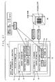
- FIG. 1 is a block diagram illustrating the structure of an onboard-type navigation apparatus according to a first embodiment of the present invention.
- the navigation apparatus comprises a control section 9, a storage section 4, an input section 5, an output section 6, a position detection section 7, and a communication section 8.
- control section 9 controls the other sections (i.e., the storage section 4, the input section 5, the output section 6, the position detection section 7, and the communication section 8) to realize various navigation functions, such as determining a current position of the-vehicle to thereby conduct a route search, or displaying images such as a map and/or guidance.
- the control section 9 includes a CPU 1, a RAM 2, and a ROM 3.
- the ROM 3 stores predetermined a program(s). The aforementioned various kinds of control are realized by the CPU 1 executing the program(s) in the ROM 3 while utilizing the RAM 2 as a working area.
- the storage section 4 which is implemented by using a storage medium such as a CD-ROM, a DVD, or a hard disk, stores various information, image data, and the like for conducting a route search and providing navigation guidance.
- FIG. 2 is a diagram illustrating a memory map of the storage section 4 shown in FIG. 1.
- the storage section 4 stores: information (3D map information 11) for drawing a plurality of 3D maps respectively corresponding to different areas; information (object information 12) for drawing a plurality of objects respectively corresponding to different navigation guidance signboards, road signs, and/or special structures; and image data 13.
- a "3D map” is a map which illustrates the topography of an area (which is defined as one of a number of grid-like subdivisions of a given terrain) in a three-dimensional manner, including structures within the area, e.g., roads, streets, bridges, and the like.
- a typical example of a navigation guidance signboard may be to a signboard which may be installed on a highway in front of a junction for providing guidance concerning lane switching, or a road guidance signboard which may be installed on non-highway roads in front of an intersection, etc.
- Typical examples of road signs include speed limit signs and wrong way signs.
- a "special structure" refers to a structure other than the structures which are already present on a 3D map. Typical examples of special structures include buildings accommodating business entities (e.g., bookstores or convenience stores), public facility buildings (e.g., city halls or post offices), parking lots, gas stations, and the like.
- An "object” is composed of a plurality of parts.
- a navigation guidance signboard is composed of a diagram (e.g., an arrow) and/or a text string (e.g., "TURN RIGHT") to provide navigation guidance for leading a user (vehicle) in a direction to proceed, and a signboard bearing such a diagram and/or a text string.
- a road sign is composed of. a diagram and/or a text string visually representing a traffic regulation (e.g., the well-known diagram representative of a wrong way, or encircled digits representative of a speed limit) as well as a signboard bearing such a diagram and/or a text string.
- a "building accommodating a bookstore” would include the structure (the building) itself as well as a signboard (e.g., "BOOKS”) visually indicating that a bookstore is accommodated in the building.
- the present navigation apparatus displays a navigation guidance signboard or the like described above as a superimposed image on a 3D map to lead a user (vehicle) in a direction to proceed, that is, a direction which is consistent with the optimum route.
- the present navigation apparatus has a function of informing the user of regulations such as speed limits, wrong ways, or the like found in the neighborhood of the current position by displaying (as superimposed images on a 3D map) objects corresponding to such road signs in the neighborhood of the current position or special structures (e.g., business entities or parking lots not originally included on the 3D map) in the neighborhood of the current position, and informing the user of the positions of special structures in the neighborhood of the current position as well as what those structures are (or what sort of business entities are accommodated in such structures).
- regulations such as speed limits, wrong ways, or the like found in the neighborhood of the current position by displaying (as superimposed images on a 3D map) objects corresponding to such road signs in the neighborhood of the current position or special structures (e.g., business entities or parking lots not originally included on the 3D map) in the neighborhood of the current position, and informing the user of the positions of special structures in the neighborhood of the current position as well as what those structures are (or what sort of business entities are accommodated in such
- the most important feature of the present navigation apparatus is that a transparency attribute is set for each one of the parts composing an object, where the transparency attribute is predetermined to be either opaque or non-opaque, depending on the significance level of the part.
- the diagram and/or text string constitutes a significant part, whereas the signboard itself constitutes a non-significant part. Accordingly, "non-opaque" is assigned as a predetermined transparency attribute for the signboard, whereas "opaque” is assigned as a predetermined transparency attribute for the diagram and/or text string.
- an opaque mage of the diagram and/or text string and a non-opaque image of the signboard are superimposed on the 3D map.
- the user can clearly recognize the diagram and/or text string as a visual representation of navigation guidance, and yet see through the non-opaque signboard to the portion of the 3D map underlying the signboard (i.e., the roads, streets, buildings, etc., lying ahead of the signboard).
- non-opaque is stored as a predetermined transparency'attribute for the building
- opaque is stored as a predetermined transparency attribute for the signboard.
- a state of being "non-opaque” includes a state of being transparent and a state of being translucent.
- Methods of displaying transparent objects include displaying objects as wire frames, among other methods.
- Methods of displaying translucent objects include shading or coloring objects which are displayed as wire frames, among other methods.
- a state of being “opaque” is not limited to a state of complete opaqueness (i.e., zero transparency).
- a state of being “transparent” is not limited to a state of complete transparentness (i.e., 100% transparency).
- a 95% transparency may be considered “transparent”, a 30% transparency “translucent”, and a 5% transparency "opaque”.
- a state of being “translucent” is simply defined by a lower level of transparency than that defining a state of being “transparent”
- a state of being “opaque” is simply defined by a lower level of transparency than that defining a state of being “translucent”.
- the input section 5 which may be implemented as a keyboard, a touch panel or the like, receives an instruction inputted by the user.
- the output section 6, which may be implemented as a display device, etc., outputs the 3D map and/or objects as graphical images.
- the position detection section 7, which is implemented as a GPS receiver, etc., detects the current position of the vehicle.
- the communication section 8, which is implemented as a mobile phone, etc., obtains information which may be necessary for the route search, e.g., traffic information or weather information, and/or latest information (e.g., business hours) concerning business entities, parking lots, and the like alongside the route, from a source external to the vehicle.
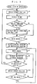
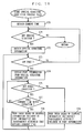
- FIG. 3 is a flowchart illustrating the operation of the present navigation apparatus (and in particular that of the control section 9).
- the control section 9 first obtains the current position of the vehicle via the position detection section 7 (step S1). Specifically, the position detection section 7 receives radiowaves from GPS satellites to calculate the current position therefrom, and passes the result of the calculation to the control section 9.
- control section 9 reads a 3D map of the neighborhood of the current position of the vehicle from the storage section 4, and outputs the 3D map via the output section 6 so as to be displayed on the display device (step S2).
- step S2 the 3D map displaying process of step S2 will be specifically described.
- FIG. 4 is a diagram illustrating (A) the structure of each unit of 3D map information 11 stored in the storage section 4 shown in FIG. 1, and (B) an exemplary image of a 3D map which is drawn based on that information.
- the 3D map information 11 stored in the storage section 4 includes position information 21 (i.e., information that can identify which 3D map corresponds to which area, expressed in terms of latitudes and longitudes, etc.), and drawing information 22 for drawing a 3D map of that area.
- position information 21 i.e., information that can identify which 3D map corresponds to which area, expressed in terms of latitudes and longitudes, etc.
- drawing information 22 for drawing a 3D map of that area.
- the control section 9 first refers to the position information 21 included in each unit of 3D map information 11 stored in the storage section 4 to select a unit of 3D map information 11 which corresponds to an area containing the vehicle. Then, the control section 9 performs a drawing process based on the drawing information 22 included in that 3D map information 11 while utilizing the image data 13 stored in the storage section 4, and outputs the resultant 3D map via the output section 6. Thus, a 3D map as shown in (B) of FIG. 4 is displayed on the display device.
- step S3 the control section 9 next determines whether or not to display a special structure. If the result of the determination is affirmative, the control section 9 displays the special structure (step S4), and proceeds to step S5. On the other hand, if the result of the determination is negative, the control section 9 proceeds directly to step S5. The details of a special structure displaying process of step S4 will be described later.
- control section 9 determines whether or not to conduct a route search (step S5). If the result of the determination is negative, the control section 9 returns to step S1.
- step S6 the control section 9 obtains the positions of a starting location and a destination location (step S6).
- the position of the starting location is the current position which has been obtained at step S1
- the position of the destination location is a position which is inputted by the user via the input section 5. Both positions may be expressed in terms of latitudes and longitudes, for example.
- control section 9 searches for an optimum route from the starting location to the destination location (step S7).
- This route search may be accomplished by well-known Dijkstra's algorithm, among other search methods.
- control section 9 displays a navigation guidance signboard which visually represents a direction for the vehicle to proceed as a superimposed image on the 3D map which is being displayed by the process of step S2 (step S8).
- step S8 a navigation guidance signboard displaying process of step S8 will be specifically described.
- FIG. 5 is a flowchart illustrating the details of step S8 (navigation guidance signboard displaying process) in FIG. 3.
- the control section 9 first obtains the current position of the vehicle via the position detection section 7 (step S21).
- the control section 9 generates navigation data describing a direction for the vehicle to proceed (step S22). Specifically, if the vehicle needs to make a right turn at the next intersection in order to proceed along the optimum route, navigation data indicating a right turn is generated.
- control section 9 outputs a navigation guidance signboard corresponding to the navigation data generated at step S22 via the output section 6 (step S23).
- a navigation guidance signboard indicating a direction for the vehicle to proceed is displayed as a superimposed image on the 3D map which is being displayed by the process of step S2.
- control returns to the flow of FIG. 3 to execute step S9 (the process of S9 and the subsequent steps will be described later).
- step S23 (navigation guidance signboard outputting process) of FIG. 5 will be specifically described.
- the navigation guidance signboard is a lane guidance signboard having a plurality of arrows respectively corresponding to a plurality of lanes, where only the arrow corresponding to the lane (direction) for the vehicle to take is displayed in a different color.
- the aforementioned "lane guidance signboard” is composed of two parts, namely, the signboard and the plurality of arrows respectively corresponding to the plurality of lanes (possible directions to proceed) indicated on the signboard.
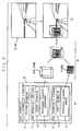
- FIG. 6 is a diagram illustrating (A) the structure of the navigation guidance signboard information stored in the storage section 4 shown in FIG. 1, (B) an exemplary image of a signboard which is drawn based on that information, and (C) an overall image of the signboard being superimposed on the 3D map.
- the navigation guidance signboard information stored in the storage section 4 includes: navigation direction information 31, i.e., information indicating directions (e.g., straight, right turn, or left turn) which the navigation guidance provided by a given signboard concerns; and part information 32, i.e., information concerning each of the parts composing the navigation guidance signboard part (note that the signboard itself is a part, whereas any arrow indicated thereon is another).
- navigation direction information 31 i.e., information indicating directions (e.g., straight, right turn, or left turn) which the navigation guidance provided by a given signboard concerns
- part information 32 i.e., information concerning each of the parts composing the navigation guidance signboard part (note that the signboard itself is a part, whereas any arrow indicated thereon is another).
- Each unit of part information 32 includes: drawing information 33 for drawing a part, where the information includes the shape, color, etc., of the part; and a transparency attribute 34 which indicates whether the part is to be displayed as an opaque image or a non-opaque image.
- FIG. 6 illustrates a lane guidance signboard having a plurality of arrows respectively expressing different lanes indicated on the signboard.
- the arrow corresponding to the rightmost lane is displayed in a different color from the other arrows to instruct the user to go down the rightmost lane corresponding to the colored arrow and then turn right.
- [opaque] is set as the transparency attribute 34 for the plurality of arrows, which are considered-as significant parts, whereas [translucent] is set as the transparency attribute 34 for the signboard, which is considered as a non-significant part.
- this lane guidance signboard will be displayed in such a manner that the arrows appear opaque whereas the signboard appears translucent, since the transparency attribute 34 of the arrows is set to [opaque] and the transparency attribute 34 of the signboard is set to [translucent].
- the transparency attribute 34 of the non-significant part signboard is set to [translucent] so that the signboard is displayed as a translucent image in this example, it is also applicable to set the transparency attribute 34 of the signboard to [transparent] so that the signboard will be displayed as a transparent image.
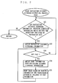
- FIG. 7 is a flowchart illustrating the details of step S23 (navigation guidance signboard outputting process) in FIG. 5.
- the control section 9 first determines whether or not any object information 12 including direction information which matches the direction indicated by the navigation data generated at step S22 is present in the storage section 4 (step S31). If the result of the determination is negative, the control returns to the flow of FIG. 3 to execute step S9.
- step S31 If the result- of the determination at step S31 is affirmative, the control section 9 obtains object information 12 [navigation guidance signboard] including direction information which matches the direction indicated by the navigation data from the storage section 4 (step S32). Then, it is determined whether or not the object information 12 includes any part information 32 (step S33). If the result of the determination is negative, the control returns to step S31.
- step S33 If the result of the determination at step S33 is affirmative, the control section 9 retrieves part information 32 from the object information 12 obtained at step S32 (step S34). Then, in accordance with the drawing information 33 and the transparency attribute 34 included in each unit of part information 32 retrieved, a drawing process is performed using the image data 13 stored in the storage section 4. The resultant navigation guidance signboard is outputted via the output section 6 (step S35). Thereafter, the control returns to step S33, and similar processes are repeated as described above.
- the transparency attribute 34 of the signboard is [translucent] and the transparency attribute 34 of the arrows is [opaque].
- a 3D map is being displayed on the display device by the process of step S2.
- the aforementioned navigation guidance signboard having opaque arrows on a translucent signboard, is superimposed. All of the arrows on the signboard shown in (C) of FIG. 6 (lower diagram) are opaque, and only the rightmost arrow has a different color than the others (for example, the rightmost arrow may be colored red, while the other arrows may be colored white). Based on the one arrow which is colored differently, the user will know that the user needs to go down the rightmost lane and turn right at the next intersection in order to proceed along the optimum route to the destination location.
- a main characteristic of the above navigation guidance signboard is that the arrows, which are considered significant because of indicating navigation guidance, are displayed as opaque images, whereas the non-significant signboard (other than the portions corresponding to the arrows) is displayed as a translucent image.
- the user will be able to see through to the roads, streets, buildings, etc., lying ahead of the signboard, and yet clearly recognize the arrows because they are not obscured by any underlying roads, streets, or buildings.
- conventional navigation apparatuses which provide navigation guidance by displaying a navigation guidance signboard so as to overlie a 3D map have the following problems. That is, if an entirely opaque navigation guidance signboard (containing opaque arrows) is displayed by such a conventional navigation apparatus, the signboard will be clearly visible, but the roads, streets, buildings, etc., lying ahead of the signboard will be concealed from view by the signboard. On the other hand, if an entirely translucent (or transparent) navigation guidance signboard (containing translucent or transparent arrows) is displayed by such a conventional navigation apparatus, the signboard itself appears obscure although the roads, streets, buildings, etc., lying ahead of the signboard will be visible through the signboard. In either case, it is difficult to drive a vehicle while relying on the navigation guidance signboard.
- the navigation apparatus displays a navigation guidance signboard as a superimposed image on a 3D map, such that only the arrows are opaque, and the signboard except for the portions corresponding to the arrows is translucent (or transparent). Therefore, arrows indicating navigation guidance can be recognized without fail, and yet it is possible to see through the signboard (except for the portions corresponding to the arrows) to the roads, streets, buildings, etc., lying ahead of the signboard. As a result, it is possible to know in advance what sort of driving operation is required in order to follow along the navigation guidance, whereby driving in accordance with the navigation guidance can be facilitated.
- control section 9 next determines whether or not the destination location has been reached (step S9). If the result of the determination is affirmative, the control returns to step S1.
- step S9 determines whether the current position of the vehicle is off the route or not (step S11). If the result of the determination is negative, the control returns to step S8 and continues to provide navigation guidance along the currently optimum route.
- step S11 If the result of the determination at step S11 is affirmative, the control section 9 returns to step S7 to conduct another route search. Thereafter, navigation guidance is provided along the optimum route which has been newly looked up.
- step S4 in FIG. 3 Next, the details of the special structure displaying process of step S4 in FIG. 3 will be described.
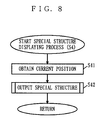
- FIG. 8 is a flowchart illustrating the details of step S4 (special structure displaying process) in FIG. 3.
- the control section 9 first obtains the current position of the vehicle via the position detection section 7 (step S41).
- the control section 9 outputs a special structure(s) in the neighborhood of the current position obtained at step S41 via the output section 6 (step S42).
- the special structure(s) is displayed as a superimposed image on the 3D map which is being displayed by the process of step S2.
- the control returns to the flow of FIG. 3 to execute step S5 (the ensuing processes have already been described above).
- step S42 in FIG. 8 The following description is directed to an exemplary case where the special structure is a "building accommodating a bookstore".
- the "building accommodating a bookstore” is composed of two parts, namely, the building itself and a signboard shown on the building to indicate that the building accommodates a bookstore.
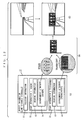
- FIG. 9 is a diagram illustrating (A) the structure of the object information 12 [building accommodating a bookstore] stored in the storage section 4 shown in FIG. 1, (B) an exemplary image of a building accommodating a bookstore which is drawn based on that information, and (C) an overall image of the building accommodating a bookstore being superimposed on the 3D map.
- the object information 12 [building accommodating a bookstore] stored in the storage section 4 includes: position information 41, i.e., information representing the position of the object; and part information 42, i.e., information concerning each of the parts composing the object (note that the building itself is a part, whereas the signboard shown on the building is another).
- Each unit of part information 42 includes: drawing information 43 for drawing a part, where the information includes the shape, color, etc., of the part; and a transparency attribute 44 which indicates whether the part is to be displayed as an opaque image or a non-opaque image (which in the present example is assumed to be a transparent wire frame image).
- [opaque] is set as the transparency attribute 44 for the signboard, which is considered as a significant part
- [transparent] is set as the transparency attribute 44 for the building itself, which is considered as a non-significant part.
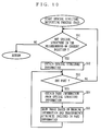
- FIG. 10 is a flowchart illustrating the details of step S42 (special structure outputting process) in FIG. 8.
- the control section 9 first determines whether or not any object information 12 concerning a special structure(s) located in the neighborhood of the current position obtained at step S41 is present in the storage section 4 (step S51). If the result of the determination is negative, the control returns to the flow of FIG. 3 to execute step S5.
- step S51 If the result of the determination at step S51 is affirmative, the control section 9 obtains object information 12 [building accommodating a bookstore] whose position information 41 indicates a position within a predetermined neighborhood region of the current position from the storage section 4 (step S52). Then, the control section 9 determines whether the object information 12 includes part information 42 or not (step S53). If the result of the determination is negative, the control returns to step S51.
- control section 9 retrieves part information 42 from the object information 12 which was obtained at step S52 (step S54). In accordance with the drawing information 43 and the transparency attribute 44 included in each retrieved unit of part information 42, the control section 9 performs a drawing process using the image data 13 stored in the storage section 4, and outputs a special structure thus obtained via the output section 6 (step S55). Thereafter, the control returns to step S53, and similar processes are repeated as described above.
- the transparency attribute 44 of the building is [transparent] and the transparency attribute 44 of the signboard is [opaque].
- a 3D map is being displayed on the display device by the process of step S2.
- the aforementioned special structure i.e., a "building accommodating a bookstore” having an opaque signboard shown on a transparent wire frame building, is superimposed.
- the text string "BOOKS” is indicated on the signboard shown in (C) of FIG. 9 (lower diagram). Based on this signboard, the user will know the position of the bookstore on the 3D map.
- a main characteristic of the above special structure e.g., a "building accommodating a bookstore” is that the signboard, which is considered significant because of indicating that the building accommodates a bookstore, is displayed as an opaque image, whereas the non-significant building itself (other than the portion corresponding to the signboard) is displayed as a transparent image.
- a special structure e.g., a "building accommodating a bookstore”
- the user will be able to see through to the roads, streets, or other buildings lying ahead of the building, and yet clearly recognize the signboard which is not obscured by any underlying roads, streets, or buildings.
- the conventional cases of displaying a special structure so as to overlie a 3D map have the following problems. That is, if an entirely opaque special structure (containing an opaque signboard) is displayed, the structure will be clearly visible, but the roads, streets, buildings, etc., lying ahead of the structure will be concealed from view by the structure. On the other hand, if an entirely translucent (or transparent) special structure (containing a translucent or transparent signboard) is displayed, the signboard appears obscure although the roads, streets, buildings, etc., lying ahead of the structure will be visible through the structure. As a result, it becomes difficult to know what the structure contains.
- the navigation apparatus displays a special structure as a superimposed image on a 3D map, such that only the signboard is opaque, and the structure itself is transparent (or translucent) . Therefore, it is possible to clearly recognize the signboard, which is essential for knowing what the structure is (i.e., what sort of business entity is accommodated therein) , and yet it is possible to see through the structure (except for the portion corresponding to the signboard) to the roads, streets, or other buildings, etc., so that it is possible to grasp the position of the special structure on the 3D map.
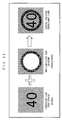
- FIG. 11 An exemplary image of a speed limit sign is shown in FIG. 11, and an exemplary image of a road guidance signboard is shown in FIG. 12.
- a text string "40” which is a visual representation of a speed limit, constitutes a significant part, whereas a diagram (circular frame) around the text string "40" constitutes a non-significant part. Accordingly, the text string "40" is displayed as an opaque image, whereas the circular frame around it is displayed as a translucent image (or alternatively, the entire signboard including the circular frame but except for the text string "40” may be displayed as a translucent image).
- text strings " ⁇ ” and the like which are visual representations of distant destinations, constitute significant parts, whereas the signboard itself constitutes a non-significant part. As a result, the text strings " ⁇ ” and the like are displayed as opaque images, whereas the signboard itself is displayed as a translucent image.
- lane guidance signboards may be displayed as mere objects similar to special structures, without functioning as navigation guidance signboards.
- Such a lane guidance signboard displayed as a special structure will typically include arrows all of which are displayed in the same color (e.g., white), as opposed to the aforementioned lane guidance signboard (see FIG. 6) functioning as a navigation guidance signboard, in which only the arrow corresponding to a direction to proceed is displayed in a different color among a plurality of arrows respectively corresponding to various lanes.
- FIG. 13 shows a lane guidance signboard being displayed as a mere object superimposed on a 3D map, where (A) is the structure of information (object information 12 [lane guidance signboard]) pertaining to this signboard; (B) is an exemplary image of the signboard; and (C) is an overall image of the signboard being superimposed on the 3D map.
- non-opaque is set as the predetermined transparency attribute 34 for the signboard which constitutes a non-significant part
- opaque is set as the predetermined transparency attribute 34 for a diagram and/or a text string indicative of navigation guidance, which constitutes a significant part.
- the user can know in advance what sort of driving operation is required in order to follow along the navigation guidance, whereby driving in accordance with the navigation guidance can be facilitated.
- non-opaque is set as the predetermined transparency attribute 44 for the structure itself, which constitutes a non-significant part
- opaque is set as the predetermined transparency attribute 44 for the signboard shown on the structure, which is a significant part indicative of what the structure is (or what sort of business entity is accommodated in the structure).
- a user can visually recognize the signboard indicative of what the structure is (or what sort of business entity is accommodated therein) without fail, and yet see through the structure itself (except for the portion corresponding to the signboard) to the roads, streets, buildings, etc., which are present on the 3D map.
- non-opaque is set as the predetermined transparency attribute 54 for the signboard, which constitutes a non-significant part
- opaque is set as the predetermined transparency attribute 54 for the diagram and/or text string, which is a significant part indicative of traffic regulations or road guidance.
- the user can visually recognize the diagram and/or text string indicative of traffic regulations (e.g., speed limits or wrong ways) or road guidance without fail, and yet easily see through the signboard (except for the portion corresponding to the diagram and/or text string) to the roads, streets, buildings, etc., which are present on the 3D map.
- traffic regulations e.g., speed limits or wrong ways
- road guidance e.g., road guidance
- the signboard except for the portion corresponding to the diagram and/or text string
- step S4 in FIG. 3 illustrates an example where a special structure in the neighborhood of the current position is displayed, it would also be applicable to wait for a destination location to be inputted, and display a special structure which is in the neighborhood of the destination location.
- the user may select a desired business entity, e.g., by designating the name, address, telephone number, or the like of a business entity, and a special structure accommodating the selected business entity may be displayed.
- a desired business entity e.g., by designating the name, address, telephone number, or the like of a business entity
- a special structure accommodating the selected business entity may be displayed.
- a "bookstore" for example, a building accommodating the bookstore, with an opaque signboard shown on a transparent building, is displayed as a superimposed image on a 3D map.
- the special structure selected as the destination location may be displayed.
- a method for designating a destination location for a route search a method is known in which a user inputs the telephone number or the address of the building of a business entity. Responsive to the selection of a special structure as a destination location based on the inputting of a telephone number or an address, a special structure selected as the destination location may be displayed. For example, if the user inputs the telephone number of a "bookstore" as a destination location to head for, then a building accommodating the bookstore, with an opaque signboard shown on a transparent building, is displayed as a superimposed image on a 3D map.
- a special structure to be superimposed on a 3D map can be selected based on various criteria. Irrespective of which special structure is to be displayed, a signboard will be displayed as an opaque image and the structure itself will be displayed as a non-opaque image through a processing procedure similar to that described above.
- the transparency attribute of each of the parts composing an object to be superimposed on a 3D map is predetermined to be opaque or non-opaque depending on whether that part is significant or non-significant, such that the transparency attribute never changes.
- the transparency attribute of each part is predetermined to be opaque or non-opaque depending on whether that part is significant or non-significant in a manner similar to the first embodiment.
- the transparency attribute of a part is dynamically changed from opaque to non-opaque as the once-significant part becomes non-significant under a predetermined condition, according to the second embodiment.
- the configuration of the navigation apparatus according to the second embodiment of the present invention is similar to that of the navigation apparatus according to the first embodiment as shown in FIG. 1. Except for the following points, the operations of the respective sections shown in FIG. 1 are also similar to the operations under the first embodiment. Therefore, in the present embodiment, only the differences from the first embodiment will be described, while omitting the detailed descriptions of any operations which are similar to that according to the first embodiment.
- the storage section 4 shown in FIG. 1 has a memory map similar to that according to the first embodiment, which is shown in FIG. 2.
- the 3D map information 11 shown in FIG. 2 has a structure similar to that according to the first embodiment, which is shown in FIG. 4.
- the object information 12 shown in FIG. 2 includes direction information (see 31 in FIG. 6(A)) or position information (see 41 in FIG. 9(A) or 51 in FIG. 13(A)), and a plurality of units of part information (see 32 in FIG. 6(A), 42 in FIG. 9(A), or 52 in FIG. 13(A)).
- each unit of part information has a different structure from that according to the first embodiment. The differences between the structure of the part information according to the first embodiment and that according to the present embodiment can be seen from FIGS. 14A and 14B.
- FIG. 14A shows the structure of part information according to the first embodiment.
- FIG. 14B shows the structure of the part information according to the present embodiment.
- each unit of part information 61 includes drawing information 62 and a predetermined transparency attribute 63.
- each unit of part information 64 includes drawing information 65, a predetermined transparency attribute (default transparency attribute 66) , and a transparency attribute 67 which becomes valid only under a predetermined condition.
- step S2 in FIG. 3 The fundamental operation of the navigation apparatus according to the present embodiment is similar to that described in the first embodiment, which is illustrated in FIG. 3.
- the 3D map which is displayed at step S2 in FIG. 3 is similar to its counterpart in the first embodiment, which is shown in FIG. 4.
- step S8 in FIG. 3 The details of step S8 in FIG. 3 are as in the first embodiment, which are shown in FIG. 5, except for step S23 (navigation guidance signboard outputting process). Therefore, the details of step S23 (navigation guidance signboard outputting process) in FIG. 5 according to the second embodiment will be described below.
- the following example illustrates the case where the navigation guidance signboard is a "lane guidance signboard having a plurality of arrows respectively corresponding to a plurality of lanes, where only the arrow corresponding to the lane (direction) to take is displayed as an opaque image and the other arrows as well as the signboard itself are displayed as a translucent image".
- the "lane guidance signboard” is composed of a signboard and a plurality of arrows respectively corresponding to a plurality of lanes, the arrows being shown on the signboard. Whereas the entire group of arrows is regarded as one part in the first embodiment, the present embodiment regards each arrow as one part.
- the signboard itself constitutes a part; a right turn arrow constitutes another; a straight arrow constitutes still another; and a left turn arrow constitutes yet another.
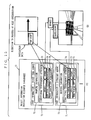
- FIG. 15 is a diagram illustrating (A) the structure of the object information 12 [navigation guidance signboard] stored in the storage section 4 shown in FIG. 1, and (B) an overall image of a signboard, which is drawn based on that information, being superimposed on the 3D map.
- object information 12 stored in the storage section 4 includes information (part information 71) concerning each of the parts composing the navigation guidance signboard (where the signboard itself constitutes a part; a right turn arrow shown thereon constitutes another; and a straight arrow shown thereon constitutes still another). Note, however, that only two units of part information 71, one for the right turn arrow and one for the straight arrow are shown in (A) of FIG. 15 for conciseness.
- Each unit of part information 71 includes: drawing information 72 for drawing a part, where the information includes the shape, color, etc., of the part; a default transparency attribute 73 which indicates whether the part is to be displayed as an opaque image or a non-opaque image; one or more conditions; and one or more transparency attribute 74 associated with the respective conditions.
- the default transparency attribute 73 is [opaque]; the transparency attribute 74 which becomes valid only under the condition [when going straight] is [translucent]; the transparency attribute 74 which becomes valid only under the condition [when turning left] is also [translucent].
- the default transparency attribute 73 is [opaque]; the transparency attribute 74 which becomes valid only under the condition [when turning right] is [translucent]; and the transparency attribute 74 which becomes valid only under the condition [when turning left] is also [translucent].
- the signboard itself includes drawing information and a default transparency attribute [translucent], but does not include a conditional transparency attribute.
- [translucent] as the transparency attribute which is set for the non-significant signboard so that the signboard is displayed as a translucent image
- [transparent] may instead be set as the transparency attribute for the signboard, so that the signboard is displayed as a transparent image.
- FIG. 16 is a flowchart illustrating the details of step S23 (navigation guidance signboard outputting process) in FIG. 5.
- the control section 9 first determines whether or not object information 12 [navigation guidance signboard] is present in the storage section 4 (step S61). If the result of the determination is negative, the control returns to the flow of FIG. 3 to execute step S9.
- step S61 If the result of the determination at step S61 is affirmative, the control section 9 obtains object information 12 [navigation guidance signboard] from the storage section 4 (step S62). Next, it is determined whether or not the object information 12 includes part information 71 (step S63). If the result of the determination is negative, the control returns to step S61.
- control section 9 retrieves part information 71 from the object information 12 obtained at step S62 (step S64), and determines whether or not a condition is set within the part information 71 (step S65). If the result of the determination is negative, the control section 9 performs a drawing process in accordance with the drawing information 72 and the default transparency attribute 73 included in the part information 71 retrieved at step S64, using the image data 13 stored in the storage section 4. The control section 9 outputs the resultant navigation guidance signboard via the output section 6 (step S66). Thereafter, the control returns to step S63, and similar processes are repeated for the other parts as described above.
- step S65 If the result of the determination at step S65 is affirmative, it is determined whether or not a condition which is set within the part information 71 retrieved at step S64 matches a direction which is indicated by the navigation data generated at step S22 (step S67). If the result of the determination is negative, the control returns to step S65 to determine whether there is any other condition or not. If there are no other conditions, the control proceeds to step S66 to perform drawing based on the default transparency attribute 73.
- control section 9 performs a drawing process in accordance with the drawing information 72 included in the part information 71 retrieved at step S64 and a transparency attribute 74 which corresponds to the direction indicated by the navigation data (i.e., the transparency attribute 74 which becomes valid only under that condition), using the image data 13 stored in the storage section 4.
- the control section 9 outputs the resultant navigation guidance signboard via the output section 6 (step S68). Thereafter, the control returns to step S63, and similar processes are repeated for the other parts as described above.
- the default transparency attribute 73 is [opaque]; the transparency attribute 74 which becomes valid only under the condition [when turning right] is [translucent]; and the transparency attribute 74 which becomes valid only under the condition [when turning left] is also [translucent].
- the right turn arrow is drawn based on the default transparency attribute [opaque] because no condition that matches "TURN RIGHT” is set for the right turn arrow.
- the straight arrow is drawn based on the transparency attribute [translucent] when turning right because a condition that matches "TURN RIGHT” is set for the straight arrow.
- the signboard itself is drawn based on the default transparency attribute [opaque].
- a navigation guidance signboard is outputted at step S23 such that only the right turn arrow which matches the direction indicated by the navigation data (i.e., "TURN RIGHT” in this case) appears opaque, with the straight and other arrows as well as the signboard itself appearing translucent.
- a 3D map is being displayed on the display device by the process of step S2.
- the aforementioned navigation guidance signboard where only the right turn arrow appears opaque and the other arrows and the signboard itself appear translucent, is superimposed. Based on the one arrow which appears opaque, the user will know that the user needs to go down the rightmost lane and turn right at the next intersection in order to proceed along the optimum route to the destination location.
- a main characteristic of the above navigation guidance signboard is that only the straight arrow, which is considered significant because of indicating navigation guidance, is displayed as an opaque image, whereas the non-significant parts, i.e., the straight and other arrows as well as the signboard are displayed as translucent images.
- the user will be able to see through to the roads, streets, buildings, etc., lying ahead of the signboard, and yet clearly recognize the straight arrow because it is not obscured by any underlying roads, streets, or buildings.
- a navigation guidance signboard which is displayed according to the first embodiment is such that all of the arrows thereon appear opaque except for one arrow indicating a direction to proceed, which is displayed in a different color from the other arrows.
- a navigation guidance signboard according to the present embodiment is displayed in such a manner that only the arrow indicating a direction to proceed appears opaque, with all the other arrows being translucent (or transparent) .
- the arrows which are not essential to the navigation guidance are displayed as translucent images, it is possible to see through a broader area of the signboard than under the first embodiment and it becomes even easier for the user to drive a vehicle in accordance with the navigation guidance.
- step 23 (navigation guidance signboard outputting process) in FIG. 5 has been described.
- step S4 are as in the first embodiment, which are shown in FIG. 8, except for step S42 (special structure outputting process). Therefore, the details of step S42 (special structure outputting process) in FIG. 8 will be described below.
- the following example illustrates the case where the special structure is a "building accommodating a bookstore".
- the "building accommodating a bookstore” is composed of two parts, i.e., the building itself and a signboard shown on the building for indicating that a bookstore is accommodated in the building.
- FIG. 17 is a diagram illustrating (A) the structure of object information 12 [building accommodating a bookstore] stored in the storage section 4 shown in FIG. 1, and (B) an exemplary image of a building accommodating a bookstore which is drawn based on that information.
- the object information 12 [building accommodating a bookstore] stored in the storage section 4 includes information (position information 81) indicating the position of the object, and information (part information 82) concerning each of the parts composing the object (where the building itself constitutes a part, and the signboard shown on the building constitutes another)
- Each unit of part information 82 includes: drawing information 83 for drawing a part, where the information includes the shape, color, etc., of the part; and a default transparency attribute 84 which indicates whether the part is to be displayed as an opaque image or a non-opaque image (which in the present example is assumed to be a transparent wire frame image).
- [opaque] is set as the default transparency attribute 84 for the signboard, which constitutes a significant part
- [transparent] is set as the default transparency attribute 84 for the non-significant building itself.
- [translucent] is set as a transparency attribute 85 which becomes valid only under the condition [closed (i.e., the business entity is not operating)], in addition to the default transparency attribute 84.
- the "building accommodating a bookstore” will be displayed in such a manner that the building itself appears as a transparent and three-dimensional wire frame, etc., whereas the signboard (bearing a text string "BOOKS” in this example) usually appears opaque but translucent when the bookstore is closed.
- FIG. 18 is a flowchart illustrating the details of step S42 (special structure outputting process) in FIG. 8.
- the control section 9 first obtains the current time (step S70), and then determines whether or not object information 12 [building accommodating a bookstore] is present in the storage section 4 (step S71). If the result of the determination is negative, the control returns to the flow of FIG. 3 to execute step S9.
- step S71 If the result of the determination at step S71 is affirmative, the control section 9 obtains object information 12 from the storage section 4 (step S72). Then, it is determined whether or not the object information 12 includes part information 82 (step S73). If the result of the determination is negative, the control returns to step S71.
- control section 9 retrieves part information 82 from the object information 12 obtained at step S72 (step S74), and determine whether or not a condition is set within the part information 82 (step S75). If the result of the determination is negative, the control section 9 performs a drawing process in accordance with the drawing information 83 and the default transparency attribute 84 included in the part information 82 retrieved at step S74, using the image data 13 stored in the storage section 4. The control section 9 outputs the resultant special structure via the output section 6 (step S76). Thereafter, the control returns to step S73, and similar processes are repeated for the other parts as described above.
- step S75 If the result of the determination at step S75 is affirmative, it is determined whether a condition which is set within the part information 82 retrieved at step S74 matches the current time as obtained at step S60 (step S77). If the result of the determination is negative, the control returns to step S75 to determine whether there is any other condition or not. If there are no other conditions, the control proceeds to step S76 to perform drawing based on the default transparency attribute 84.
- step S77 If the result of the determination at step S77 is affirmative (i.e., the bookstore is currently closed), the control section 9 performs a drawing process in accordance with the drawing information 83 included in the part information 82 retrieved at step S74 and the transparency attribute 85 corresponding to a condition that matches the current time (i.e., the transparency attribute 85 which becomes valid only under that condition) , using the image data 13 stored in the storage section 4.
- the control section 9 outputs the resultant special structure via the output section 6 (step S78). Thereafter, the control returns to step S73, and similar processes are repeated for the other parts as described above.
- the default transparency attribute 84 is [transparent], and no condition is set.
- the default transparency attribute 84 is [opaque], and a condition [closed] is set, and the transparency attribute 85 which becomes valid only under the condition [closed] is [translucent].
- the signboard will be drawn based on the transparency attribute [translucent] which becomes valid only under the condition [closed] because the current time matches the condition [closed].
- the building for which no particular condition is set, is drawn based on the default transparency attribute [transparent].
- the signboard will also be drawn based on its default transparency attribute [opaque] because no condition is set that matches such time.
- a special structure [building accommodating a bookstore] is outputted at step S42 such that the signboard appears translucent when the current time matches the condition [closed] (i.e., when the bookstore is currently closed) and otherwise (i.e., when the bookstore is operating) opaque, with the building itself always appearing transparent.
- a 3D map is being displayed on the display device by the process of step S2.
- the aforementioned special structure where the building always appears transparent but the signboard usually (i.e., during business hours) appears opaque but translucent when the bookstore is closed, is superimposed.
- a signboard which is considered significant because of indicating that a bookstore is accommodated in the building always appears opaque, and the non-significant building itself (except for the portion corresponding to the signboard) always appears transparent.
- the present embodiment is similar to the first embodiment in that the building itself always appears transparent, but differs from the first embodiment in that the signboard appears translucent, rather than opaque, when the bookstore is closed. The rationale behind this is that the signboard is significant only while the business entity is operating but becomes non-significant when the business entity is closed.
- the user will only grasp the positions (on the 3D map) of special structures accommodating business entities which are operating. Since the signboard of any closed business entity is displayed as a translucent image, the portions which would be concealed under the signboard according to the first embodiment will become visible according to the second embodiment. As a result, the positions (on the 3D map) of special structures accommodating business entities which are operating can be grasped with an increased certainty.
- the present embodiment illustrates a building accommodating a bookstore as a special structure to be superimposed on a 3D map
- the same principle also applies to the case of displaying a road sign such as a speed limit sign or a wrong way sign, or a road guidance signboard.
- some wrong way regulations or no-parking regulations may be lifted during a specific time zone such as night hours or on Sundays.
- Such signs may be usually displayed as opaque images but can be switched to translucent images during the time zone when the corresponding regulations are lifted.
- a lane guidance signboard with a plurality of arrows is displayed in such a manner that only the arrow indicating a direction to proceed appears opaque, with all the other arrows being non-opaque.
- the user can clearly recognize only the arrow indicating navigation guidance, and yet see through the signboard (except for the portion corresponding to the arrow indicating the direction to proceed) to the 3D map.
- a lane guidance signboard (as a navigation guidance signboard) is displayed in such a manner that all of the arrows are opaque and only the arrow indicating the direction to proceed is displayed in a different color. Since it is possible to see a broader area of the 3D map through the signboard (except for the portion corresponding to the opaque arrow) than under the first embodiment, the roads, streets, buildings, etc., which are already present on the 3D map can be viewed even better. As a result, it becomes even easier for the user to drive a vehicle in accordance with the navigation guidance.
- a signboard which is usually displayed as an opaque image can be displayed as a non-opaque image during a predetermined time zone.
- a special structure which is a "building accommodating a bookstore" is displayed in such a manner that the building always appears non-opaque, whereas the signboard always appears opaque.
- the present embodiment is similar to the first embodiment in that the building itself always appears non-opaque, but differs from the first embodiment in that the signboard appears non-opaque, rather than opaque, when the current time falls in a time zone during which the bookstore is closed.
- more parts are displayed as non-opaque images, and a broader range of the 3D map can be seen through the non-opaque parts than in the first embodiment, so that the roads, streets, buildings, etc., which are already present on the 3D map can be viewed even better.
- a diagram and/or a text string which is usually displayed as opaque images can be displayed as non-opaque images during a predetermined time zone.
- a diagram and/or a text string is always displayed as non-opaque images, and the signboard is always displayed as an opaque image.
- the present embodiment is similar to the first embodiment in that the signboard always appears non-opaque, but differs from the first embodiment in that the diagram and/or text string is displayed as a non-opaque image, rather than an opaque image, when the current time falls in a time zone during which a traffic regulation represented by the diagram and/or text string is lifted.
Abstract
Description
Claims (16)
- A three-dimensional map and object displaying apparatus for displaying an object for visually conveying predetermined information to a user as a superimposed image on a three-dimensional map,
wherein the object includes a plurality of parts, the plurality of parts comprising a significant part and a non-significant part,
wherein the three-dimensional map and object displaying apparatus comprises:storage means (4) for storing drawing information and a predetermined transparency attribute for each part, the transparency attribute designating "opaque" or "non-opaque" in relation to a significance level of the part;map displaying means (6, 9, S2) for displaying the three-dimensional map; andobject displaying means (6, 9, S4, S8) for performing a drawing process based on the drawing information and the transparency attribute for each part stored in the storage means, thereby displaying an object as a superimposed image on the three-dimensional map being displayed by the map displaying means, such that the significant part appears as an opaque image and the non-significant part appears as a non-opaque image. - The three-dimensional map and object displaying apparatus according to claim 1,
wherein, for the significant part, the storage means stores: the predetermined transparency attribute designating "opaque", a predetermined condition, and a conditional transparency attribute designating "non-opaque" which becomes valid only under the predetermined condition, and
wherein the object displaying means determines (S67, S77) whether or not the significant part satisfies the condition, and displays the significant part as a non-opaque image if a result of the determination is affirmative. - The three-dimensional map and object displaying apparatus according to claim 1,
wherein the object is a navigation guidance signboard comprising a signboard and a diagram and/or a text string shown on the signboard for visually representing navigation guidance, such that the diagram and/or text string corresponds to the significant part and the signboard corresponds to the non-significant part,
wherein the storage means stores "non-opaque" as the predetermined transparency attribute for the signboard, and "opaque" as the predetermined transparency attribute for the diagram and/or text string, and
wherein the object displaying means displays the diagram and/or text string as an opaque image, and the signboard as a non-opaque image. - The three-dimensional map and object displaying apparatus according to claim 1,
wherein, the object is a lane guidance signboard comprising a signboard and a plurality of arrows shown on the signboard for representing respectively different lanes, such that the plurality of arrows respectively correspond to a plurality of said significant parts and the signboard corresponds to the non-significant part,
wherein the storage means stores "non-opaque" as the predetermined transparency attribute for the signboard, and "opaque" as the predetermined transparency attribute for each arrow, and
wherein the object displaying means displays each arrow as an opaque image, and the signboard as a non-opaque image. - The three-dimensional map and object displaying apparatus according to claim 1,
wherein the object comprises a special structure and a signboard accompanying the structure for visually representing an attribute of the structure, such that the signboard corresponds to the significant part and the special structure corresponds to the non-significant part,
wherein the storage means stores,
"non-opaque" as the predetermined transparency attribute for the special structure,
"opaque" as the predetermined transparency attribute for the signboard, and
wherein the object displaying means displays the signboard as an opaque image, and the special structure as a non-opaque image. - The three-dimensional map and object displaying apparatus according to claim 5, further comprising selection means (5) for selecting one of a plurality of said special structures,
wherein, for the signboard, the storage means stores: the predetermined transparency attribute designating "opaque" and a conditional transparency attribute designating "non-opaque" which becomes valid only when the special structure is unselected, and
wherein the object displaying means displays the signboard accompanying any said special structure that is selected by the selection means as an opaque image, and the signboard accompanying any said special structure that is unselected as an non-opaque image. - The three-dimensional map and object displaying apparatus according to claim 5,
wherein, for the signboard, the storage means stores: the predetermined transparency attribute designating "opaque", a predetermined time zone, and a conditional transparency attribute designating "non-opaque" which becomes valid only during the time zone, and
wherein the object displaying means determines (S77) whether or not the current time falls in the time zone, and displays the signboard as a non-opaque image if a result of the determination is affirmative. - The three-dimensional map and object displaying apparatus according to claim 1,
wherein the object is a road sign comprising a signboard and a diagram and/or a text string shown on the signboard for visually representing a traffic regulation, such that the diagram and/or text string corresponds to the significant part and the signboard corresponds to the non-significant part,
wherein the storage means stores:wherein the object displaying means displays the signboard as a non-opaque image, and the diagram and/or text string as an opaque image."non-opaque" as the predetermined transparency attribute for the signboard,"opaque" as the predetermined transparency attribute for the diagram and/or text string, and - The three-dimensional map and object displaying apparatus according to claim 8,
wherein, for the diagram and/or text string, the storage means stores: the predetermined transparency attribute designating "opaque", a predetermined time zone, and a conditional transparency attribute designating "non-opaque" which becomes valid only during the time zone, and
wherein the object displaying means determines whether or not the current time falls in the time zone, and displays the diagram and/or text string as a non-opaque image if a result of the determination is affirmative. - A three-dimensional map and object displaying method for displaying an object for visually conveying predetermined information to a user as a superimposed image on a three-dimensional map,
wherein the object includes a plurality of parts, the plurality of parts comprising a significant part and a non-significant part,
wherein the three-dimensional map and object displaying method comprises:a storage step of storing drawing information and a predetermined transparency attribute for each part, the transparency attribute designating "opaque" or "non-opaque" in relation to a significance level of the part;a map displaying step (S2) of displaying the three-dimensional map; andan object displaying step (S4, S8) of performing a drawing process based on the drawing information and the transparency attribute for each part stored in the storage step, thereby displaying an object as a superimposed image on the three-dimensional map being displayed by the map displaying step, such that the significant part appears as an opaque image and the non-significant part appears as a non-opaque image. - A three-dimensional map and object displaying program executed by a computer comprised in an apparatus for displaying an object for visually conveying predetermined information to a user as a superimposed image on a three-dimensional map,
wherein the object includes a plurality of parts, the plurality of parts comprising a significant part and a non-significant part,
wherein the three-dimensional map and object displaying program comprises:a storage step of storing drawing information and a predetermined transparency attribute for each part, the transparency attribute designating "opaque" or "non-opaque" in relation to a significance level of the part;a map displaying step (S2) of displaying the three-dimensional map; andan object displaying step (S4, S8) of performing a drawing process based on the drawing information and the transparency attribute for each part stored in the storage step, thereby displaying an object as a superimposed image on the three-dimensional map being displayed by the map displaying step, such that the significant part appears as an opaque image and the non-significant part appears as a non-opaque image. - A three-dimensional navigation apparatus for providing navigation by displaying a navigation guidance signboard as a superimposed image on a three-dimensional map,
wherein the navigation guidance signboard comprises a signboard and a diagram and/or a text string shown on the signboard for visually representing navigation guidance,
wherein the three-dimensional navigation apparatus comprises:storage means for storing: a predetermined transparency attribute designating "non-opaque" and drawing information for the signboard; and a predetermined transparency attribute designating "opaque" and drawing information for the diagram and/or text string;map displaying means (6, 9, S2) for displaying the three-dimensional map; andnavigation guidance signboard displaying means (6, 9, S8) for performing a drawing process based on the drawing information and the transparency attribute stored in the storage means, thereby displaying a navigation guidance signboard as a superimposed image on the three-dimensional map being displayed by the map displaying means, such that the diagram and/or text string appears as an opaque image and the signboard appears as a non-opaque image. - The three-dimensional navigation apparatus according to claim 12,
wherein the diagram and/or text string comprises a plurality of arrows visually representing respectively different lanes,
wherein the three-dimensional navigation apparatus further comprises search means (7, 9) for searching for an optimum route based on a current position of a vehicle, determining a direction for the vehicle to proceed, and informing the navigation guidance signboard displaying means of the direction,
wherein, for each arrow, the storage means stores: the predetermined transparency attribute designating "opaque", a direction represented by the arrow, and a conditional transparency attribute designating "non-opaque" which becomes valid only when the direction for the vehicle to proceed is inconsistent with the direction represented by the arrow, and
wherein, for each arrow, the navigation guidance signboard displaying means determines whether or not the direction for the vehicle to proceed is inconsistent with the direction represented by the arrow, and displays any said arrow for which a result of the determination is negative as an opaque image, and any said arrow for which a result of the determination is affirmative as a non-opaque image. - The three-dimensional navigation apparatus according to claim 12, further comprising selection means (5) for selecting one of a plurality of said special structures as a destination location,
wherein, for the signboard, the storage means stores: the predetermined transparency attribute designating "opaque" and a conditional transparency attribute designating "non-opaque" which becomes valid only when the special structure is unselected, and
wherein the object displaying means displays the signboard accompanying any said special structure that is selected by the selection means to be the destination location as a non-opaque image, and the signboard accompanying any said special structure that is unselected as a non-opaque image. - A three-dimensional navigation method for providing navigation by displaying a navigation guidance signboard as a superimposed image on a three-dimensional map,
wherein the navigation guidance signboard comprises a signboard and a diagram and/or a text string shown on the signboard for visually representing navigation guidance,
wherein the three-dimensional navigation method comprises:a storage step of storing: a predetermined transparency attribute designating "non-opaque" and drawing information for the signboard; and a predetermined transparency attribute designating "opaque" and drawing information for the diagram and/or text string;a map displaying step (S2) of displaying the three-dimensional map; anda navigation guidance signboard displaying step (S8) of performing a drawing process based on the drawing information and the transparency attribute stored in the storage step, thereby displaying a navigation guidance signboard as a superimposed image on the three-dimensional map being displayed by the map displaying step, such that the diagram and/or text string appears as an opaque image and the signboard appears as a non-opaque image. - A three-dimensional navigation program executed by a computer comprised in an apparatus for providing navigation by displaying a navigation guidance signboard as a superimposed image on a three-dimensional map,
wherein the navigation guidance signboard comprises a signboard and a diagram and/or a text string shown on the signboard for visually representing navigation guidance,
wherein the three-dimensional navigation program comprises:a storage step of storing: a predetermined transparency attribute designating "non-opaque" and drawing information for the signboard; and a predetermined transparency attribute designating "opaque" and drawing information for the diagram and/or text string;a map displaying step (32) of displaying the three-dimensional map; anda navigation guidance signboard displaying step (S8) of performing a drawing process based on the drawing information and the transparency attribute stored in the storage step, thereby displaying a navigation guidance signboard as a superimposed image on the three-dimensional map being displayed by the map displaying step, such that the diagram and/or text string appears as an opaque image and the signboard appears as a non-opaque image.
Applications Claiming Priority (2)
| Application Number | Priority Date | Filing Date | Title |
|---|---|---|---|
| JP2001074615 | 2001-03-15 | ||
| JP2001074615A JP3568159B2 (en) | 2001-03-15 | 2001-03-15 | Three-dimensional map object display device and method, and navigation device using the method |
Publications (3)
| Publication Number | Publication Date |
|---|---|
| EP1241445A2 true EP1241445A2 (en) | 2002-09-18 |
| EP1241445A3 EP1241445A3 (en) | 2010-10-13 |
| EP1241445B1 EP1241445B1 (en) | 2013-04-17 |
Family
ID=18931849
Family Applications (1)
| Application Number | Title | Priority Date | Filing Date |
|---|---|---|---|
| EP20020005512 Expired - Lifetime EP1241445B1 (en) | 2001-03-15 | 2002-03-11 | 3D Map and object displaying apparatus and method, and navigation apparatus employing the method |
Country Status (3)
| Country | Link |
|---|---|
| EP (1) | EP1241445B1 (en) |
| JP (1) | JP3568159B2 (en) |
| CN (1) | CN1211765C (en) |
Cited By (10)
| Publication number | Priority date | Publication date | Assignee | Title |
|---|---|---|---|---|
| EP1681538A1 (en) * | 2005-01-18 | 2006-07-19 | Harman Becker Automotive Systems (Becker Division) GmbH | Junction view with 3-dimensional landmarks for a navigation system for a vehicle |
| GB2431806A (en) * | 2005-10-28 | 2007-05-02 | Agilent Technologies Inc | Image overlay with opacity varied based on numerical data values |
| WO2008022695A1 (en) * | 2006-08-24 | 2008-02-28 | Bayerische Motoren Werke Aktiengesellschaft | Navigation system |
| WO2009132677A1 (en) * | 2008-05-02 | 2009-11-05 | Tomtom International B.V. | A navigation device and method for displaying map information |
| US8170795B2 (en) | 2005-01-18 | 2012-05-01 | Harman Becker Automotive Systems Gmbh | Navigation system with animated intersection view |
| EP2503291A1 (en) * | 2011-03-22 | 2012-09-26 | Harman Becker Automotive Systems GmbH | Signposts in digital maps |
| EP1965173B1 (en) * | 2007-02-28 | 2012-10-24 | Navigon AG | Navigation device and method for graphically displaying navigation directions |
| US8825384B2 (en) | 2011-03-22 | 2014-09-02 | Harman Becker Automotive Systems Gmbh | Digital map labeling system |
| US8862392B2 (en) | 2011-03-22 | 2014-10-14 | Harman Becker Automotive Systems Gmbh | Digital map landmarking system |
| CN112655035A (en) * | 2018-08-31 | 2021-04-13 | 株式会社电装 | Map generation device and map generation program |
Families Citing this family (19)
| Publication number | Priority date | Publication date | Assignee | Title |
|---|---|---|---|---|
| KR100520707B1 (en) * | 2003-10-20 | 2005-10-17 | 엘지전자 주식회사 | Method for displaying multi-level text data in three dimensional map |
| JP4637664B2 (en) * | 2005-06-30 | 2011-02-23 | パナソニック株式会社 | Navigation device |
| JP4699119B2 (en) * | 2005-07-13 | 2011-06-08 | 三菱電機株式会社 | 3D image display device |
| CN101268437B (en) * | 2005-11-02 | 2010-05-19 | 松下电器产业株式会社 | Display-object penetrating apparatus and method |
| EP1843310A1 (en) * | 2006-04-03 | 2007-10-10 | Harman Becker Automotive Systems GmbH | Method, storage medium and system for displaying city furnishing objects |
| JP2008051538A (en) * | 2006-08-22 | 2008-03-06 | Xanavi Informatics Corp | Vehicle-mounted map display device |
| JP4946368B2 (en) * | 2006-11-09 | 2012-06-06 | 日産自動車株式会社 | Navigation device |
| WO2009084135A1 (en) * | 2007-12-28 | 2009-07-09 | Mitsubishi Electric Corporation | Navigation system |
| JP5338838B2 (en) * | 2011-03-31 | 2013-11-13 | アイシン・エィ・ダブリュ株式会社 | Movement guidance display system, movement guidance display method, and computer program |
| JP5881308B2 (en) * | 2011-04-20 | 2016-03-09 | アルパイン株式会社 | Navigation device and intersection guide method |
| CN102629432B (en) * | 2012-04-23 | 2014-07-23 | 中国水电顾问集团成都勘测设计研究院有限公司 | Hydropower industry electronic map processing method |
| DE112012006746T5 (en) * | 2012-07-30 | 2015-05-21 | Mitsubishi Electric Corporation | Map display device |
| CN103150759B (en) * | 2013-03-05 | 2015-11-25 | 腾讯科技(深圳)有限公司 | A kind of method and apparatus street view image being carried out to Dynamic contrast enhance |
| KR20160049721A (en) * | 2014-10-28 | 2016-05-10 | 현대자동차주식회사 | Display system of vehicle and control method thereof |
| CN105551274A (en) * | 2015-12-04 | 2016-05-04 | 镇江金山交通信息科技有限公司 | Traffic information display method |
| CN106931988A (en) * | 2015-12-30 | 2017-07-07 | 易图通科技(北京)有限公司 | Show the true three-dimensional navigation method and system of guideboard |
| CN108133455A (en) * | 2017-12-01 | 2018-06-08 | 天脉聚源(北京)科技有限公司 | The display methods and device of user's name in poster image |
| CN108460725B (en) * | 2018-03-22 | 2019-06-18 | 腾讯科技(深圳)有限公司 | Map-indication method, device, equipment and storage medium |
| CN109260708B (en) | 2018-08-24 | 2020-01-10 | 腾讯科技(深圳)有限公司 | Map rendering method and device and computer equipment |
Citations (2)
| Publication number | Priority date | Publication date | Assignee | Title |
|---|---|---|---|---|
| EP0738876A2 (en) | 1995-04-20 | 1996-10-23 | Hitachi, Ltd. | Map display apparatus |
| EP1085299A2 (en) | 1999-09-14 | 2001-03-21 | Alpine Electronics, Inc. | Navigation apparatus |
Family Cites Families (2)
| Publication number | Priority date | Publication date | Assignee | Title |
|---|---|---|---|---|
| JP3375258B2 (en) * | 1996-11-07 | 2003-02-10 | 株式会社日立製作所 | Map display method and device, and navigation device provided with the device |
| JP3547947B2 (en) * | 1997-08-11 | 2004-07-28 | アルパイン株式会社 | Location display method for navigation device |
-
2001
- 2001-03-15 JP JP2001074615A patent/JP3568159B2/en not_active Expired - Lifetime
-
2002
- 2002-03-11 EP EP20020005512 patent/EP1241445B1/en not_active Expired - Lifetime
- 2002-03-15 CN CN 02107327 patent/CN1211765C/en not_active Expired - Fee Related
Patent Citations (2)
| Publication number | Priority date | Publication date | Assignee | Title |
|---|---|---|---|---|
| EP0738876A2 (en) | 1995-04-20 | 1996-10-23 | Hitachi, Ltd. | Map display apparatus |
| EP1085299A2 (en) | 1999-09-14 | 2001-03-21 | Alpine Electronics, Inc. | Navigation apparatus |
Cited By (17)
| Publication number | Priority date | Publication date | Assignee | Title |
|---|---|---|---|---|
| US8170795B2 (en) | 2005-01-18 | 2012-05-01 | Harman Becker Automotive Systems Gmbh | Navigation system with animated intersection view |
| EP1681538A1 (en) * | 2005-01-18 | 2006-07-19 | Harman Becker Automotive Systems (Becker Division) GmbH | Junction view with 3-dimensional landmarks for a navigation system for a vehicle |
| GB2431806A (en) * | 2005-10-28 | 2007-05-02 | Agilent Technologies Inc | Image overlay with opacity varied based on numerical data values |
| WO2008022695A1 (en) * | 2006-08-24 | 2008-02-28 | Bayerische Motoren Werke Aktiengesellschaft | Navigation system |
| US7840349B2 (en) | 2006-08-24 | 2010-11-23 | Bayerische Motoren Werke Aktiengesellschaft | Navigation system and method |
| EP1965173B1 (en) * | 2007-02-28 | 2012-10-24 | Navigon AG | Navigation device and method for graphically displaying navigation directions |
| WO2009132677A1 (en) * | 2008-05-02 | 2009-11-05 | Tomtom International B.V. | A navigation device and method for displaying map information |
| JP2011521210A (en) * | 2008-05-02 | 2011-07-21 | トムトム インターナショナル ベスローテン フエンノートシャップ | Navigation apparatus and method for displaying map information |
| US8775071B2 (en) | 2008-05-02 | 2014-07-08 | Tomtom International B.V. | Navigation device and method for displaying map information |
| CN102692232A (en) * | 2011-03-22 | 2012-09-26 | 哈曼贝克自动系统股份有限公司 | Signposts in digital maps |
| US8515664B2 (en) | 2011-03-22 | 2013-08-20 | Harman Becker Automotive Systems Gmbh | Digital map signpost system |
| EP2503291A1 (en) * | 2011-03-22 | 2012-09-26 | Harman Becker Automotive Systems GmbH | Signposts in digital maps |
| US8825384B2 (en) | 2011-03-22 | 2014-09-02 | Harman Becker Automotive Systems Gmbh | Digital map labeling system |
| US8862392B2 (en) | 2011-03-22 | 2014-10-14 | Harman Becker Automotive Systems Gmbh | Digital map landmarking system |
| CN102692232B (en) * | 2011-03-22 | 2018-02-27 | 哈曼贝克自动系统股份有限公司 | Road sign in numerical map |
| CN112655035A (en) * | 2018-08-31 | 2021-04-13 | 株式会社电装 | Map generation device and map generation program |
| CN112655035B (en) * | 2018-08-31 | 2023-01-17 | 株式会社电装 | Map generation device and map generation program |
Also Published As
| Publication number | Publication date |
|---|---|
| EP1241445B1 (en) | 2013-04-17 |
| CN1211765C (en) | 2005-07-20 |
| EP1241445A3 (en) | 2010-10-13 |
| JP3568159B2 (en) | 2004-09-22 |
| JP2002277257A (en) | 2002-09-25 |
| CN1375804A (en) | 2002-10-23 |
Similar Documents
| Publication | Publication Date | Title |
|---|---|---|
| EP1241445B1 (en) | 3D Map and object displaying apparatus and method, and navigation apparatus employing the method | |
| US6360168B1 (en) | Navigation apparatus | |
| US6356840B2 (en) | Navigation device with a three dimensional display | |
| EP1189176B1 (en) | Map display method | |
| JP4138574B2 (en) | Car navigation system | |
| JP3295892B2 (en) | Traffic information presentation device | |
| US6405129B1 (en) | Method of displaying POI icons for navigation apparatus | |
| US8515664B2 (en) | Digital map signpost system | |
| US8370059B2 (en) | Navigation apparatus and navigation program | |
| US20110144909A1 (en) | Personalized and context-sensitive 3d route guidance | |
| US20080249703A1 (en) | Map display controller and computer readable medium including instructions for displaying map image | |
| EP0829839A1 (en) | Land vehicle navigation system with multi-screen mode selectivity | |
| US20060184323A1 (en) | Method for providing route guidance to a destination to which a vehicle is driven | |
| US6591190B2 (en) | Navigation system | |
| JPH09171348A (en) | On-vehicle navigation device | |
| JP3492887B2 (en) | 3D landscape map display method | |
| JP3250553B2 (en) | Map display device | |
| JP4473963B2 (en) | Navigation device | |
| JP4048948B2 (en) | Navigation device | |
| JPH07103773A (en) | Method and device for path calculation | |
| JPH03210700A (en) | Mobile navigator | |
| JP7133628B2 (en) | Map display system and map display program | |
| JPH06307884A (en) | Route guiding device | |
| JPH09257505A (en) | Route guiding method of on-vehicle navigation system | |
| JPH08278151A (en) | Map display method of navigation system |
Legal Events
| Date | Code | Title | Description |
|---|---|---|---|
| PUAI | Public reference made under article 153(3) epc to a published international application that has entered the european phase |
Free format text: ORIGINAL CODE: 0009012 |
|
| AK | Designated contracting states |
Kind code of ref document: A2 Designated state(s): AT BE CH CY DE DK ES FI FR GB GR IE IT LI LU MC NL PT SE TR |
|
| AX | Request for extension of the european patent |
Free format text: AL;LT;LV;MK;RO;SI |
|
| RAP1 | Party data changed (applicant data changed or rights of an application transferred) |
Owner name: PANASONIC CORPORATION |
|
| PUAL | Search report despatched |
Free format text: ORIGINAL CODE: 0009013 |
|
| AK | Designated contracting states |
Kind code of ref document: A3 Designated state(s): AT BE CH CY DE DK ES FI FR GB GR IE IT LI LU MC NL PT SE TR |
|
| AX | Request for extension of the european patent |
Extension state: AL LT LV MK RO SI |
|
| 17P | Request for examination filed |
Effective date: 20101204 |
|
| 17Q | First examination report despatched |
Effective date: 20110218 |
|
| AKX | Designation fees paid |
Designated state(s): AT BE CH CY DE DK ES FI FR GB GR IE IT LI LU MC NL PT SE TR |
|
| REG | Reference to a national code |
Ref country code: DE Ref legal event code: R079 Ref document number: 60244820 Country of ref document: DE Free format text: PREVIOUS MAIN CLASS: G01C0021340000 Ipc: G01C0021360000 |
|
| RIC1 | Information provided on ipc code assigned before grant |
Ipc: G01C 21/36 20060101AFI20121211BHEP |
|
| GRAP | Despatch of communication of intention to grant a patent |
Free format text: ORIGINAL CODE: EPIDOSNIGR1 |
|
| GRAS | Grant fee paid |
Free format text: ORIGINAL CODE: EPIDOSNIGR3 |
|
| GRAA | (expected) grant |
Free format text: ORIGINAL CODE: 0009210 |
|
| STAA | Information on the status of an ep patent application or granted ep patent |
Free format text: STATUS: THE PATENT HAS BEEN GRANTED |
|
| AK | Designated contracting states |
Kind code of ref document: B1 Designated state(s): AT BE CH CY DE DK ES FI FR GB GR IE IT LI LU MC NL PT SE TR |
|
| REG | Reference to a national code |
Ref country code: GB Ref legal event code: FG4D |
|
| REG | Reference to a national code |
Ref country code: CH Ref legal event code: EP |
|
| REG | Reference to a national code |
Ref country code: IE Ref legal event code: FG4D |
|
| REG | Reference to a national code |
Ref country code: AT Ref legal event code: REF Ref document number: 607569 Country of ref document: AT Kind code of ref document: T Effective date: 20130515 |
|
| REG | Reference to a national code |
Ref country code: DE Ref legal event code: R096 Ref document number: 60244820 Country of ref document: DE Effective date: 20130606 |
|
| REG | Reference to a national code |
Ref country code: AT Ref legal event code: MK05 Ref document number: 607569 Country of ref document: AT Kind code of ref document: T Effective date: 20130417 |
|
| REG | Reference to a national code |
Ref country code: NL Ref legal event code: VDEP Effective date: 20130417 |
|
| PG25 | Lapsed in a contracting state [announced via postgrant information from national office to epo] |
Ref country code: GR Free format text: LAPSE BECAUSE OF FAILURE TO SUBMIT A TRANSLATION OF THE DESCRIPTION OR TO PAY THE FEE WITHIN THE PRESCRIBED TIME-LIMIT Effective date: 20130718 Ref country code: SE Free format text: LAPSE BECAUSE OF FAILURE TO SUBMIT A TRANSLATION OF THE DESCRIPTION OR TO PAY THE FEE WITHIN THE PRESCRIBED TIME-LIMIT Effective date: 20130417 Ref country code: BE Free format text: LAPSE BECAUSE OF FAILURE TO SUBMIT A TRANSLATION OF THE DESCRIPTION OR TO PAY THE FEE WITHIN THE PRESCRIBED TIME-LIMIT Effective date: 20130417 Ref country code: PT Free format text: LAPSE BECAUSE OF FAILURE TO SUBMIT A TRANSLATION OF THE DESCRIPTION OR TO PAY THE FEE WITHIN THE PRESCRIBED TIME-LIMIT Effective date: 20130819 Ref country code: AT Free format text: LAPSE BECAUSE OF FAILURE TO SUBMIT A TRANSLATION OF THE DESCRIPTION OR TO PAY THE FEE WITHIN THE PRESCRIBED TIME-LIMIT Effective date: 20130417 Ref country code: FI Free format text: LAPSE BECAUSE OF FAILURE TO SUBMIT A TRANSLATION OF THE DESCRIPTION OR TO PAY THE FEE WITHIN THE PRESCRIBED TIME-LIMIT Effective date: 20130417 Ref country code: ES Free format text: LAPSE BECAUSE OF FAILURE TO SUBMIT A TRANSLATION OF THE DESCRIPTION OR TO PAY THE FEE WITHIN THE PRESCRIBED TIME-LIMIT Effective date: 20130728 |
|
| PG25 | Lapsed in a contracting state [announced via postgrant information from national office to epo] |
Ref country code: CY Free format text: LAPSE BECAUSE OF FAILURE TO SUBMIT A TRANSLATION OF THE DESCRIPTION OR TO PAY THE FEE WITHIN THE PRESCRIBED TIME-LIMIT Effective date: 20130417 |
|
| PG25 | Lapsed in a contracting state [announced via postgrant information from national office to epo] |
Ref country code: DK Free format text: LAPSE BECAUSE OF FAILURE TO SUBMIT A TRANSLATION OF THE DESCRIPTION OR TO PAY THE FEE WITHIN THE PRESCRIBED TIME-LIMIT Effective date: 20130417 |
|
| PLBE | No opposition filed within time limit |
Free format text: ORIGINAL CODE: 0009261 |
|
| STAA | Information on the status of an ep patent application or granted ep patent |
Free format text: STATUS: NO OPPOSITION FILED WITHIN TIME LIMIT |
|
| PG25 | Lapsed in a contracting state [announced via postgrant information from national office to epo] |
Ref country code: NL Free format text: LAPSE BECAUSE OF FAILURE TO SUBMIT A TRANSLATION OF THE DESCRIPTION OR TO PAY THE FEE WITHIN THE PRESCRIBED TIME-LIMIT Effective date: 20130417 Ref country code: IT Free format text: LAPSE BECAUSE OF FAILURE TO SUBMIT A TRANSLATION OF THE DESCRIPTION OR TO PAY THE FEE WITHIN THE PRESCRIBED TIME-LIMIT Effective date: 20130417 |
|
| 26N | No opposition filed |
Effective date: 20140120 |
|
| REG | Reference to a national code |
Ref country code: DE Ref legal event code: R097 Ref document number: 60244820 Country of ref document: DE Effective date: 20140120 |
|
| REG | Reference to a national code |
Ref country code: DE Ref legal event code: R119 Ref document number: 60244820 Country of ref document: DE |
|
| PG25 | Lapsed in a contracting state [announced via postgrant information from national office to epo] |
Ref country code: LU Free format text: LAPSE BECAUSE OF FAILURE TO SUBMIT A TRANSLATION OF THE DESCRIPTION OR TO PAY THE FEE WITHIN THE PRESCRIBED TIME-LIMIT Effective date: 20140311 |
|
| REG | Reference to a national code |
Ref country code: CH Ref legal event code: PL |
|
| GBPC | Gb: european patent ceased through non-payment of renewal fee |
Effective date: 20140311 |
|
| REG | Reference to a national code |
Ref country code: FR Ref legal event code: ST Effective date: 20141128 |
|
| REG | Reference to a national code |
Ref country code: DE Ref legal event code: R119 Ref document number: 60244820 Country of ref document: DE Effective date: 20141001 |
|
| PG25 | Lapsed in a contracting state [announced via postgrant information from national office to epo] |
Ref country code: DE Free format text: LAPSE BECAUSE OF NON-PAYMENT OF DUE FEES Effective date: 20141001 Ref country code: LI Free format text: LAPSE BECAUSE OF NON-PAYMENT OF DUE FEES Effective date: 20140331 Ref country code: IE Free format text: LAPSE BECAUSE OF NON-PAYMENT OF DUE FEES Effective date: 20140311 Ref country code: GB Free format text: LAPSE BECAUSE OF NON-PAYMENT OF DUE FEES Effective date: 20140311 Ref country code: CH Free format text: LAPSE BECAUSE OF NON-PAYMENT OF DUE FEES Effective date: 20140331 Ref country code: FR Free format text: LAPSE BECAUSE OF NON-PAYMENT OF DUE FEES Effective date: 20140331 |
|
| PG25 | Lapsed in a contracting state [announced via postgrant information from national office to epo] |
Ref country code: MC Free format text: LAPSE BECAUSE OF FAILURE TO SUBMIT A TRANSLATION OF THE DESCRIPTION OR TO PAY THE FEE WITHIN THE PRESCRIBED TIME-LIMIT Effective date: 20130417 |
|
| PG25 | Lapsed in a contracting state [announced via postgrant information from national office to epo] |
Ref country code: TR Free format text: LAPSE BECAUSE OF FAILURE TO SUBMIT A TRANSLATION OF THE DESCRIPTION OR TO PAY THE FEE WITHIN THE PRESCRIBED TIME-LIMIT Effective date: 20130417 |