EP1085299A2 - Navigation apparatus - Google Patents
Navigation apparatus Download PDFInfo
- Publication number
- EP1085299A2 EP1085299A2 EP00307127A EP00307127A EP1085299A2 EP 1085299 A2 EP1085299 A2 EP 1085299A2 EP 00307127 A EP00307127 A EP 00307127A EP 00307127 A EP00307127 A EP 00307127A EP 1085299 A2 EP1085299 A2 EP 1085299A2
- Authority
- EP
- European Patent Office
- Prior art keywords
- image
- guiding
- map
- intersection
- vehicle
- Prior art date
- Legal status (The legal status is an assumption and is not a legal conclusion. Google has not performed a legal analysis and makes no representation as to the accuracy of the status listed.)
- Granted
Links
Images


Classifications
-
- G—PHYSICS
- G01—MEASURING; TESTING
- G01C—MEASURING DISTANCES, LEVELS OR BEARINGS; SURVEYING; NAVIGATION; GYROSCOPIC INSTRUMENTS; PHOTOGRAMMETRY OR VIDEOGRAMMETRY
- G01C21/00—Navigation; Navigational instruments not provided for in groups G01C1/00 - G01C19/00
- G01C21/26—Navigation; Navigational instruments not provided for in groups G01C1/00 - G01C19/00 specially adapted for navigation in a road network
- G01C21/34—Route searching; Route guidance
- G01C21/36—Input/output arrangements for on-board computers
- G01C21/3626—Details of the output of route guidance instructions
- G01C21/3635—Guidance using 3D or perspective road maps
- G01C21/3638—Guidance using 3D or perspective road maps including 3D objects and buildings
Definitions
- the present invention relates to a navigation apparatus displaying intersection information and the like which is superposed on a map image in the neighborhood of a user's vehicle.
- a car navigation apparatus detects the current position of a vehicle, reads map data in the neighborhood thereof from a data storage medium such as CD (Compact Disc) or DVD (Digital Versatile Disc), and displays it on a screen.
- a vehicle position mark representing the position of the vehicle is displayed in the middle of the screen.
- the map data in the neighborhood is scrolled while centered on this vehicle position mark, so that map information in the neighborhood of the vehicle is always shown.
- intersection guiding images of traffic signals, traffic signs (one-way traffic sign and the like), a route number, the number of lanes, the intersection name, and the like are shown superposed one after another.
- a map image in the traveling direction of the vehicle shown using a bird's eye view in which the position of viewing is set at a predetermined position above the vehicle, is commonly used.
- the map image are shown using a bird's eye view in this manner, compared to a case in which the map image is shown in a plan view (in a two-dimensional manner), since the image which is more similar to the view actually observed by a driver is shown, there is an advantage in that the driver can easily recognize the traveling direction of the vehicle.
- the present invention is made in view of such problems.
- the object thereof is to provide a navigation apparatus which enables the position of the map corresponding to each of various guiding images to be easily recognized.
- a navigation apparatus including a map-image creating device for creating a map image observed ahead, in the traveling direction, of a vehicle from a predetermined position of a viewpoint, a guiding-image creating device for creating a guiding image including information on a predetermined intersection included in the map image, an auxiliary-image creating device for creating an auxiliary image showing which intersection included in the map image concerns the guiding image, and an image display device for synthesizing the guiding image created by the guiding-image creating device and the auxiliary image created by the auxiliary-image creating device on the map image created by the map-image creating device and for displaying the synthesized image.
- auxiliary image makes the corresponding relationships between the guiding images and the intersections clear, a user such as the driver of the vehicle can easily recognize the location on the map image corresponding to the guiding images.
- the guiding image may display information on the intersections within a predetermined distance from the position of the vehicle.
- the auxiliary image may include a leader line extending from a predetermined position in the intersection to the guiding image.
- the guiding image may include one of a route number, lane information, and an intersection name.
- the guiding-image creating device may set the display area or the display color of the guiding image in a variable manner in accordance with the distance between a corresponding intersection and the position of the vehicle.
- the map image which is created by the map-image creating device includes a region corresponding to the sky and the image display device displays the guiding images superposed one after another in the region corresponding to the sky included in the map image.
- the map-image creating device may create map image data in which a building is displayed in a three-dimensional manner so as to look like that which a user observes ahead, in the traveling direction, of the vehicle from the predetermined position of the viewpoint.
- a building within a predetermined distance from the position of the vehicle may be shown using only map image data representing the bottom face thereof.
- the guiding image creating device may create a guiding-image including information on the intersections along the guiding route.
- the above-described guiding-image creating device creates the guiding images corresponding to each of the intersections along the guiding route.
- the guiding route since it is assumed to travel along this guiding route, by causing the guiding images corresponding to the intersections along this guiding route to be displayed with priority, display of unnecessary guiding images is omitted and good visibility can be obtained.
- the guiding-image creating device may not display the guiding images of the intersections.
- Fig. 1 is a diagram showing the overall construction of the car navigation apparatus according to one embodiment which the present invention is applied to.
- the navigation apparatus shown in Fig. 1 is provided with a navigation controller 1 for controlling the entirety of the apparatus, a DVD 2 for storing various map data which is required for map display, route searching, and the like, a disk reading device 3 for reading the map data stored in this DVD 2, a remote control unit 4 which is an operation unit for having a user input various instructions, a GPS receiver 5 and a vehicle relative-position sensor 6 for detecting the position and the bearing of a user's vehicle, and a display device 9 for displaying a map image, and information of intersections and the like superposed thereon.
- a navigation controller 1 for controlling the entirety of the apparatus
- a DVD 2 for storing various map data which is required for map display, route searching, and the like
- a disk reading device 3 for reading the map data stored in this DVD 2
- a remote control unit 4 which is an operation unit for having a user input various instructions
- the above-described disk reading device 3 has one or more DVDs 2 mountable therein and reads the map data from any of the DVDs 2 under control of the navigation controller 1.
- the mounted disks are not necessarily DVDs and may be CDs. Furthermore, both DVDs and CDs are selectively mountable in the disk read device 3.
- the remote control unit 4 is provided with various operation keys such as a search key for inputting a route-search instruction, a route-guidance mode key used for a route-guidance mode setting, a destination input key, a right-left/up-down cursor key, a map scale-down/scale-up key, and a setting key for confirming an item at the cursor position on the displayed screen.
- the remote control unit 4 transmits, to the navigation controller 1, an infrared signal in accordance with the key operation state.
- the GPS receiver 5 receives electromagnetic waves transmitted from a plurality of GPS satellites, computes the absolute position and the bearing of the vehicle (the bearing of the vehicle is computed based on the current position of the vehicle and the position of the vehicle at one sampling time ⁇ t before the current time by performing three-dimensional or two-dimensional position-determining processing), and outputs them along with the position-determination time.
- the vehicle relative-position sensor 6 is provided with an angular sensor such as a vibration gyro for detecting the vehicle rotation angle as a relative bearing and a distance sensor for outputting one pulse per predetermined distance traveled, whereby the relative position and the bearing of the vehicle is detected.
- the display device 9 Based on the map data output from the navigation controller 1, the display device 9 displays map information in the neighborhood of the vehicle as well as a starting position mark, a destination mark, and the like, or displays guiding routes on this map.
- the map data recorded in the DVD 2 consists of rectangular map sheets which are defined by a predetermined range of longitudes and latitudes and which are treated as a unit. Each map sheet of the map data is identified by specifying a map sheet number, whereby it can be read.
- Fig. 2 is a diagram showing the contents of each map sheet of the map data. As shown in Fig. 2, each map sheet of the map data includes (1) a drawing unit consisting of various data required for map displaying, (2) a road unit consisting of data required for various processing such as map matching, route searching, and route guidance, and (3) an intersection unit consisting of detailed data of intersections and the like.
- the above-described drawing unit includes data for a background layer required for displaying buildings or rivers and data for a character string layer required for displaying the names of cities, towns, and villages, the names of roads, and the like.
- the above-described background layer further includes data for the heights of buildings for displaying the buildings in the neighborhood of an intersection in a three-dimensional manner.
- Fig. 3 is a diagram showing detailed contents of a road name table included in the character string layer of the drawing unit.
- the road name table includes a road name record for each road contained in the map sheet of interest.
- Each road name record includes:
- a line connecting between an intersection of a road and another intersection in its neighborhood is called a link and an intersection to which more than one link is connected is called a node.
- Fig. 4 is a diagram showing detailed contents of various tables included in the road unit. As shown in Fig. 4, the road unit includes a unit header for identifying the road unit, a connection node table for storing detailed data of the entirety of the nodes, a node table for showing the storage location of the connection node table, and a link table storing the detailed data of the link specified by two neighboring nodes.
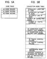
- Figs. 5A to 5C are diagrams showing detailed contents of various tables included in the road unit.
- the node table has node record #0, node record #1, etc. which correspond to all nodes included in the map sheet of interest.
- a node number is sequentially assigned, starting from #0, to each node record in accordance with the layout.
- Each node record represents the storage location of the connection node table corresponding to each node.
- connection node table includes, for each of the existing nodes:
- the link table includes a plurality of link records which is sorted in the order of the link number corresponding to all links included in the map sheet of interest.
- Each link record includes:
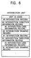
- Fig. 6 is a diagram showing detailed contents of the intersection unit.
- the intersection unit includes, for each intersection, unit ID code, an intersection record having information on the intersection itself, an intersection direction information record having information on the destination and the like of the road extending from the intersection, and an intersection lane information record having data on each lane of the roads constituting the intersection.
- each intersection record corresponds to each of the existing intersections, and includes:
- the navigation controller 1 is provided with a data buffer 16 for displaying a guiding image for a predetermined map image or an intersection, an auxiliary image showing the positional relationship between the guiding image and the intersection, or the like, a map reading control unit 18, a map-drawing unit 20, a VRAM (Video Random Access Memory) 22, an image synthesis unit 26, an intersection guiding image drawing unit 46, an auxiliary-image drawing unit 48, a vehicle position computing unit 30 for performing computation of the position of the vehicle, map-matching processing, route-search processing, route-guiding processing, as well as for outputting the results of these, a route-search processing unit 36, a guiding-route drawing unit 42, a remote-control control unit 60 for causing various operation screens for a user to be displayed or causing operation instructions from the remote control unit 4 to be sent to each unit, a cursor-position computing unit 62, and an operation screen generating unit 64.
- a data buffer 16 for displaying a guiding image for a predetermined map image or an intersection, an auxiliary
- the data buffer 16 is provided for temporarily storing map data read by the disk reading device 3 from the DVD 2.
- the map reading control unit 18 reads from the DVD 2 map data required for map display by sending a read request for a predetermined range of map data including the position of the vehicle to the disk read device 3, and stores the map data in the data buffer 16.
- the map-drawing unit 20 creates map image data to display the neighborhood of the vehicle in a three-dimensional manner based on the map data stored in the data buffer 16.
- the map image data according to the present embodiment is created based on a viewpoint which is set in accordance with a case in which a user sits in the driver's seat of the vehicle in a predetermined posture and looks ahead. Because of this, a map image created by the map-drawing unit 20 and displayed by the display device 9 that is a view observed from the driver's seat is realized in a virtual manner. An actual example of the display is described hereinafter.
- two-dimensional map data representing planar shapes such as building or roads included in the background layer undergoes a rotation coordinate-transformation in accordance with the traveling direction of the vehicle.
- a bird's eye view (referred to this as "bird's eye view A") is created by performing a predetermined projection transformation processing on the transformed two-dimensional map data based on the view position in which the direction of view is set to be along the traveling direction of the vehicle and the position thereof is set to be the position of the vehicle (the driver's seat).
- a bird's eye view (referred to this as "bird's eye view B") is created by performing a predetermined projection transformation processing based on the position of the view.
- the above-described bird's eye view A corresponds to the planar shape of the lower part of buildings and the like
- the bird's eye view B corresponds to the planar shape of the upper part of buildings and the like. Therefore, by connecting the vertices in the bird's eye view A and the corresponding vertices in the bird's eye view B, a three-dimensional image of the buildings and the like are obtained.
- the map image data displayed in a three-dimensional manner can be obtained.
- the map image data created by the map drawing unit 20 is stored in the VRAM 22 and then is read by the map synthesis unit 26.
- the image synthesis unit 26 performs image synthesis by superposing the map image data read from the VRAM 22 and image data output from each of the intersection guiding-image drawing unit 46, the auxiliary-image drawing unit 48, and the operation-screen generating unit 64.
- the image which is synthesized by the image synthesis unit 26 is displayed on the screen of the display device 9.
- the vehicle-position computing unit 30 computes the position of the vehicle based on the detected data from the GPS receiver 5 and the vehicle relative-position sensor 6. In addition, the vehicle-position computing unit 30 corrects the position of the vehicle by performing map-matching processing when the computed position of the vehicle is not on any of the roads on the map data.
- the route-search processing unit 36 searches for a traveling route linking between the preset destination and the starting place. For example, under various conditions such as a minimum distance condition or a minimum time condition, such a guiding route to minimize the cost is set. As a typical method for route searching, the Dijkstra method or a bread-first search method is known.
- the guiding-route drawing unit 42 draws the guiding routes set by the route-search processing unit 36 over the map image.
- intersection guiding-image drawing unit 46 Based on the map data stored in the data buffer 16, the intersection guiding-image drawing unit 46 creates guiding image data for displaying information on intersections and the like which are within a predetermined distance from the intersection that the vehicle is expected to pass or within a predetermined distance from the position of the vehicle.
- traffic lights, one-way traffic signs, "DO NOT ENTER" signs, lane information, route numbers, and intersection names are considered as guiding images.
- the auxiliary-image drawing unit 48 creates an auxiliary image showing which location in the map image corresponds to each of the guiding images created by the above-described intersection guiding-image drawing unit 46.
- predetermined shadows are attached to the traffic lights and the traffic signs while predetermined leader lines are attached to intersection information arranged by lane information, route number, and intersection name.
- the above-described shadows and the leader lines correspond to auxiliary images. An actual example of the display is described hereinafter.
- the overall navigation apparatus and the navigation controller 1 have the above-described constructions.
- a case in which no route guiding is performed is described.
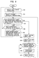
- Fig. 8 is a flow chart showing the operation procedure of the navigation apparatus when the guiding image and the auxiliary image for the corresponding intersection are displayed.
- the intersection guiding-image drawing unit 46 specifies the intersection (hereinafter, referred to this as "intersection expected to be passed") that the vehicle is to pass next based on the current position and the traveling direction of the vehicle computed by the vehicle-position computing unit 30 and the map data stored in the data buffer 16 (step 100).
- the intersection guiding-image drawing unit 46 specifies the neighboring intersection that the vehicle will possibly pass (step 101).
- intersection node expected to be passed is N0 and intersection nodes corresponding to the neighboring intersections extracted in processing at step 101 are N1, N2, N3, and N4, the intersections that the vehicle will possibly pass can be specified by checking the road attribute flags (see Fig. 5 C) corresponding to the links connected between the node N0 and nodes N1, N2, N3, and N4.
- the intersection guiding-image drawing unit 46 determines whether intersections newly come into a region within a predetermined distance from the position of the vehicle (step 102). For example, when the above-described predetermined distance is set to be 300 m from the position of the vehicle, the intersection guiding-image drawing unit 46 computes, based on the map data stored in the data buffer 16, the distances from the position of the vehicle computed by the vehicle-position computing unit 30 to each of the intersections and then determines whether there is any intersection whose computed distance is within 300 m. When any intersection comes into the region within the predetermined distance from the position of the vehicle, the intersection guiding-image drawing unit 46 reads intersection information corresponding to this intersection from the map data stored in the data buffer 16 (step 103).
- traffic lights, one-way signs, "DO NOT ENTER” signs, lane information, route numbers, and intersection names are considered as the intersection information.
- information on the presence or the absence of traffic lights, or the intersection name can be obtained from the above-described intersection record shown in Fig. 7 while information on each of lane information, route number, and one-way traffic can be obtained from link records shown in the above-described Fig. 5C.
- "DO NOT ENTER" it can be determined by obtaining one-way traffic information from the above-described link records and checking the directions of the one-way traffic roads from the obtained information.
- a guiding image representing "DO NOT ENTER" should be displayed in the neighborhood of a meeting point between the intersection image corresponding to the node A and the road image corresponding to the link B.
- the auxiliary-image drawing unit 48 creates auxiliary image data corresponding to each guiding image data (step 104).
- auxiliary image data An actual example of the display of the auxiliary image is described hereinafter.
- the map-drawing unit 20 determines whether map images of buildings and the like are located in such a position to block guiding images and auxiliary images when observed from the viewing position set in the position of the vehicle (step 105).
- the map drawing unit 20 creates the map image data obtained by applying transparent processing to these buildings and the like (step 106).
- the map-drawing unit 20 obtains positional relationships among each of the images observed from the viewing position.
- the map-drawing unit 20 determines whether transparent processing needs to be applied to the buildings and the like in accordance with this result.
- the map image data is created so that frames are drawn and corresponding side faces are filled.
- a negative determination result occurs in the determination processing at step 105. In this case, the above-described transparent processing is not performed.
- the guiding image data and the auxiliary image data created due to the above-described processing as well as the map image data created by the map drawing unit 20 are synthesized by the image synthesis unit 26.
- the image based on this synthesized image data is displayed on the display device 9 (step 107).
- image display is performed, the process proceeds back to step 102 in which operations after the determination of whether intersections newly comes into the region within the predetermined distance from the position of the vehicle repeat.
- the intersection guiding image drawing unit 46 creates guiding image data having different display areas from one another in accordance with the importance of each intersection.
- the importance of each intersection is determined in accordance with the distance from the position of the vehicle to the intersection.
- the display area of the guiding image corresponding to the intersection having greater importance becomes larger.
- the map image data when the map image data is created, the map image data is created so that the buildings and the like within the predetermined distance from the position of the vehicle are not displayed in a three-dimensional manner. Therefore, according to the navigation apparatus of the present embodiment, a map image can be displayed which is similar to the view the user actually observes from the driver's seat, and, moreover, which enables the appearance of the intersection that the vehicle is to pass hereafter to be easily recognized. An actual example of the display of these map images is described hereinafter.
- the intersection guiding image drawing unit 46 determines, based on the position of the vehicle computed by the vehicle-position computing unit 30, whether the vehicle passed the intersection expected to be passed (step 108). In a case in which the vehicle does not yet pass the intersection expected to be passed, the process proceeds back to the determination processing at step 102. Processing after the determination of whether any intersection comes into the region within the predetermined distance from the position of the vehicle repeats.
- intersection guiding image drawing unit 46 and the auxiliary-image drawing unit 48 instruct the map image drawing unit 20 to erase the guiding images and the auxiliary images which are out of the traveling direction (step 109).
- the intersections out of the traveling direction can be extracted by checking, from among the neighboring intersections specified in the above described processing at step 101, the intersections included in roads other than the road which the vehicle travels along after passing the intersection expected to be passed (the road which the vehicle currently travels along), the intersection guiding-image drawing unit 46 creates only the guiding image data corresponding to the other intersections which exclude the guiding images corresponding to these extracted intersections.
- the guiding image data is output to the map-drawing unit 20 and the auxiliary-image drawing unit 48. Since the auxiliary-image drawing unit 48 creates the auxiliary image data corresponding to the guiding image data output from the intersection guiding-image drawing unit 46, as a result, the auxiliary image data ends up being created in which the auxiliary images corresponding to the guiding images of the intersections out of the traveling direction are erased. Therefore, the guiding image data, the auxiliary image data, and the map image data created by the map-drawing unit 20 are synthesized, and, by performing display based on this synthesized image data, a map image is displayed in which the guiding images and the auxiliary images corresponding to the intersections off the traveling direction are erased. After the map image is displayed, the process proceeds back to step 100, and processing after the operation of specifying the next intersection expected to be passed repeats.
- Fig. 9 shows one example of intersection guiding-images shown on the navigation apparatus according to the present embodiment.
- Fig. 9 the appearance in which the guiding images and the auxiliary images are displayed on the map image created by setting the viewpoint at the position of the vehicle (driver's seat) is described.
- guiding images 110, 112, 114, 116, and 118 are guiding images that correspond to an intersection 100 in which the guiding image 110 represents the traffic light, the guiding image 112 represents the "DO NOT ENTER" sign, the guiding image 114 represents the route number and the intersection name, the guiding image 116 represents the lane information, and the guiding image 118 represents the one-way traffic sign.
- Guiding images 210, 212, and 214 are guiding images that correspond to an intersection 200 in which the guiding image 210 represents the traffic light, the guiding image 212 represents the route number and the intersection name, and the guiding image 214 represents lane information.
- each guiding image corresponding to the intersection 100 is displayed in size larger than each guiding image corresponding to the intersection 200.
- auxiliary images 130, 132, and 134 correspond to guiding images of the intersection 100 and auxiliary images 230 and 232 correspond to guiding images of the intersection 200.
- the auxiliary image 130 corresponds to the guiding image 110 (traffic light) and the auxiliary image 132 corresponds to the guiding image 112 (one-way traffic sign).
- these auxiliary images 130 and 132 are provided on the corresponding roads right beneath the guiding images 110 and 112, respectively, and they represent artificial shadows which are created when light is irradiated toward these guiding images from above.
- the auxiliary image 134 corresponds to the guiding image 114 (the route number and the intersection name) and the guiding image 116 (lane information). In the three-dimensional space virtually realized by the map image, it represents a cylindrical leader line extending in the direction of the guiding images 114 and 116 from a predetermined position in the intersection 100.
- auxiliary image 230 represents an artificial shadow which is created so as to correspond to the guiding image 210 (traffic light).
- the auxiliary image 232 represents a cylindrical leader line which is created so as to correspond to the guiding image 212 (route number and intersection name) and the guiding image 214 (lane information).
- a building B2 which is located in such a position so as to block the guiding image 118 (one-way traffic) has transparent processing applied thereto so that filling corresponding to side faces thereof is cancelled and only frames thereof are left.
- the frames corresponding to the building B2 are represented with dashed lines.
- the frames may be represented with straight lines of gray color or the like, or may be represented with lines which are thinner than the frames of other buildings.
- side faces of the building are arranged to be semitransparent so that the guiding image 118 which is behind the building is observed through it.
- the guiding image 118 which is supposed to be hidden by the building B2 observed from the viewpoint becomes artificially observed through the building B2.
- transparent processing should be performed by applying the same processing as is applied to the guiding image in the above-described manner.
- the navigation apparatus displays guiding images of the intersection that the vehicle is expected to pass hereafter and guiding images of its neighboring intersections
- a predetermined auxiliary image corresponding to each of the guiding images is created and displayed, the driver or the like can easily recognize the relationships between each guiding image and each intersection on the map image.
- the importance of each guiding image can be easily visually recognized.
- transparent processing to the buildings and the like which are located in such a position to blocked the guiding images when observed from the position of the viewpoint, the positional relationship between the guiding images and the map images can be easily recognized. Since the map images of the buildings and the like within the predetermined distance from the position of the vehicle are not allowed to be displayed, there is an advantage in that the appearances of the intersections which the vehicle is to pass hereafter can be easily recognized.
- the viewing position is set in the position of the vehicle (the driver seat).
- the viewing position is not necessarily limited to this.
- the viewing position may be set above the position of the vehicle.
- other than guiding images for the intersections the vehicle is expected to pass hereafter (intersections expected to be passed) one intersection is extracted for each traveling road from among the intersections which the vehicle will possibly pass and which are the closest to the intersections to be passed.
- the number of extracted intersections is not necessarily limited to one and the guiding images may be arranged to be created by extracting two or more intersections. In this case, an order of priority is assigned to each extracted intersection in accordance with the distance from the intersection expected to be passed to each intersection, the display areas of the corresponding guiding display images as to each intersection should be arranged to be varied.
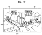
- Fig. 10 is an illustration showing an example display when the route guiding is performed. As shown in Fig.
- processing should be arranged to be performed so that a guiding route image 300 is further pasted onto the road corresponding to the guiding route, an arrow image 310 representing the traveling direction of the vehicle is pasted onto the intersection, and the lanes (the straight lane in the middle of the guiding image 116 and the right-turn lane in the right side of the guiding image 214) are filled with a noticeable color in accordance with lane information indicated by the guiding images 116 and 214 (lane guidance).
- the intersection guiding images may be arranged to be created by obtaining intersection information corresponding to the intersections expected to be passed in order of its passing expectancy. In this case, since there is no need to display the intersections which the vehicle is not expected to pass and so which do not require guiding image display, a complicated display can be prevented, which leads to visual neatness. In addition, processing of extracting the intersections at which guiding images are displayed can be simplified.
- the display areas of guiding images are varied in accordance with the order of priority of each intersection.
- important guiding images may be arranged so as to be visually recognized.
- each guiding image may be displayed so as to gradually float from roads in the neighborhood of the intersection (roads realized on the map image) corresponding thereto.
- Figs. 11A to 11D are illustrations showing one example of display in which a guiding image gradually floats.
- the "DO NOT ENTER" sign gradually floats.
- the one-way traffic sign on the road of the map image is displayed so as to gradually reveal its appearance from under the road, and, finally, the sign is shown where it is supposed to be shown.
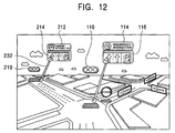
- the guiding images corresponding to each intersection are desired to be displayed superposed one after another in this region corresponding to the sky.
- Fig. 12 is an illustration showing one example of the case in which the guiding images corresponding to each intersection are displayed superposed one after another in the region corresponding to the sky.
- Each of the guiding images 110, 114, 116, 210, 212, and 214 is displayed superposed one after another in the region corresponding to the sky.
Abstract
Description
- The present invention relates to a navigation apparatus displaying intersection information and the like which is superposed on a map image in the neighborhood of a user's vehicle.
- Generally, a car navigation apparatus detects the current position of a vehicle, reads map data in the neighborhood thereof from a data storage medium such as CD (Compact Disc) or DVD (Digital Versatile Disc), and displays it on a screen. A vehicle position mark representing the position of the vehicle is displayed in the middle of the screen. In accordance with traveling of the vehicle, the map data in the neighborhood is scrolled while centered on this vehicle position mark, so that map information in the neighborhood of the vehicle is always shown. When an intersection approaches, intersection guiding images of traffic signals, traffic signs (one-way traffic sign and the like), a route number, the number of lanes, the intersection name, and the like are shown superposed one after another.
- Recently, a map image in the traveling direction of the vehicle shown using a bird's eye view, in which the position of viewing is set at a predetermined position above the vehicle, is commonly used. When the map image are shown using a bird's eye view in this manner, compared to a case in which the map image is shown in a plan view (in a two-dimensional manner), since the image which is more similar to the view actually observed by a driver is shown, there is an advantage in that the driver can easily recognize the traveling direction of the vehicle.
- When a map image in neighborhood of a vehicle is shown using a bird's eye view in the above-described manner, there is a disadvantage in that perspective of the displayed map image is hard to recognize. In particular, when the displayed map image including a plurality of intersections and guiding images which represent information (traffic lights, the presence or absence of traffic control, lane information, and the like) for each intersection is displayed at the same time, it is difficult to recognize the corresponding relationship between the guiding images and the intersections as to which guiding images belong to which intersections.
- The present invention is made in view of such problems. The object thereof is to provide a navigation apparatus which enables the position of the map corresponding to each of various guiding images to be easily recognized.
- To this end, there is provided a navigation apparatus including a map-image creating device for creating a map image observed ahead, in the traveling direction, of a vehicle from a predetermined position of a viewpoint, a guiding-image creating device for creating a guiding image including information on a predetermined intersection included in the map image, an auxiliary-image creating device for creating an auxiliary image showing which intersection included in the map image concerns the guiding image, and an image display device for synthesizing the guiding image created by the guiding-image creating device and the auxiliary image created by the auxiliary-image creating device on the map image created by the map-image creating device and for displaying the synthesized image.
- Since the auxiliary image makes the corresponding relationships between the guiding images and the intersections clear, a user such as the driver of the vehicle can easily recognize the location on the map image corresponding to the guiding images.
- In the navigation apparatus, the guiding image may display information on the intersections within a predetermined distance from the position of the vehicle.
- In the navigation apparatus, the auxiliary image may include a leader line extending from a predetermined position in the intersection to the guiding image.
- In the navigation apparatus, the guiding image may include one of a route number, lane information, and an intersection name.
- In the navigation apparatus, the guiding-image creating device may set the display area or the display color of the guiding image in a variable manner in accordance with the distance between a corresponding intersection and the position of the vehicle.
- Since the importance of each of the guiding images corresponding to an intersection in the neighborhood of the position of the vehicle is great, by varying the area or the display color of this guiding image so that the guiding image appears noticeable, at the sight of this, the user can positively recognize guiding information on the highly important intersection.
- In the navigation apparatus, preferably, the map image which is created by the map-image creating device includes a region corresponding to the sky and the image display device displays the guiding images superposed one after another in the region corresponding to the sky included in the map image.
- Generally, since information on roads, neighboring facilities, and the like are important as a map image, by displaying the guiding information superposed one after another in the region corresponding to the sky, information on the roads and the like, which is essentially important, can be prevented from being visually blocked and a wasteful region of the display screen can effectively used.
- In the navigation apparatus, the map-image creating device may create map image data in which a building is displayed in a three-dimensional manner so as to look like that which a user observes ahead, in the traveling direction, of the vehicle from the predetermined position of the viewpoint.
- In the navigation apparatus, a building within a predetermined distance from the position of the vehicle may be shown using only map image data representing the bottom face thereof.
- In the navigation apparatus, when a guiding route is set, the guiding image creating device may create a guiding-image including information on the intersections along the guiding route.
- When a guiding route is set on the map image, preferably, the above-described guiding-image creating device creates the guiding images corresponding to each of the intersections along the guiding route. When the guiding route is set, since it is assumed to travel along this guiding route, by causing the guiding images corresponding to the intersections along this guiding route to be displayed with priority, display of unnecessary guiding images is omitted and good visibility can be obtained.
- In the navigation apparatus, for intersections not expected to be passed, the guiding-image creating device may not display the guiding images of the intersections.
- Embodiments of the invention will now be described, by way of example only, with reference to the accompanying drawings, in which:
- Fig. 1 is a diagram showing the overall construction of a car navigation apparatus according to one embodiment;
- Fig. 2 is a diagram showing the contents of map data for each map sheet;
- Fig. 3 is a diagram showing detailed contents of a road name table included in a character layer of a drawing unit;
- Fig. 4 is a diagram showing detailed contents of various tables in a road unit;
- Figs. 5A to 5C are diagrams showing detailed contents of various tables in the road unit;
- Fig. 6 is a diagram showing detailed contents of an intersection unit;
- Fig. 7 is a diagram showing detailed contents of an intersection record;
- Fig. 8 is a flow chart showing an operation procedure of the navigation apparatus when guiding and auxiliary images for an intersection are displayed;
- Fig. 9 is an illustration showing one example of the intersection guiding image displayed on the navigation apparatus according to the present embodiment;
- Fig. 10 is an illustration showing a sample display in a case in which route guiding is performed;
- Figs. 11A to 11D are illustrations showing one example in which the guiding image gradually floats; and
- Fig. 12 is an illustration showing one example of a case in which the guiding images corresponding to each intersection are displayed superposed one after another in a region corresponding to the sky.
-
- Fig. 1 is a diagram showing the overall construction of the car navigation apparatus according to one embodiment which the present invention is applied to. The navigation apparatus shown in Fig. 1 is provided with a
navigation controller 1 for controlling the entirety of the apparatus, aDVD 2 for storing various map data which is required for map display, route searching, and the like, adisk reading device 3 for reading the map data stored in thisDVD 2, aremote control unit 4 which is an operation unit for having a user input various instructions, aGPS receiver 5 and a vehicle relative-position sensor 6 for detecting the position and the bearing of a user's vehicle, and adisplay device 9 for displaying a map image, and information of intersections and the like superposed thereon. - The above-described
disk reading device 3 has one ormore DVDs 2 mountable therein and reads the map data from any of theDVDs 2 under control of thenavigation controller 1. The mounted disks are not necessarily DVDs and may be CDs. Furthermore, both DVDs and CDs are selectively mountable in thedisk read device 3. - The
remote control unit 4 is provided with various operation keys such as a search key for inputting a route-search instruction, a route-guidance mode key used for a route-guidance mode setting, a destination input key, a right-left/up-down cursor key, a map scale-down/scale-up key, and a setting key for confirming an item at the cursor position on the displayed screen. Theremote control unit 4 transmits, to thenavigation controller 1, an infrared signal in accordance with the key operation state. - The
GPS receiver 5 receives electromagnetic waves transmitted from a plurality of GPS satellites, computes the absolute position and the bearing of the vehicle (the bearing of the vehicle is computed based on the current position of the vehicle and the position of the vehicle at one sampling time Δt before the current time by performing three-dimensional or two-dimensional position-determining processing), and outputs them along with the position-determination time. The vehicle relative-position sensor 6 is provided with an angular sensor such as a vibration gyro for detecting the vehicle rotation angle as a relative bearing and a distance sensor for outputting one pulse per predetermined distance traveled, whereby the relative position and the bearing of the vehicle is detected. - Based on the map data output from the
navigation controller 1, thedisplay device 9 displays map information in the neighborhood of the vehicle as well as a starting position mark, a destination mark, and the like, or displays guiding routes on this map. - Next, the map data recorded in the
DVD 2 is described in detail. The map data recorded in theDVD 2 consists of rectangular map sheets which are defined by a predetermined range of longitudes and latitudes and which are treated as a unit. Each map sheet of the map data is identified by specifying a map sheet number, whereby it can be read. Fig. 2 is a diagram showing the contents of each map sheet of the map data. As shown in Fig. 2, each map sheet of the map data includes (1) a drawing unit consisting of various data required for map displaying, (2) a road unit consisting of data required for various processing such as map matching, route searching, and route guidance, and (3) an intersection unit consisting of detailed data of intersections and the like. The above-described drawing unit includes data for a background layer required for displaying buildings or rivers and data for a character string layer required for displaying the names of cities, towns, and villages, the names of roads, and the like. The above-described background layer further includes data for the heights of buildings for displaying the buildings in the neighborhood of an intersection in a three-dimensional manner. The data for the heights of the buildings may be represented in meters or the like, or may be represented by the number of the floors thereof. When the height is represented by the number of the floors of the building, a conversion equation, - Fig. 3 is a diagram showing detailed contents of a road name table included in the character string layer of the drawing unit. As shown in Fig. 3, the road name table includes a road name record for each road contained in the map sheet of interest. Each road name record includes:
- (a) a route number;
- (b) a road type code representing the type (an expressway, a city expressway, a national highway or the like) of this road;
- (C) a route code corresponding to the route number of the national highway, a prefectural highway, or the like;
- (d) a route name "kana" (Japanese phonetic syllabary)-character string; and
- (e) a route name character string.
-
- In the road unit shown in Fig. 2, a line connecting between an intersection of a road and another intersection in its neighborhood is called a link and an intersection to which more than one link is connected is called a node. Fig. 4 is a diagram showing detailed contents of various tables included in the road unit. As shown in Fig. 4, the road unit includes a unit header for identifying the road unit, a connection node table for storing detailed data of the entirety of the nodes, a node table for showing the storage location of the connection node table, and a link table storing the detailed data of the link specified by two neighboring nodes.
- Figs. 5A to 5C are diagrams showing detailed contents of various tables included in the road unit. As shown in Fig. 5A, the node table has
node record # 0,node record # 1, etc. which correspond to all nodes included in the map sheet of interest. A node number is sequentially assigned, starting from #0, to each node record in accordance with the layout. Each node record represents the storage location of the connection node table corresponding to each node. - As shown in Fig. 5B, the connection node table includes, for each of the existing nodes:
- (a) the normalized longitude and normalized latitude;
- (b) "node attribute flags " including an intersection node flag representing whether this node is an intersection node, a neighboring node flag representing whether the node is located at the boundary with another map sheet, and branching information representing whether another link is branched at this node, and, if it is branched, whether the shape of branching links corresponds to a 'T' or a 'Y' shape;
- (c) "number of connecting nodes" representing, when there are links having this node as ends thereof, the number of the nodes which constitute the other ends thereof;
- (d) "number of traffic controls" when links connected to this node have traffic controls such as "no U-turn" or "no right-turn";
- (e) connection node records, having the same number as the number of links, each of which represents the link number of each link having this node as one node thereof;
- (f) a traffic control record, when the above-described traffic control exists, representing detailed contents of the traffic controls in accordance with the number of traffic controls;
- (g) "neighboring node record", when this node is located in the boundary with another map sheet, representing the location of the connection node table of the node on the neighboring map sheet corresponding to this node; and
- (h) the storage location and the size of the corresponding intersection record in the intersection unit when this node is an intersection node.
-
- As shown in Fig. 5C, the link table includes a plurality of link records which is sorted in the order of the link number corresponding to all links included in the map sheet of interest. Each link record includes:
- (a) the link ID which is a code attributed to each link chiefly for route-search display;
- (b)
node number 1 andnode number 2 for specifying two nodes at both ends of the link; - (c) the distance of the link;
- (d) cost required for traveling via this link;
- (e) various road attribute flags including road attribute information (the presence or the absence of one-way traffic and the like) attached to this link;
- (f) a road type flag representing whether the road type of the actual road corresponding to this link is an express highway or a general road and representing the width of the road in meters; and
- (g) the route number assigned to the road corresponding to this link.
-
- Fig. 6 is a diagram showing detailed contents of the intersection unit. As shown in Fig. 6, the intersection unit includes, for each intersection, unit ID code, an intersection record having information on the intersection itself, an intersection direction information record having information on the destination and the like of the road extending from the intersection, and an intersection lane information record having data on each lane of the roads constituting the intersection.
- As shown in Fig. 7, each intersection record corresponds to each of the existing intersections, and includes:
- (a) "intersection information flag" including a signal flag representing whether a traffic light exists at this intersection;
- (b) "number of crossings of intersection" showing the number of crossings of this intersection;
- (c) the display coordinates of the intersection name when the intersection name is displayed;
- (d) the intersection name character string to be displayed; and
- (e) the link ID of each of the links constituting this intersection and the storage locations (having the same number as the number of crossings of the intersection) of the intersection direction information records corresponding to this link.
-
- Next, the detailed construction of the
navigation controller 1 shown in Fig. 1 is described. Thenavigation controller 1 is provided with adata buffer 16 for displaying a guiding image for a predetermined map image or an intersection, an auxiliary image showing the positional relationship between the guiding image and the intersection, or the like, a mapreading control unit 18, a map-drawingunit 20, a VRAM (Video Random Access Memory) 22, animage synthesis unit 26, an intersection guidingimage drawing unit 46, an auxiliary-image drawing unit 48, a vehicleposition computing unit 30 for performing computation of the position of the vehicle, map-matching processing, route-search processing, route-guiding processing, as well as for outputting the results of these, a route-search processing unit 36, a guiding-route drawing unit 42, a remote-control control unit 60 for causing various operation screens for a user to be displayed or causing operation instructions from theremote control unit 4 to be sent to each unit, a cursor-position computing unit 62, and an operationscreen generating unit 64. - The
data buffer 16 is provided for temporarily storing map data read by thedisk reading device 3 from theDVD 2. When the vehicleposition computing unit 30 computes the position of the vehicle, the mapreading control unit 18 reads from theDVD 2 map data required for map display by sending a read request for a predetermined range of map data including the position of the vehicle to the disk readdevice 3, and stores the map data in thedata buffer 16. - The map-drawing
unit 20 creates map image data to display the neighborhood of the vehicle in a three-dimensional manner based on the map data stored in thedata buffer 16. The map image data according to the present embodiment is created based on a viewpoint which is set in accordance with a case in which a user sits in the driver's seat of the vehicle in a predetermined posture and looks ahead. Because of this, a map image created by the map-drawingunit 20 and displayed by thedisplay device 9 that is a view observed from the driver's seat is realized in a virtual manner. An actual example of the display is described hereinafter. - Here, in the above-described map-drawing
unit 20, one example of a specific method for creating the map image data in order to perform three-dimensional display is described. Initially, two-dimensional map data representing planar shapes such as building or roads included in the background layer undergoes a rotation coordinate-transformation in accordance with the traveling direction of the vehicle. Next, a bird's eye view (referred to this as "bird's eye view A") is created by performing a predetermined projection transformation processing on the transformed two-dimensional map data based on the view position in which the direction of view is set to be along the traveling direction of the vehicle and the position thereof is set to be the position of the vehicle (the driver's seat). After translating the two-dimensional map data in the direction of the height based on height data included in the background layer, a bird's eye view (referred to this as "bird's eye view B") is created by performing a predetermined projection transformation processing based on the position of the view. The above-described bird's eye view A corresponds to the planar shape of the lower part of buildings and the like, and the bird's eye view B corresponds to the planar shape of the upper part of buildings and the like. Therefore, by connecting the vertices in the bird's eye view A and the corresponding vertices in the bird's eye view B, a three-dimensional image of the buildings and the like are obtained. By overwriting, to theVRAM 22, the three-dimensional image obtained in this manner in order of decreasing distance from the position of the view, the map image data displayed in a three-dimensional manner can be obtained. - The map image data created by the
map drawing unit 20 is stored in theVRAM 22 and then is read by themap synthesis unit 26. Theimage synthesis unit 26 performs image synthesis by superposing the map image data read from theVRAM 22 and image data output from each of the intersection guiding-image drawing unit 46, the auxiliary-image drawing unit 48, and the operation-screen generating unit 64. The image which is synthesized by theimage synthesis unit 26 is displayed on the screen of thedisplay device 9. - The vehicle-
position computing unit 30 computes the position of the vehicle based on the detected data from theGPS receiver 5 and the vehicle relative-position sensor 6. In addition, the vehicle-position computing unit 30 corrects the position of the vehicle by performing map-matching processing when the computed position of the vehicle is not on any of the roads on the map data. Under predetermined conditions, the route-search processing unit 36 searches for a traveling route linking between the preset destination and the starting place. For example, under various conditions such as a minimum distance condition or a minimum time condition, such a guiding route to minimize the cost is set. As a typical method for route searching, the Dijkstra method or a bread-first search method is known. The guiding-route drawing unit 42 draws the guiding routes set by the route-search processing unit 36 over the map image. - Based on the map data stored in the
data buffer 16, the intersection guiding-image drawing unit 46 creates guiding image data for displaying information on intersections and the like which are within a predetermined distance from the intersection that the vehicle is expected to pass or within a predetermined distance from the position of the vehicle. In the present embodiment, traffic lights, one-way traffic signs, "DO NOT ENTER" signs, lane information, route numbers, and intersection names are considered as guiding images. - The auxiliary-
image drawing unit 48 creates an auxiliary image showing which location in the map image corresponds to each of the guiding images created by the above-described intersection guiding-image drawing unit 46. To be specific, according to the present embodiment, predetermined shadows are attached to the traffic lights and the traffic signs while predetermined leader lines are attached to intersection information arranged by lane information, route number, and intersection name. The above-described shadows and the leader lines correspond to auxiliary images. An actual example of the display is described hereinafter. - The overall navigation apparatus and the
navigation controller 1 have the above-described constructions. An operation procedure of guiding image and auxiliary image display for the corresponding intersection, which are performed in parallel with map image display in the neighborhood of the vehicle, is described. Here, for simplification of the description, a case in which no route guiding is performed is described. - Fig. 8 is a flow chart showing the operation procedure of the navigation apparatus when the guiding image and the auxiliary image for the corresponding intersection are displayed. The intersection guiding-
image drawing unit 46 specifies the intersection (hereinafter, referred to this as "intersection expected to be passed") that the vehicle is to pass next based on the current position and the traveling direction of the vehicle computed by the vehicle-position computing unit 30 and the map data stored in the data buffer 16 (step 100). Next, from among the intersections in the neighborhood (hereinafter, referred to these as "neighboring intersections") of the intersection expected to be passed, the intersection guiding-image drawing unit 46 specifies the neighboring intersection that the vehicle will possibly pass (step 101). To be specific, when an intersection node expected to be passed is N0 and intersection nodes corresponding to the neighboring intersections extracted in processing atstep 101 are N1, N2, N3, and N4, the intersections that the vehicle will possibly pass can be specified by checking the road attribute flags (see Fig. 5 C) corresponding to the links connected between the node N0 and nodes N1, N2, N3, and N4. - Next, the intersection guiding-
image drawing unit 46 determines whether intersections newly come into a region within a predetermined distance from the position of the vehicle (step 102). For example, when the above-described predetermined distance is set to be 300 m from the position of the vehicle, the intersection guiding-image drawing unit 46 computes, based on the map data stored in thedata buffer 16, the distances from the position of the vehicle computed by the vehicle-position computing unit 30 to each of the intersections and then determines whether there is any intersection whose computed distance is within 300 m. When any intersection comes into the region within the predetermined distance from the position of the vehicle, the intersection guiding-image drawing unit 46 reads intersection information corresponding to this intersection from the map data stored in the data buffer 16 (step 103). - As described above, in the present embodiment, traffic lights, one-way signs, "DO NOT ENTER" signs, lane information, route numbers, and intersection names are considered as the intersection information. Among information required for creating guiding images, information on the presence or the absence of traffic lights, or the intersection name can be obtained from the above-described intersection record shown in Fig. 7 while information on each of lane information, route number, and one-way traffic can be obtained from link records shown in the above-described Fig. 5C. As to "DO NOT ENTER", it can be determined by obtaining one-way traffic information from the above-described link records and checking the directions of the one-way traffic roads from the obtained information. That is, in a case in which, among a plurality of links connected to a node A, there is a link B in which only entry in the direction of the node A can be allowed, it is possible to determine that entry from the node A to the link B is prohibited. In this case, a guiding image representing "DO NOT ENTER" should be displayed in the neighborhood of a meeting point between the intersection image corresponding to the node A and the road image corresponding to the link B.
- When the guiding image data is created, the auxiliary-
image drawing unit 48 creates auxiliary image data corresponding to each guiding image data (step 104). An actual example of the display of the auxiliary image is described hereinafter. When the guiding image data and the auxiliary image data, which correspond to each intersection coming into the region within the predetermined distance from the position of the vehicle, are created, the map-drawingunit 20 determines whether map images of buildings and the like are located in such a position to block guiding images and auxiliary images when observed from the viewing position set in the position of the vehicle (step 105). When there are the buildings or the like which block the guiding images and the auxiliary images, themap drawing unit 20 creates the map image data obtained by applying transparent processing to these buildings and the like (step 106). To be specific, by checking the coordinates of the map image data created on its own, those of the guiding image data created by the intersection guidingimage drawing unit 46, and those of the auxiliary image data created by the auxiliaryimage drawing unit 48, the map-drawingunit 20 obtains positional relationships among each of the images observed from the viewing position. The map-drawingunit 20 determines whether transparent processing needs to be applied to the buildings and the like in accordance with this result. As to the buildings which need transparent processing applied thereto, the map image data is created so that frames are drawn and corresponding side faces are filled. When there is no building or the like blocking the guiding images or the auxiliary images, a negative determination result occurs in the determination processing atstep 105. In this case, the above-described transparent processing is not performed. - The guiding image data and the auxiliary image data created due to the above-described processing as well as the map image data created by the
map drawing unit 20 are synthesized by theimage synthesis unit 26. The image based on this synthesized image data is displayed on the display device 9 (step 107). When image display is performed, the process proceeds back to step 102 in which operations after the determination of whether intersections newly comes into the region within the predetermined distance from the position of the vehicle repeat. - In the above-described processing at
step 102, in a case in which there are two or more intersections coming into the region within the predetermined distance from the position of the vehicle, the intersection guidingimage drawing unit 46 according to the present embodiment creates guiding image data having different display areas from one another in accordance with the importance of each intersection. To be specific, according to the present embodiment, the importance of each intersection is determined in accordance with the distance from the position of the vehicle to the intersection. The display area of the guiding image corresponding to the intersection having greater importance becomes larger. By thus varying the display area of the corresponding guiding image in accordance with importance of each intersection, the importance of each guiding image can be easily recognized visually. In the map-drawingunit 20 according to the present embodiment, when the map image data is created, the map image data is created so that the buildings and the like within the predetermined distance from the position of the vehicle are not displayed in a three-dimensional manner. Therefore, according to the navigation apparatus of the present embodiment, a map image can be displayed which is similar to the view the user actually observes from the driver's seat, and, moreover, which enables the appearance of the intersection that the vehicle is to pass hereafter to be easily recognized. An actual example of the display of these map images is described hereinafter. - In the above-described processing at
step 102, in a case in which no intersection is determined to come into the region within the predetermined distance from the position of the vehicle (a negative determination is made at step 102), the intersection guidingimage drawing unit 46 determines, based on the position of the vehicle computed by the vehicle-position computing unit 30, whether the vehicle passed the intersection expected to be passed (step 108). In a case in which the vehicle does not yet pass the intersection expected to be passed, the process proceeds back to the determination processing atstep 102. Processing after the determination of whether any intersection comes into the region within the predetermined distance from the position of the vehicle repeats. - In a case in which the vehicle passes the intersection expected to be passed, an affirmative determination is made in determination processing at
step 108. The intersection guidingimage drawing unit 46 and the auxiliary-image drawing unit 48 instruct the mapimage drawing unit 20 to erase the guiding images and the auxiliary images which are out of the traveling direction (step 109). To be specific, since the intersections out of the traveling direction can be extracted by checking, from among the neighboring intersections specified in the above described processing atstep 101, the intersections included in roads other than the road which the vehicle travels along after passing the intersection expected to be passed (the road which the vehicle currently travels along), the intersection guiding-image drawing unit 46 creates only the guiding image data corresponding to the other intersections which exclude the guiding images corresponding to these extracted intersections. The guiding image data is output to the map-drawingunit 20 and the auxiliary-image drawing unit 48. Since the auxiliary-image drawing unit 48 creates the auxiliary image data corresponding to the guiding image data output from the intersection guiding-image drawing unit 46, as a result, the auxiliary image data ends up being created in which the auxiliary images corresponding to the guiding images of the intersections out of the traveling direction are erased. Therefore, the guiding image data, the auxiliary image data, and the map image data created by the map-drawingunit 20 are synthesized, and, by performing display based on this synthesized image data, a map image is displayed in which the guiding images and the auxiliary images corresponding to the intersections off the traveling direction are erased. After the map image is displayed, the process proceeds back to step 100, and processing after the operation of specifying the next intersection expected to be passed repeats. - Fig. 9 shows one example of intersection guiding-images shown on the navigation apparatus according to the present embodiment. In Fig. 9, the appearance in which the guiding images and the auxiliary images are displayed on the map image created by setting the viewpoint at the position of the vehicle (driver's seat) is described. In Fig. 9, guiding
images intersection 100 in which the guidingimage 110 represents the traffic light, the guidingimage 112 represents the "DO NOT ENTER" sign, the guidingimage 114 represents the route number and the intersection name, the guidingimage 116 represents the lane information, and the guidingimage 118 represents the one-way traffic sign. Guidingimages intersection 200 in which the guidingimage 210 represents the traffic light, the guidingimage 212 represents the route number and the intersection name, and the guidingimage 214 represents lane information. In Fig. 9, when theintersection 100 corresponds to the above-described intersection expected to be passed and theintersection 200 corresponds to the proximal intersection, each guiding image corresponding to theintersection 100 is displayed in size larger than each guiding image corresponding to theintersection 200. Thus, by varying the display area of each of the corresponding guiding images in accordance with the importance of each intersection, the importance of each guiding image can be easily recognized visually. B1 shown in Fig. 9 represents an example building within the predetermined distance from the above-described position of the vehicle in which the map image data for three-dimensional display is not created and only map image data representing the bottom face of the building is displayed. By thus causing the building and the like within the predetermined distance from the position of the vehicle not to be displayed in a three-dimensional manner, the appearance of theintersection 100 is shown as an easily recognizable map image. - In Fig. 9,
auxiliary images intersection 100 andauxiliary images intersection 200. A description is made focusing on theintersection 100. Theauxiliary image 130 corresponds to the guiding image 110 (traffic light) and theauxiliary image 132 corresponds to the guiding image 112 (one-way traffic sign). In a virtual three-dimensional space realized by the map image, theseauxiliary images images auxiliary images images intersection 100. Theauxiliary image 134 corresponds to the guiding image 114 (the route number and the intersection name) and the guiding image 116 (lane information). In the three-dimensional space virtually realized by the map image, it represents a cylindrical leader line extending in the direction of the guidingimages intersection 100. By creating such anauxiliary image 134, it becomes easy to recognize that each of the guidingimages intersection 100. - Likewise, in Fig. 9, a description is made focusing on the
intersection 200. Theauxiliary image 230 represents an artificial shadow which is created so as to correspond to the guiding image 210 (traffic light). Theauxiliary image 232 represents a cylindrical leader line which is created so as to correspond to the guiding image 212 (route number and intersection name) and the guiding image 214 (lane information). By creating theseauxiliary images images intersection 200. - In Fig. 9, a building B2 which is located in such a position so as to block the guiding image 118 (one-way traffic) has transparent processing applied thereto so that filling corresponding to side faces thereof is cancelled and only frames thereof are left. In Fig. 9, in order to make the appearance of the building B2 which has undergone transparent processing easy to recognize, the frames corresponding to the building B2 are represented with dashed lines. In reality, for example, the frames may be represented with straight lines of gray color or the like, or may be represented with lines which are thinner than the frames of other buildings. Alternatively, side faces of the building are arranged to be semitransparent so that the guiding
image 118 which is behind the building is observed through it. By applying transparent processing in this manner, the guidingimage 118 which is supposed to be hidden by the building B2 observed from the viewpoint becomes artificially observed through the building B2. In the above-described example, although the case in which the auxiliary image is not blocked is described, in a case in which the auxiliary image is also blocked, transparent processing should be performed by applying the same processing as is applied to the guiding image in the above-described manner. - When the navigation apparatus according to the present embodiment displays guiding images of the intersection that the vehicle is expected to pass hereafter and guiding images of its neighboring intersections, since a predetermined auxiliary image corresponding to each of the guiding images is created and displayed, the driver or the like can easily recognize the relationships between each guiding image and each intersection on the map image. In particular, in the present embodiment, since a predetermined order of priority is set for each guiding image and the display areas of the guiding images are varied in accordance with the priority order, the importance of each guiding image can be easily visually recognized. By applying transparent processing to the buildings and the like which are located in such a position to blocked the guiding images when observed from the position of the viewpoint, the positional relationship between the guiding images and the map images can be easily recognized. Since the map images of the buildings and the like within the predetermined distance from the position of the vehicle are not allowed to be displayed, there is an advantage in that the appearances of the intersections which the vehicle is to pass hereafter can be easily recognized.
- The present invention is not limited to the above-described embodiment and various changes may be made within the spirit and the scope of the invention. For example, in the above-described embodiment, when the map image is created, the viewing position is set in the position of the vehicle (the driver seat). However, the viewing position is not necessarily limited to this. For example, the viewing position may be set above the position of the vehicle. In the above-described embodiment, other than guiding images for the intersections the vehicle is expected to pass hereafter (intersections expected to be passed), one intersection is extracted for each traveling road from among the intersections which the vehicle will possibly pass and which are the closest to the intersections to be passed. However, the number of extracted intersections is not necessarily limited to one and the guiding images may be arranged to be created by extracting two or more intersections. In this case, an order of priority is assigned to each extracted intersection in accordance with the distance from the intersection expected to be passed to each intersection, the display areas of the corresponding guiding display images as to each intersection should be arranged to be varied.
- In the above-described embodiment, the case in which the map image in the neighborhood of the vehicle is displayed without applying route guiding is described. However, the present invention can be also applied to a case in which route guiding is applied. Fig. 10 is an illustration showing an example display when the route guiding is performed. As shown in Fig. 10, when the route guiding is applied, processing should be arranged to be performed so that a guiding
route image 300 is further pasted onto the road corresponding to the guiding route, anarrow image 310 representing the traveling direction of the vehicle is pasted onto the intersection, and the lanes (the straight lane in the middle of the guidingimage 116 and the right-turn lane in the right side of the guiding image 214) are filled with a noticeable color in accordance with lane information indicated by the guidingimages 116 and 214 (lane guidance). - When route guiding is performed, since the intersections the vehicle is expected to pass are predetermined, instead of the above-described extracting processing of the nearest intersections executed from steps S101 to S103 in Fig. 8, the intersection guiding images may be arranged to be created by obtaining intersection information corresponding to the intersections expected to be passed in order of its passing expectancy. In this case, since there is no need to display the intersections which the vehicle is not expected to pass and so which do not require guiding image display, a complicated display can be prevented, which leads to visual neatness. In addition, processing of extracting the intersections at which guiding images are displayed can be simplified.
- In the above-described embodiment, the display areas of guiding images are varied in accordance with the order of priority of each intersection. By varying the colors of the guiding images, important guiding images may be arranged so as to be visually recognized.
- When the above-described guiding images are displayed, each guiding image may be displayed so as to gradually float from roads in the neighborhood of the intersection (roads realized on the map image) corresponding thereto. Figs. 11A to 11D are illustrations showing one example of display in which a guiding image gradually floats. In the figure, there are shown illustrations in which the "DO NOT ENTER" sign gradually floats. As shown in Figs. 11A to 11D, the one-way traffic sign on the road of the map image is displayed so as to gradually reveal its appearance from under the road, and, finally, the sign is shown where it is supposed to be shown. By thus causing the guiding image display to be animated, the intersection to which the guiding image ("DO NOT ENTER" sign in Figs. 11A to 11D) corresponds can be more easily recognized.
- In a case in which the map image which is created by the above-described map-drawing
unit 20 includes a region corresponding to the sky, the guiding images corresponding to each intersection are desired to be displayed superposed one after another in this region corresponding to the sky. Fig. 12 is an illustration showing one example of the case in which the guiding images corresponding to each intersection are displayed superposed one after another in the region corresponding to the sky. Each of the guidingimages
Claims (10)
- A navigation apparatus including:map-image creating means (20) for creating a map image observed ahead, in the traveling direction, of a vehicle from a predetermined position of a viewpoint;guiding-image creating means (46) for creating a guiding image including information on a predetermined intersection included in said map image;auxiliary-image creating means (48) for creating an auxiliary image showing which intersection included in said map image concerns said guiding image; andimage display means (9,26) for synthesizing said guiding image created by said guiding-image creating means (46) and said auxiliary image created by said auxiliary-image creating means (48) on said map image created by said map-image creating means (20) and for displaying the synthesized image.
- A navigation apparatus according to Claim 1, wherein said guiding image displays information on the intersections within a predetermined distance from the position of the vehicle.
- A navigation apparatus according to Claim 1 or 2, wherein said auxiliary image includes a leader line extending from a predetermined position in said intersection to said guiding image.
- A navigation apparatus according to Claim 1, 2 or 3, wherein said guiding image includes one of a route number, lane information, and an intersection name.
- A navigation apparatus according to any preceding claim, wherein said guiding-image creating means (46) sets the display area or the display color of said guiding image in a variable manner in accordance with the distance between a corresponding intersection and the position of the vehicle.
- A navigation apparatus according to any preceding claim, wherein said map image which is created by said map-image creating means (20) includes a region corresponding to the sky; andsaid image display means (9,26) displays the guiding images superposed one after another in said region corresponding to the sky included in said map image.
- A navigation apparatus according to any preceding claim, wherein said map-image creating means (20) creates map image data in which a building is displayed in a three-dimensional manner so as to look like that which a user observes ahead, in the traveling direction, of the vehicle from the predetermined position of the viewpoint.
- A navigation apparatus according to any preceding claim, wherein a building within a predetermined distance from the position of the vehicle is shown using only map image data representing the bottom face thereof.
- A navigation apparatus according to any preceding claim, wherein, when a guiding route is set, said guiding image creating means (46) creates a guiding-image including information on the intersections along said guiding route.
- A navigation apparatus according to any preceding claim, wherein, for intersections not expected to be passed, said guiding-image creating means (46) does not display the guiding images of said intersections.
Applications Claiming Priority (2)
| Application Number | Priority Date | Filing Date | Title |
|---|---|---|---|
| JP26053899A JP3908419B2 (en) | 1999-09-14 | 1999-09-14 | Navigation device |
| JP26053899 | 1999-09-14 |
Publications (3)
| Publication Number | Publication Date |
|---|---|
| EP1085299A2 true EP1085299A2 (en) | 2001-03-21 |
| EP1085299A3 EP1085299A3 (en) | 2003-12-10 |
| EP1085299B1 EP1085299B1 (en) | 2006-06-07 |
Family
ID=17349365
Family Applications (1)
| Application Number | Title | Priority Date | Filing Date |
|---|---|---|---|
| EP00307127A Expired - Lifetime EP1085299B1 (en) | 1999-09-14 | 2000-08-21 | Navigation apparatus |
Country Status (4)
| Country | Link |
|---|---|
| US (1) | US6360168B1 (en) |
| EP (1) | EP1085299B1 (en) |
| JP (1) | JP3908419B2 (en) |
| DE (1) | DE60028482T2 (en) |
Cited By (17)
| Publication number | Priority date | Publication date | Assignee | Title |
|---|---|---|---|---|
| EP1241445A2 (en) | 2001-03-15 | 2002-09-18 | Matsushita Electric Industrial Co., Ltd. | 3D Map and object displaying apparatus and method, and navigation apparatus employing the method |
| WO2006111461A1 (en) | 2005-04-19 | 2006-10-26 | Robert Bosch Gmbh | Method for three-dimensionally displaying a digital road map |
| EP1873495A1 (en) * | 2006-06-30 | 2008-01-02 | Aisin AW Co., Ltd. | Navigation apparatus with three-dimensional route guidance |
| WO2008022695A1 (en) * | 2006-08-24 | 2008-02-28 | Bayerische Motoren Werke Aktiengesellschaft | Navigation system |
| EP1936328A1 (en) * | 2006-12-22 | 2008-06-25 | Robert Bosch Gmbh | Method for representing a map segment in a navigation system and navigation system therefor |
| WO2008074561A1 (en) * | 2006-12-19 | 2008-06-26 | Robert Bosch Gmbh | Method for displaying a map section in a navigation system, and navigation system |
| EP2244242A1 (en) * | 2009-04-23 | 2010-10-27 | Wayfinder Systems AB | Method and device for improved navigation |
| EP2272056A1 (en) * | 2008-03-25 | 2011-01-12 | Thinkware Systems Corporation | Method for providing lane information and apparatus for executing the method |
| RU2454728C1 (en) * | 2011-04-15 | 2012-06-27 | Федеральное государственное военное образовательное учреждение высшего профессионального образования "Военный авиационный инженерный университет" (г. Воронеж) Министерства обороны Российской Федерации | Method to assess noise immunity of board radio electronic communication and navigation facilities |
| EP2541207A1 (en) * | 2011-07-01 | 2013-01-02 | Harman Becker Automotive Systems GmbH | Vehicle navigation device and method |
| US8406995B2 (en) | 2009-04-23 | 2013-03-26 | Vodafone Group Plc | Providing time table information |
| CN104471354A (en) * | 2012-08-10 | 2015-03-25 | 爱信艾达株式会社 | Intersection guidance system, method and program |
| DE102011088348B4 (en) * | 2010-12-20 | 2016-10-06 | Ford Global Technologies, Llc | Computer-implemented method for road marking |
| US9713963B2 (en) | 2013-02-18 | 2017-07-25 | Ford Global Technologies, Llc | Method and apparatus for route completion likelihood display |
| US9846046B2 (en) | 2010-07-30 | 2017-12-19 | Ford Global Technologies, Llc | Vehicle navigation method and system |
| US9863777B2 (en) | 2013-02-25 | 2018-01-09 | Ford Global Technologies, Llc | Method and apparatus for automatic estimated time of arrival calculation and provision |
| US9874452B2 (en) | 2013-03-14 | 2018-01-23 | Ford Global Technologies, Llc | Method and apparatus for enhanced driving experience including dynamic POI identification |
Families Citing this family (90)
| Publication number | Priority date | Publication date | Assignee | Title |
|---|---|---|---|---|
| US6904160B2 (en) * | 2000-10-18 | 2005-06-07 | Red Hen Systems, Inc. | Method for matching geographic information with recorded images |
| US20020178212A1 (en) * | 2001-03-28 | 2002-11-28 | Sun Microsystems, Inc. | Match game applet |
| JP2003172624A (en) * | 2001-12-10 | 2003-06-20 | Mitsubishi Electric Corp | Apparatus and method for searching intersection |
| US7221287B2 (en) | 2002-03-05 | 2007-05-22 | Triangle Software Llc | Three-dimensional traffic report |
| US6882934B2 (en) * | 2002-03-14 | 2005-04-19 | Matsushita Electric Industrial Co., Ltd. | Apparatus and method for displaying map |
| JP3992227B2 (en) * | 2002-04-26 | 2007-10-17 | パイオニア株式会社 | 3D information display device |
| US7827507B2 (en) * | 2002-05-03 | 2010-11-02 | Pixearth Corporation | System to navigate within images spatially referenced to a computed space |
| JP3949007B2 (en) * | 2002-05-30 | 2007-07-25 | アルパイン株式会社 | Navigation device |
| US8797402B2 (en) * | 2002-11-19 | 2014-08-05 | Hewlett-Packard Development Company, L.P. | Methods and apparatus for imaging and displaying a navigable path |
| JP4077400B2 (en) * | 2002-12-26 | 2008-04-16 | 株式会社東芝 | GUIDE INFORMATION PROVIDING DEVICE, SERVER DEVICE, GUIDE INFORMATION PROVIDING METHOD, AND PROGRAM FOR CAUSING COMPUTER TO PROVIDE GUIDE INFORMATION PROVIDING |
| KR100648342B1 (en) * | 2003-02-10 | 2006-11-23 | 엘지전자 주식회사 | navigation system and the operating method |
| US20040218910A1 (en) * | 2003-04-30 | 2004-11-04 | Chang Nelson L. | Enabling a three-dimensional simulation of a trip through a region |
| US7526718B2 (en) * | 2003-04-30 | 2009-04-28 | Hewlett-Packard Development Company, L.P. | Apparatus and method for recording “path-enhanced” multimedia |
| KR100703444B1 (en) * | 2003-06-03 | 2007-04-03 | 삼성전자주식회사 | Device and method for downloading and displaying a images of global position information in navigation system |
| US7610145B2 (en) | 2003-07-25 | 2009-10-27 | Triangle Software Llc | System and method for determining recommended departure time |
| JP2005069776A (en) * | 2003-08-21 | 2005-03-17 | Denso Corp | Display method for vehicle, and display device for vehicle |
| JP4093144B2 (en) * | 2003-08-22 | 2008-06-04 | 株式会社デンソー | Vehicle display device |
| CA2559726C (en) | 2004-03-24 | 2015-10-20 | A9.Com, Inc. | System and method for displaying images in an online directory |
| JP4423114B2 (en) * | 2004-06-02 | 2010-03-03 | アルパイン株式会社 | Navigation device and its intersection guidance method |
| US20050280558A1 (en) * | 2004-06-18 | 2005-12-22 | Christopher McLeod | A remote control device containing a Global Positioning System (GPS) device emitting a geographical signal processed in this same remote control to produce a signal which then elicits the selection of a map file recorded on a Digital Video Disc (DVD) on a separate digital video disc player connnected to a video display device also separate from this remote control toward display and mainpulation of this and other map files and the geographic position of this remote control |
| JP4476723B2 (en) * | 2004-07-14 | 2010-06-09 | アルパイン株式会社 | Image display device |
| JP4213097B2 (en) * | 2004-09-13 | 2009-01-21 | 三菱電機株式会社 | Car navigation system |
| JP4696248B2 (en) * | 2004-09-28 | 2011-06-08 | 国立大学法人 熊本大学 | MOBILE NAVIGATION INFORMATION DISPLAY METHOD AND MOBILE NAVIGATION INFORMATION DISPLAY DEVICE |
| US7831532B2 (en) | 2004-11-16 | 2010-11-09 | Microsoft Corporation | Precomputation and transmission of time-dependent information for varying or uncertain receipt times |
| US7519564B2 (en) | 2004-11-16 | 2009-04-14 | Microsoft Corporation | Building and using predictive models of current and future surprises |
| US7698055B2 (en) * | 2004-11-16 | 2010-04-13 | Microsoft Corporation | Traffic forecasting employing modeling and analysis of probabilistic interdependencies and contextual data |
| JP4628796B2 (en) * | 2005-01-05 | 2011-02-09 | アルパイン株式会社 | Navigation device |
| KR100657943B1 (en) * | 2005-01-07 | 2006-12-14 | 삼성전자주식회사 | Real time 3 dimensional transformation method for 2 dimensional building data and apparatus therefor, and real time 3 dimensional visualization method for 2 dimensional linear building data and apparatus using the same |
| JP4791064B2 (en) * | 2005-03-24 | 2011-10-12 | 有限会社ヴェルク・ジャパン | Navigation device with environmental sound reproduction |
| US8781736B2 (en) * | 2005-04-18 | 2014-07-15 | Navteq B.V. | Data-driven traffic views with continuous real-time rendering of traffic flow map |
| US8626440B2 (en) * | 2005-04-18 | 2014-01-07 | Navteq B.V. | Data-driven 3D traffic views with the view based on user-selected start and end geographical locations |
| US20060253246A1 (en) * | 2005-04-18 | 2006-11-09 | Cera Christopher D | Data-driven combined traffic/weather views |
| US7765055B2 (en) * | 2005-04-18 | 2010-07-27 | Traffic.Com, Inc. | Data-driven traffic views with the view based on a user-selected object of interest |
| CN101163940B (en) * | 2005-04-25 | 2013-07-24 | 株式会社吉奥技术研究所 | Imaging position analyzing method |
| JP4741328B2 (en) * | 2005-09-08 | 2011-08-03 | クラリオン株式会社 | Navigation device |
| JP2007121081A (en) * | 2005-10-27 | 2007-05-17 | Sanyo Electric Co Ltd | Navigation device and road information display method |
| JP2007133489A (en) * | 2005-11-08 | 2007-05-31 | Sony Corp | Virtual space image display method and device, virtual space image display program and recording medium |
| KR20070093484A (en) * | 2006-03-14 | 2007-09-19 | 주식회사 현대오토넷 | Apparatus for displaying traffic lane guide image of navigation using vehicle |
| JP4935145B2 (en) * | 2006-03-29 | 2012-05-23 | 株式会社デンソー | Car navigation system |
| JP2008102467A (en) * | 2006-10-19 | 2008-05-01 | Kokusai Kogyo Co Ltd | Sign object display system |
| JP4946368B2 (en) * | 2006-11-09 | 2012-06-06 | 日産自動車株式会社 | Navigation device |
| US8566028B2 (en) * | 2006-11-27 | 2013-10-22 | International Business Machines Corporation | Apparatus, system, and method for autonomously determining a set of destinations |
| WO2008099483A1 (en) * | 2007-02-15 | 2008-08-21 | Pioneer Corporation | Display controller, display control method, display control program, and recording medium |
| DE102007030345A1 (en) * | 2007-02-28 | 2008-09-04 | Navigon Ag | Navigation device and method for the graphic output of navigation instructions |
| US8260543B2 (en) * | 2007-03-29 | 2012-09-04 | Alpine Electronics, Inc. | Hidden point detection and warning method and apparatus for navigation system |
| JP4577327B2 (en) * | 2007-04-09 | 2010-11-10 | 株式会社デンソー | Map display control device and program for map display control device |
| US9037599B1 (en) * | 2007-05-29 | 2015-05-19 | Google Inc. | Registering photos in a geographic information system, and applications thereof |
| US20080309762A1 (en) * | 2007-06-12 | 2008-12-18 | Richie Howard | In-vehicle mobile digital video surveillance recorder system with GPS visual mapping and navigation |
| DE102007038463A1 (en) * | 2007-06-13 | 2008-12-24 | Navigon Ag | Method for operating a navigation system |
| US8086071B2 (en) * | 2007-10-30 | 2011-12-27 | Navteq North America, Llc | System and method for revealing occluded objects in an image dataset |
| US8244454B2 (en) * | 2008-01-07 | 2012-08-14 | Tomtom International B.V. | Navigation device and method |
| DE102008003395A1 (en) * | 2008-01-08 | 2009-07-23 | Navigon Ag | Method for operating a navigation system |
| JP4994256B2 (en) * | 2008-01-28 | 2012-08-08 | 株式会社ジオ技術研究所 | Data structure of route guidance database |
| US8346465B2 (en) * | 2008-02-26 | 2013-01-01 | Apline Electronics, Inc | Method and apparatus for determining and displaying meaningful cross street for navigation system |
| CA2720303A1 (en) * | 2008-05-02 | 2009-11-05 | Tomtom International B.V. | A navigation device and method for displaying map information |
| JP5279904B2 (en) | 2008-07-11 | 2013-09-04 | トムトム グローバル コンテント ベスローテン フエンノートシャップ | Apparatus and method for displaying a bifurcation point view |
| DE102008045994A1 (en) * | 2008-09-05 | 2010-03-11 | Volkswagen Ag | Method and device for displaying information in a vehicle |
| JP2009031308A (en) * | 2008-10-30 | 2009-02-12 | Zenrin Co Ltd | Navigation system and data structure for electronic map data |
| US8619072B2 (en) | 2009-03-04 | 2013-12-31 | Triangle Software Llc | Controlling a three-dimensional virtual broadcast presentation |
| JP5554045B2 (en) * | 2009-10-21 | 2014-07-23 | アルパイン株式会社 | Map display device and map display method |
| JP2011227071A (en) * | 2010-03-30 | 2011-11-10 | Zenrin Co Ltd | Traffic support system |
| US8892357B2 (en) * | 2010-09-20 | 2014-11-18 | Honeywell International Inc. | Ground navigational display, system and method displaying buildings in three-dimensions |
| US8849552B2 (en) | 2010-09-29 | 2014-09-30 | Ford Global Technologies, Llc | Advanced map information delivery, processing and updating |
| EP2503292B1 (en) | 2011-03-22 | 2016-01-06 | Harman Becker Automotive Systems GmbH | Landmark icons in digital maps |
| EP2503291A1 (en) * | 2011-03-22 | 2012-09-26 | Harman Becker Automotive Systems GmbH | Signposts in digital maps |
| EP2503290A1 (en) | 2011-03-22 | 2012-09-26 | Harman Becker Automotive Systems GmbH | Curved labeling in digital maps |
| WO2012159083A2 (en) | 2011-05-18 | 2012-11-22 | Triangle Software Llc | System for providing traffic data and driving efficiency data |
| US8788203B2 (en) * | 2011-05-23 | 2014-07-22 | Microsoft Corporation | User-driven navigation in a map navigation tool |
| EP2765075B1 (en) * | 2011-10-03 | 2020-07-22 | Furuno Electric Co., Ltd. | Display device, display program, and display method |
| KR101318651B1 (en) * | 2011-11-15 | 2013-10-16 | 현대자동차주식회사 | Navigation System and Displaying Method Thereof |
| US8838385B2 (en) | 2011-12-20 | 2014-09-16 | Ford Global Technologies, Llc | Method and apparatus for vehicle routing |
| US10191641B2 (en) * | 2011-12-29 | 2019-01-29 | Apple Inc. | Device, method, and graphical user interface for navigation of information in a map-based interface |
| US20150029214A1 (en) * | 2012-01-19 | 2015-01-29 | Pioneer Corporation | Display device, control method, program and storage medium |
| US10296516B2 (en) * | 2012-05-21 | 2019-05-21 | Here Global B.V. | Method and apparatus for navigation using multiple synchronized mobile devices |
| USD740832S1 (en) * | 2012-06-06 | 2015-10-13 | Apple Inc. | Display screen or portion thereof with a graphical user interface |
| USD730364S1 (en) | 2012-06-05 | 2015-05-26 | Apple Inc. | Display screen or portion thereof with a graphical user interface |
| USD719973S1 (en) | 2012-06-06 | 2014-12-23 | Apple Inc. | Display screen or portion thereof with graphical user interface |
| USD739859S1 (en) | 2012-06-06 | 2015-09-29 | Apple Inc. | Display screen or portion thereof with graphical user interface |
| JP6015227B2 (en) | 2012-08-10 | 2016-10-26 | アイシン・エィ・ダブリュ株式会社 | Intersection guidance system, method and program |
| JP5935636B2 (en) | 2012-09-28 | 2016-06-15 | アイシン・エィ・ダブリュ株式会社 | Intersection guidance system, method and program |
| US10223909B2 (en) | 2012-10-18 | 2019-03-05 | Uber Technologies, Inc. | Estimating time travel distributions on signalized arterials |
| US8977479B2 (en) | 2013-03-12 | 2015-03-10 | Ford Global Technologies, Llc | Method and apparatus for determining traffic conditions |
| US9047774B2 (en) | 2013-03-12 | 2015-06-02 | Ford Global Technologies, Llc | Method and apparatus for crowd-sourced traffic reporting |
| JP5964771B2 (en) * | 2013-03-21 | 2016-08-03 | 株式会社ジオ技術研究所 | 3D map display device, 3D map display method, and computer program |
| US9418485B2 (en) | 2013-05-31 | 2016-08-16 | Apple Inc. | Adjusting heights for road path indicators |
| JP6446784B2 (en) * | 2014-01-21 | 2019-01-09 | 株式会社デンソー | Navigation device |
| JP7061938B2 (en) * | 2018-07-17 | 2022-05-02 | 三菱電機株式会社 | Driving support device and driving support method |
| DE102019204036A1 (en) * | 2019-03-25 | 2020-10-01 | Volkswagen Aktiengesellschaft | Method for operating a navigation device and navigation device |
| JP7400356B2 (en) * | 2019-11-04 | 2023-12-19 | 株式会社アイシン | Superimposed image display device and computer program |
| US20230290156A1 (en) * | 2022-03-11 | 2023-09-14 | GM Global Technology Operations LLC | System and method for providing lane identification on an augmented reality display |
Citations (3)
| Publication number | Priority date | Publication date | Assignee | Title |
|---|---|---|---|---|
| EP0762361A1 (en) * | 1995-08-25 | 1997-03-12 | Aisin Aw Co., Ltd. | Navigation system for vehicles |
| EP0802516A2 (en) * | 1996-04-16 | 1997-10-22 | Xanavi Informatics Corporation | Map display device, navigation device and map display method |
| EP0803706A2 (en) * | 1996-04-26 | 1997-10-29 | Pioneer Electronic Corporation | Navigation apparatus with shape change display function |
Family Cites Families (9)
| Publication number | Priority date | Publication date | Assignee | Title |
|---|---|---|---|---|
| JP3511561B2 (en) | 1996-09-11 | 2004-03-29 | パイオニア株式会社 | Map information display device, navigation device, and recording medium recording navigation program |
| US5448696A (en) * | 1990-11-30 | 1995-09-05 | Hitachi, Ltd. | Map information system capable of displaying layout information |
| DE4327780C2 (en) * | 1992-08-19 | 1998-12-17 | Aisin Aw Co | Vehicle navigation system and vehicle navigation method |
| JP3568621B2 (en) | 1995-04-20 | 2004-09-22 | 株式会社日立製作所 | Map display device |
| US5983158A (en) * | 1995-09-08 | 1999-11-09 | Aisin Aw Co., Ltd. | Navigation system for vehicles |
| KR100256620B1 (en) * | 1995-10-30 | 2000-05-15 | 모리 하루오 | Navigation system |
| KR960042490A (en) * | 1995-11-09 | 1996-12-21 | 모리 하루오 | Vehicle navigation device and recording medium therefor |
| US5936553A (en) | 1997-02-28 | 1999-08-10 | Garmin Corporation | Navigation device and method for displaying navigation information in a visual perspective view |
| US6182010B1 (en) * | 1999-01-28 | 2001-01-30 | International Business Machines Corporation | Method and apparatus for displaying real-time visual information on an automobile pervasive computing client |
-
1999
- 1999-09-14 JP JP26053899A patent/JP3908419B2/en not_active Expired - Fee Related
-
2000
- 2000-08-21 EP EP00307127A patent/EP1085299B1/en not_active Expired - Lifetime
- 2000-08-21 DE DE60028482T patent/DE60028482T2/en not_active Expired - Fee Related
- 2000-09-08 US US09/657,713 patent/US6360168B1/en not_active Expired - Fee Related
Patent Citations (3)
| Publication number | Priority date | Publication date | Assignee | Title |
|---|---|---|---|---|
| EP0762361A1 (en) * | 1995-08-25 | 1997-03-12 | Aisin Aw Co., Ltd. | Navigation system for vehicles |
| EP0802516A2 (en) * | 1996-04-16 | 1997-10-22 | Xanavi Informatics Corporation | Map display device, navigation device and map display method |
| EP0803706A2 (en) * | 1996-04-26 | 1997-10-29 | Pioneer Electronic Corporation | Navigation apparatus with shape change display function |
Cited By (30)
| Publication number | Priority date | Publication date | Assignee | Title |
|---|---|---|---|---|
| EP1241445A2 (en) | 2001-03-15 | 2002-09-18 | Matsushita Electric Industrial Co., Ltd. | 3D Map and object displaying apparatus and method, and navigation apparatus employing the method |
| EP1241445A3 (en) * | 2001-03-15 | 2010-10-13 | Panasonic Corporation | 3D Map and object displaying apparatus and method, and navigation apparatus employing the method |
| WO2006111461A1 (en) | 2005-04-19 | 2006-10-26 | Robert Bosch Gmbh | Method for three-dimensionally displaying a digital road map |
| US8442762B2 (en) * | 2005-04-19 | 2013-05-14 | Robert Bosch Gmbh | Method for the three-dimensional representation of a digital roadmap |
| US20100063728A1 (en) * | 2005-04-19 | 2010-03-11 | Thomas Jung | Method for the Three-Dimensional Representation of a Digital Roadmap |
| CN101163943B (en) * | 2005-04-19 | 2016-03-23 | 罗伯特·博世有限公司 | For the method for 3-D display Digital Highway figure |
| EP1873495A1 (en) * | 2006-06-30 | 2008-01-02 | Aisin AW Co., Ltd. | Navigation apparatus with three-dimensional route guidance |
| US7835861B2 (en) | 2006-06-30 | 2010-11-16 | Aisin Aw Co., Ltd. | Navigation apparatuses, methods, and programs for generation of a 3D movie |
| WO2008022695A1 (en) * | 2006-08-24 | 2008-02-28 | Bayerische Motoren Werke Aktiengesellschaft | Navigation system |
| US7840349B2 (en) | 2006-08-24 | 2010-11-23 | Bayerische Motoren Werke Aktiengesellschaft | Navigation system and method |
| WO2008074561A1 (en) * | 2006-12-19 | 2008-06-26 | Robert Bosch Gmbh | Method for displaying a map section in a navigation system, and navigation system |
| EP1936328A1 (en) * | 2006-12-22 | 2008-06-25 | Robert Bosch Gmbh | Method for representing a map segment in a navigation system and navigation system therefor |
| CN102047301A (en) * | 2008-03-25 | 2011-05-04 | 星克跃尔株式会社 | Method for providing lane information and apparatus for executing the method |
| EP2272056A4 (en) * | 2008-03-25 | 2011-05-04 | Thinkware Systems Corp | Method for providing lane information and apparatus for executing the method |
| US9269266B2 (en) | 2008-03-25 | 2016-02-23 | Intellectual Discovery Co., Ltd. | Method for providing lane information and apparatus for executing the method |
| EP2272056A1 (en) * | 2008-03-25 | 2011-01-12 | Thinkware Systems Corporation | Method for providing lane information and apparatus for executing the method |
| CN102047301B (en) * | 2008-03-25 | 2014-04-02 | 星克跃尔株式会社 | Method for providing lane information and apparatus for executing the method |
| US9214098B2 (en) | 2009-04-23 | 2015-12-15 | Vodafone Group Services Limited | Providing navigation instructions in a three-dimension map environment having settable object transparency levels |
| US8406995B2 (en) | 2009-04-23 | 2013-03-26 | Vodafone Group Plc | Providing time table information |
| EP2244242A1 (en) * | 2009-04-23 | 2010-10-27 | Wayfinder Systems AB | Method and device for improved navigation |
| US9846046B2 (en) | 2010-07-30 | 2017-12-19 | Ford Global Technologies, Llc | Vehicle navigation method and system |
| DE102011088348B4 (en) * | 2010-12-20 | 2016-10-06 | Ford Global Technologies, Llc | Computer-implemented method for road marking |
| RU2454728C1 (en) * | 2011-04-15 | 2012-06-27 | Федеральное государственное военное образовательное учреждение высшего профессионального образования "Военный авиационный инженерный университет" (г. Воронеж) Министерства обороны Российской Федерации | Method to assess noise immunity of board radio electronic communication and navigation facilities |
| CN102853839A (en) * | 2011-07-01 | 2013-01-02 | 哈曼贝克自动系统股份有限公司 | Vehicle navigation device and method |
| EP2541207A1 (en) * | 2011-07-01 | 2013-01-02 | Harman Becker Automotive Systems GmbH | Vehicle navigation device and method |
| CN104471354A (en) * | 2012-08-10 | 2015-03-25 | 爱信艾达株式会社 | Intersection guidance system, method and program |
| US9713963B2 (en) | 2013-02-18 | 2017-07-25 | Ford Global Technologies, Llc | Method and apparatus for route completion likelihood display |
| US10369897B2 (en) | 2013-02-18 | 2019-08-06 | Ford Global Technologies, Llc | Method and apparatus for route completion likelihood display |
| US9863777B2 (en) | 2013-02-25 | 2018-01-09 | Ford Global Technologies, Llc | Method and apparatus for automatic estimated time of arrival calculation and provision |
| US9874452B2 (en) | 2013-03-14 | 2018-01-23 | Ford Global Technologies, Llc | Method and apparatus for enhanced driving experience including dynamic POI identification |
Also Published As
| Publication number | Publication date |
|---|---|
| US6360168B1 (en) | 2002-03-19 |
| EP1085299A3 (en) | 2003-12-10 |
| JP3908419B2 (en) | 2007-04-25 |
| DE60028482D1 (en) | 2006-07-20 |
| DE60028482T2 (en) | 2007-01-04 |
| EP1085299B1 (en) | 2006-06-07 |
| JP2001082969A (en) | 2001-03-30 |
Similar Documents
| Publication | Publication Date | Title |
|---|---|---|
| EP1085299B1 (en) | Navigation apparatus | |
| JP3501390B2 (en) | Car navigation system | |
| JP4486175B2 (en) | 3D map display apparatus and method | |
| KR100267542B1 (en) | Navigation system | |
| JP4964762B2 (en) | Map display device and map display method | |
| US5884218A (en) | Map indication device and navigation device | |
| US7398155B2 (en) | Car navigation system | |
| US8515664B2 (en) | Digital map signpost system | |
| US20070192020A1 (en) | Navigation System with Animated Intersection View | |
| US8880343B2 (en) | System for digital map labeling | |
| JP2002168634A (en) | Display method for three-dimensional map of on-vehicle navigation system | |
| JP2004212255A (en) | Navigation device | |
| JP4219474B2 (en) | Traveling position display device | |
| JP4100803B2 (en) | Vehicle guidance method for navigation device | |
| JP2004233333A (en) | Stereoscopic display method for navigation, and navigation device | |
| JP2000207577A (en) | Map sterescopice display device | |
| JP3228191B2 (en) | Navigation device and storage medium | |
| US20040186662A1 (en) | Navigation system | |
| JP2001083872A (en) | Navigation device | |
| JP2002297029A (en) | Navigation device | |
| JP2001165688A (en) | Navigation device | |
| JP3942796B2 (en) | Navigation device | |
| JP2006317503A (en) | Map display system, information distribution server, map display device and program | |
| JP4439318B2 (en) | Navigation device and road display method | |
| JPH08273000A (en) | Path setting device utilizing moving image |
Legal Events
| Date | Code | Title | Description |
|---|---|---|---|
| PUAI | Public reference made under article 153(3) epc to a published international application that has entered the european phase |
Free format text: ORIGINAL CODE: 0009012 |
|
| AK | Designated contracting states |
Kind code of ref document: A2 Designated state(s): AT BE CH CY DE DK ES FI FR GB GR IE IT LI LU MC NL PT SE |
|
| AX | Request for extension of the european patent |
Free format text: AL;LT;LV;MK;RO;SI |
|
| PUAL | Search report despatched |
Free format text: ORIGINAL CODE: 0009013 |
|
| AK | Designated contracting states |
Kind code of ref document: A3 Designated state(s): AT BE CH CY DE DK ES FI FR GB GR IE IT LI LU MC NL PT SE |
|
| AX | Request for extension of the european patent |
Extension state: AL LT LV MK RO SI |
|
| 17P | Request for examination filed |
Effective date: 20040503 |
|
| AKX | Designation fees paid |
Designated state(s): DE FR GB |
|
| 17Q | First examination report despatched |
Effective date: 20050208 |
|
| GRAP | Despatch of communication of intention to grant a patent |
Free format text: ORIGINAL CODE: EPIDOSNIGR1 |
|
| GRAS | Grant fee paid |
Free format text: ORIGINAL CODE: EPIDOSNIGR3 |
|
| GRAA | (expected) grant |
Free format text: ORIGINAL CODE: 0009210 |
|
| AK | Designated contracting states |
Kind code of ref document: B1 Designated state(s): DE FR GB |
|
| REG | Reference to a national code |
Ref country code: GB Ref legal event code: FG4D |
|
| REF | Corresponds to: |
Ref document number: 60028482 Country of ref document: DE Date of ref document: 20060720 Kind code of ref document: P |
|
| ET | Fr: translation filed | ||
| PLBE | No opposition filed within time limit |
Free format text: ORIGINAL CODE: 0009261 |
|
| STAA | Information on the status of an ep patent application or granted ep patent |
Free format text: STATUS: NO OPPOSITION FILED WITHIN TIME LIMIT |
|
| 26N | No opposition filed |
Effective date: 20070308 |
|
| PGFP | Annual fee paid to national office [announced via postgrant information from national office to epo] |
Ref country code: DE Payment date: 20080725 Year of fee payment: 9 |
|
| PGFP | Annual fee paid to national office [announced via postgrant information from national office to epo] |
Ref country code: FR Payment date: 20080714 Year of fee payment: 9 |
|
| PGFP | Annual fee paid to national office [announced via postgrant information from national office to epo] |
Ref country code: GB Payment date: 20080722 Year of fee payment: 9 |
|
| GBPC | Gb: european patent ceased through non-payment of renewal fee |
Effective date: 20090821 |
|
| REG | Reference to a national code |
Ref country code: FR Ref legal event code: ST Effective date: 20100430 |
|
| PG25 | Lapsed in a contracting state [announced via postgrant information from national office to epo] |
Ref country code: FR Free format text: LAPSE BECAUSE OF NON-PAYMENT OF DUE FEES Effective date: 20090831 Ref country code: DE Free format text: LAPSE BECAUSE OF NON-PAYMENT OF DUE FEES Effective date: 20100302 |
|
| PG25 | Lapsed in a contracting state [announced via postgrant information from national office to epo] |
Ref country code: GB Free format text: LAPSE BECAUSE OF NON-PAYMENT OF DUE FEES Effective date: 20090821 |