EP1241047A2 - Rückenlehne für einen Fahrzeugsitz - Google Patents
Rückenlehne für einen Fahrzeugsitz Download PDFInfo
- Publication number
- EP1241047A2 EP1241047A2 EP02002655A EP02002655A EP1241047A2 EP 1241047 A2 EP1241047 A2 EP 1241047A2 EP 02002655 A EP02002655 A EP 02002655A EP 02002655 A EP02002655 A EP 02002655A EP 1241047 A2 EP1241047 A2 EP 1241047A2
- Authority
- EP
- European Patent Office
- Prior art keywords
- support part
- backrest according
- backrest
- held
- adjustment
- Prior art date
- Legal status (The legal status is an assumption and is not a legal conclusion. Google has not performed a legal analysis and makes no representation as to the accuracy of the status listed.)
- Withdrawn
Links
- 210000004197 pelvis Anatomy 0.000 claims abstract 2
- 230000008878 coupling Effects 0.000 claims description 7
- 238000010168 coupling process Methods 0.000 claims description 7
- 238000005859 coupling reaction Methods 0.000 claims description 7
- 206010048961 Localised oedema Diseases 0.000 claims 1
- 230000002349 favourable effect Effects 0.000 description 6
- 239000000463 material Substances 0.000 description 3
- 208000027418 Wounds and injury Diseases 0.000 description 2
- 230000009286 beneficial effect Effects 0.000 description 2
- 210000001520 comb Anatomy 0.000 description 2
- 230000006378 damage Effects 0.000 description 2
- 208000014674 injury Diseases 0.000 description 2
- 238000010276 construction Methods 0.000 description 1
- 238000006073 displacement reaction Methods 0.000 description 1
- 239000006260 foam Substances 0.000 description 1
- 238000004519 manufacturing process Methods 0.000 description 1
- 239000004575 stone Substances 0.000 description 1
Images


Classifications
-
- B—PERFORMING OPERATIONS; TRANSPORTING
- B60—VEHICLES IN GENERAL
- B60N—SEATS SPECIALLY ADAPTED FOR VEHICLES; VEHICLE PASSENGER ACCOMMODATION NOT OTHERWISE PROVIDED FOR
- B60N2/00—Seats specially adapted for vehicles; Arrangement or mounting of seats in vehicles
- B60N2/24—Seats specially adapted for vehicles; Arrangement or mounting of seats in vehicles for particular purposes or particular vehicles
- B60N2/42—Seats specially adapted for vehicles; Arrangement or mounting of seats in vehicles for particular purposes or particular vehicles the seat constructed to protect the occupant from the effect of abnormal g-forces, e.g. crash or safety seats
- B60N2/4249—Seats specially adapted for vehicles; Arrangement or mounting of seats in vehicles for particular purposes or particular vehicles the seat constructed to protect the occupant from the effect of abnormal g-forces, e.g. crash or safety seats fixed structures, i.e. where neither the seat nor a part thereof are displaced during a crash
-
- B—PERFORMING OPERATIONS; TRANSPORTING
- B60—VEHICLES IN GENERAL
- B60N—SEATS SPECIALLY ADAPTED FOR VEHICLES; VEHICLE PASSENGER ACCOMMODATION NOT OTHERWISE PROVIDED FOR
- B60N2/00—Seats specially adapted for vehicles; Arrangement or mounting of seats in vehicles
- B60N2/02—Seats specially adapted for vehicles; Arrangement or mounting of seats in vehicles the seat or part thereof being movable, e.g. adjustable
- B60N2/22—Seats specially adapted for vehicles; Arrangement or mounting of seats in vehicles the seat or part thereof being movable, e.g. adjustable the back-rest being adjustable
- B60N2/2222—Seats specially adapted for vehicles; Arrangement or mounting of seats in vehicles the seat or part thereof being movable, e.g. adjustable the back-rest being adjustable the back-rest having two or more parts
-
- B—PERFORMING OPERATIONS; TRANSPORTING
- B60—VEHICLES IN GENERAL
- B60N—SEATS SPECIALLY ADAPTED FOR VEHICLES; VEHICLE PASSENGER ACCOMMODATION NOT OTHERWISE PROVIDED FOR
- B60N2/00—Seats specially adapted for vehicles; Arrangement or mounting of seats in vehicles
- B60N2/24—Seats specially adapted for vehicles; Arrangement or mounting of seats in vehicles for particular purposes or particular vehicles
- B60N2/42—Seats specially adapted for vehicles; Arrangement or mounting of seats in vehicles for particular purposes or particular vehicles the seat constructed to protect the occupant from the effect of abnormal g-forces, e.g. crash or safety seats
- B60N2/4207—Seats specially adapted for vehicles; Arrangement or mounting of seats in vehicles for particular purposes or particular vehicles the seat constructed to protect the occupant from the effect of abnormal g-forces, e.g. crash or safety seats characterised by the direction of the g-forces
- B60N2/4214—Seats specially adapted for vehicles; Arrangement or mounting of seats in vehicles for particular purposes or particular vehicles the seat constructed to protect the occupant from the effect of abnormal g-forces, e.g. crash or safety seats characterised by the direction of the g-forces longitudinal
- B60N2/4228—Seats specially adapted for vehicles; Arrangement or mounting of seats in vehicles for particular purposes or particular vehicles the seat constructed to protect the occupant from the effect of abnormal g-forces, e.g. crash or safety seats characterised by the direction of the g-forces longitudinal due to impact coming from the rear
-
- B—PERFORMING OPERATIONS; TRANSPORTING
- B60—VEHICLES IN GENERAL
- B60N—SEATS SPECIALLY ADAPTED FOR VEHICLES; VEHICLE PASSENGER ACCOMMODATION NOT OTHERWISE PROVIDED FOR
- B60N2/00—Seats specially adapted for vehicles; Arrangement or mounting of seats in vehicles
- B60N2/80—Head-rests
- B60N2/806—Head-rests movable or adjustable
- B60N2/809—Head-rests movable or adjustable vertically slidable
- B60N2/829—Head-rests movable or adjustable vertically slidable characterised by their adjusting mechanisms, e.g. electric motors
-
- B—PERFORMING OPERATIONS; TRANSPORTING
- B60—VEHICLES IN GENERAL
- B60N—SEATS SPECIALLY ADAPTED FOR VEHICLES; VEHICLE PASSENGER ACCOMMODATION NOT OTHERWISE PROVIDED FOR
- B60N2/00—Seats specially adapted for vehicles; Arrangement or mounting of seats in vehicles
- B60N2/80—Head-rests
- B60N2/806—Head-rests movable or adjustable
- B60N2/838—Tiltable
- B60N2/853—Tiltable characterised by their adjusting mechanisms, e.g. electric motors
-
- B—PERFORMING OPERATIONS; TRANSPORTING
- B60—VEHICLES IN GENERAL
- B60N—SEATS SPECIALLY ADAPTED FOR VEHICLES; VEHICLE PASSENGER ACCOMMODATION NOT OTHERWISE PROVIDED FOR
- B60N2/00—Seats specially adapted for vehicles; Arrangement or mounting of seats in vehicles
- B60N2/80—Head-rests
- B60N2/888—Head-rests with arrangements for protecting against abnormal g-forces, e.g. by displacement of the head-rest
-
- B—PERFORMING OPERATIONS; TRANSPORTING
- B60—VEHICLES IN GENERAL
- B60N—SEATS SPECIALLY ADAPTED FOR VEHICLES; VEHICLE PASSENGER ACCOMMODATION NOT OTHERWISE PROVIDED FOR
- B60N2/00—Seats specially adapted for vehicles; Arrangement or mounting of seats in vehicles
- B60N2/02—Seats specially adapted for vehicles; Arrangement or mounting of seats in vehicles the seat or part thereof being movable, e.g. adjustable
- B60N2/22—Seats specially adapted for vehicles; Arrangement or mounting of seats in vehicles the seat or part thereof being movable, e.g. adjustable the back-rest being adjustable
- B60N2002/2204—Adjustable back-rest height or length
Definitions
- the invention relates to a backrest for a vehicle seat with two Side bars and a back support that carries at least one back cushion.
- the object of the present invention is to provide a backrest at the beginning mentioned type in such a way that they in a rear impact enables improved occupant protection.
- This task is performed with a backrest of the generic type solved according to the invention in that the back support is adjustable in height is designed.
- the height adjustment of the back support allows it, the backrest individually to the person taking a seat adapt. This can especially in the shoulder and neck area also for relatively small and relatively large people secure support can be guaranteed.
- the back support is a lower one Supporting part of the pelvic area of a seated person and a upper support part supporting the shoulder area of the seated person comprises, the upper relative to the lower support part adjustable in height is held.
- the back support thus has two relative to each other movable support parts, with the lower support part of the Pelvic area of the seated person can be supported and by means of the upper support part in particular in the event of a rear-end collision the shoulder area of the person can be supported reliably.
- both the lower and the upper support part adjustable in height are held. This allows the backrest not only in her Shoulder area, but also in the pelvic area to the seated Adapt person.
- the backrest comprises an adjustment device for simultaneous adjustment of the lower and the upper support part.
- the Adjustment device can be electromechanical, hydraulic or be pneumatically operable. With an inexpensive to manufacture Embodiment, a mechanical adjustment device is provided, the adjustment device being preferably manually operable.
- the handling of the backrest can be simplified that the adjustment of the upper support part via gear means with a Adjustment of the lower support part is coupled.
- a separate Adjustment of the upper and lower support part can thus be omitted rather, only a single adjustment of the back support is required, whereby it is ensured by means of the gear means that a Adjustment of the upper support part with adjustment of the lower one Support part is coupled.
- the adjustment path of the upper support part is greater than the adjustment path of the lower support part.
- the adjustment path of the upper support part is at least twice as large the adjustment path of the lower support part.
- a ratio of about 1: 3 for the ways of the lower and the upper support part has proven to be demographic proven particularly favorable.
- An embodiment of the gear means in such a way that the adjustment path of the upper support part approximately is three times the displacement of the lower support part therefore an advantage.
- the upper support part is a shoulder support element and a lumbar support member
- the shoulder support member is pivotable relative to the lumbar support element by a transverse to Longitudinal direction of the side rails aligned pivot axis.
- An embodiment of the backrest has proven to be advantageous, in which the pivoting movement of the shoulder support element over Gear means coupled with the height adjustment of the back support is. In this way, it can be ensured in an easily manageable manner that that an increase in the height of the back support with a pivoting movement the shoulder support element towards the front is coupled to the seated person.
- the backrest includes an integrated headrest.
- the latter is preferably held on the shoulder support element. by virtue of The height adjustment of the back support can also change the position the headrest optimally fits the torso length of each be adapted to the person taking it.
- the Back support slidable in the longitudinal direction of the side rails Side rails is held.
- the side rails can be used in the usual way by means of a known swivel mechanism to a seat element of a motor vehicle seat to be mountable.
- the side rails preferably have a guide part on which the upper and lower support parts in the longitudinal direction of the side rails are held.
- the guide part can be a backdrop plate have at least one sliding guide in which a sliding block is displaceable, on which the upper support part is preferably non-rotatable is held.
- the sliding guide has a curved guideway formed.
- the sliding guide can be in the upper end of the End section facing backrest towards the seated Person to be bent forward.
- the backdrop plate two in Longitudinal direction of the side rails arranged at a distance from each other Has sliding guides in which a support frame of the upper support part is held displaceably.
- the support frame can do this have a side rail facing two frame parts, each by means of a sliding block on one of the spaced apart Slideways are held.
- the support frame is the shoulder support element and forms a support part for holding the headrest.
- the lumbar support element is in a preferred embodiment the backrest according to the invention on the support frame - preferably pivotable - held and advantageously has a bowl-shaped For a lumbar pad.
- a longitudinally movable bracket of the lower support part to the Side rails can be achieved by using elongated holes engaging guide pin on the guide part of the side rails is held displaceably.
- the guide bolts are preferably on Guide part set and engage in arranged on the lower support part Slots.
- the backrest for height adjustment of the back support one - preferably manually, for example by means of a Swivel lever or rotary knob operable - has drive mechanism.
- a Swivel lever or rotary knob operable - has drive mechanism.
- an electromechanical, pneumatically or hydraulically actuated drive mechanism come.
- the drive mechanism at least one rack and pinion drive includes.
- the drive mechanism comprises at least one gear pair with two on a common drive shaft non-rotatable gears, each with a rack Comb one of the racks with the top support and the other rack is coupled to the lower support member.
- the drive mechanism comprises two gear pairs
- the gear pairs are coupled to one another via coupling members. This enables a synchronism of the two pairs of gears, so that for example by swiveling a single handle smooth movement of the support parts is guaranteed.
- the Coupling links connecting the two side rails Coupling shaft include.
- the coupling shaft can the side rails wear a gear next to each other, one with the movement the lower and / or the upper support part coupled rack combs.
- the backrest 12 has two side rails 14, 15, each one Wear side pads 16, as well as one with the reference number 18 occupied back support, which between the two side rails 14, 15 is held.
- the back support 18 is designed in several parts and essentially comprises one designed in the form of an isosceles triangle Pelvic pad 19, on the two legs of which a lumbar pad 20 connects, which in turn is attached to a one-piece shoulder, Neck and head pads 21 adjacent.
- a lumbar pad 20 connects to a one-piece shoulder, Neck and head pads 21 adjacent.
- the backrest 18 is padded chosen so that in the area of the head and in the rear and the lower area of the back support is a relatively rigid upholstery material, preferably foam, is used, while in Neck and back area provided with a more flexible upholstery material is, the back area is formed even more compliant than the neck area of the back support.
- a headrest 23 is integrated, so that the Motor vehicle seat 10 is designed as a so-called integral seat.
- the backrest is 18 in the height continuously between a bottom and a top Height position adjustable by both the pelvic pad 19 and the lumbar pad 20 and the shoulder, neck and head pad 21 are slidably held on the side rails 14 and 15.
- the lumbar pad 20 and the shoulder, neck and head pads 21 can can be adjusted in height by a larger adjustment range than the pelvic cushion 19, so that between the pelvic cushion 19 and the lumbar pad 20 a substantially V-shaped space 24 trains when the back support 18 assumes an elevated position.
- This space 24 can by means of known and therefore bellows, not shown, are concealed.
- the V-shaped configuration of the intermediate space 24 has proven to be proven particularly advantageous to ensure that the gap 24 practically not perceived by the seated person becomes.
- the support structure and adjustment mechanism of the backrest 12 is explained in more detail below with reference to FIGS. 4 to 10, the backrest after removing the back and side pads illustrate.
- the two side rails 14 and 15 each have a backdrop plate 27 or 28 with two in the longitudinal direction of the side rails 14, 15 spaced apart, arched Slideways 30 and 31, in each of which a sliding block 32 or 33 is held displaceable.
- the sliding blocks 32 and 33 are on the the back support 18 facing away from the outside of the link plates 27 and 28 each rigidly connected to each other via a rack 34.
- the latter meshes with an outer gear 35, which is on the respective Arranged outside of the link plates 27 and 28 and non-rotatably a drive shaft 36 passing through the link plate 27 or 28 is fixed on the inside facing the back support 18 the respective link plate 27 and 28 carries an inner gear 37.
- the drive shaft 36 rotatably held on the link plate 27 carries on the outside of the link plate 27 an additional pivot lever 38 with a handle 39. By pivoting the handle 39 can drive shaft 36 held on link plate 27 their longitudinal axis 40 are rotated.
- a support frame 43 is located between the two link plates 27 and 28 arranged with a substantially U-shaped headband 44, the free legs 45 and 46 are fixed to a crossbar 47, whose free ends 48 and 49 are bent vertically forward and each on the inside of the backdrop plate 27 and 28 on a backdrop stone 32 are kept non-rotatable.
- the headband 44 carries approximately a widened center in the longitudinal direction of the free legs 45 and 46 Support 50.
- the support frame 43 also includes two substantially L-shaped designed support brackets 51, 52, each of which has longer legs 53 is fixed with its free end to the crossbar 47 and the each shorter leg 54 with its free end via an intermediate piece 55 articulated on the sliding block 33 of the lower slide guide 31 is.
- the support frame 43 is by means of the sliding blocks 32 and 33 slidable in the longitudinal direction and due to the curvature of the sliding guides 30 and 31 additionally by a transverse to the longitudinal direction of the Side bars 14 and 15 aligned pivot axis pivotable 33 held on the backdrop plates 27 and 28.
- a lower support member 57 arranged with a cup-shaped Pelvic shell 58, each facing a slotted plate 27 or 28 projecting side tabs 59 and 60.
- the holding tabs 59 and 60 are each a guide link 61 set in the longitudinal direction of the side rails 14 and 15 at a distance has mutually arranged upper and lower elongated holes 62 and 63, which each of one on the slide plates 27 and 28th specified guide pins 64 and 65 are penetrated.
- through the elongated holes 62 and 63 and the cooperating guide pin 64 or 65 is the lower support member 57 in the longitudinal direction of the side rails 14 and 15 slidably held on the link plates 27 and 28.
- the guide link is at the height of the upper and lower elongated holes 62 and 63 61 designed as an upper or lower rack 66, 67.
- the upper rack 66 meshes with the inner gear 37, the is held in a rotationally fixed manner on the drive shaft 36.
- the free space between the crossbar 47 and the pelvic shell 58 is covered by a loin shell 73, which is held by means of retaining rings 74 is pivotally held on the crossbar 47.
- the loin bowl 73 also has support pins 75 which are displaceable in the longitudinal direction Support on the bottom of the bowl 58.
- the support frame 43 forms in combination with the loin shell 73 Upper support part 77 for holding the shoulder, neck and head pads 21 and the lumbar pad 20, while the pelvic shell 58 of the lower support part 57 receives the pelvic cushion 19.
- the gear ratio between the outer and inner Gears 35 and 37 ensures that when pivoting the Handle 39, the upper support part 77 with the head, Neck and shoulder pads 21 and lumbar pads 20 around is adjusted three times by which the lower support member 57th is shifted with the pelvic cushion 19 attached to it.
Landscapes
- Engineering & Computer Science (AREA)
- Aviation & Aerospace Engineering (AREA)
- Transportation (AREA)
- Mechanical Engineering (AREA)
- Chair Legs, Seat Parts, And Backrests (AREA)
- Seats For Vehicles (AREA)
Abstract
Description
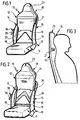
- Figur 1:
- eine schaubildliche Darstellung eines Fahrzeugsitzes mit einer Rückenlehne in unterster Höhenstellung;
- Figur 2:
- eine schaubildliche Darstellung des Fahrzeugsitzes gemäß Figur 1 mit der Rückenlehne in oberster Höhenstellung;
- Figur 3:
- eine schematische Seitenansicht der Rückenlehne mit einer sich abstützenden Person;
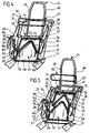
- Figur 4:
- eine schaubildliche Darstellung der Rückenlehne ohne Rückenpolster in unterster Höhenstellung.
- Figur 5:
- eine schaubildliche Darstellung der Rückenlehne ohne Rückenpolster in oberster Höhenstellung;
- Figur 6:
- eine Seitenansicht der Rückenlehne ohne Rückenpolster in unterster Höhenstellung;
- Figur 7:
- eine Seitenansicht der Rückenlehne ohne Rückenpolster in oberster Höhenstellung;
- Figur 8:
- eine Vorderansicht der Rückenlehne ohne Rückenpolster;
- Figur 9:
- eine Schnittansicht längs der Linie 9-9 in Figur 8 in unterster Höhenstellung der Rückenlehne und
- Figur 10:
- eine Schnittansicht längs der Linie 9-9 in Figur 8 in oberster Höhenstellung der Rückenlehne.
Claims (28)
- Rückenlehne für einen Fahrzeugsitz mit zwei Seitenholmen und einer mindestens ein Rückenpolster tragenden Rückenstütze, dadurch gekennzeichnet, daß die Rückenstütze (18) höhenverstellbar ausgestaltet ist.
- Rückenlehne nach Anspruch 1, dadurch gekennzeichnet, daß die Rückenstütze (18) ein unteres, den Beckenbereich einer sitzenden Person abstützendes Stützteil (57) sowie ein oberes, den Schulterbereich der sitzenden Person abstützendes Stützteil (77) umfaßt, wobei das obere Stützteil (77) relativ zum unteren Stützteil (57) höhenverstellbar gehalten ist.
- Rückenlehne nach Anspruch 2, dadurch gekennzeichnet, daß das untere Stützteil (57) und das obere Stützteil (77) höhenverstellbar gehalten sind.
- Rückenlehne nach Anspruch 3, dadurch gekennzeichnet, daß die Rückenlehne (12) eine Verstelleinrichtung (34, 35, 36, 37, 66) umfaßt zum gleichzeitigen Verstellen des oberen Stützteiles (77) und des unteren Stützteiles (57).
- Rückenlehne nach Anspruch 3 oder 4, dadurch gekennzeichnet, daß das obere Stützteil (77) und das untere Stützteil (57) um unterschiedliche Verstellwege verstellbar sind.
- Rückenlehne nach einem der Ansprüche 3 bis 5, dadurch gekennzeichnet, daß die Verstellung des oberen Stützteiles (77) über Getriebemittel (34, 35, 36, 37, 66) mit einer Verstellung des unteren Stützteiles (57) gekoppelt ist.
- Rückenlehne nach einem der Ansprüche 3 bis 6, dadurch gekennzeichnet, daß der Verstellweg des oberen Stützteiles (77) größer ist als der Verstellweg des unteren Stützteiles (57).
- Rückenlehne nach einem der Ansprüche 3 bis 7, dadurch gekennzeichnet, daß der Verstellweg des oberen Stützteiles (77) etwa dreimal so groß ist wie der Verstellweg des unteren Stützteiles (57).
- Rückenlehne nach einem der Ansprüche 2 bis 8, dadurch gekennzeichnet, daß das obere Stützteil (77) ein Schulterstützelement (44) und ein Lendenstützelement (73) umfaßt, wobei das Schulterstützelement (44) relativ zum Lendenstützelement (73) verschwenkbar ist um eine quer zur Längsrichtung der Seitenholme (14, 15) ausgerichtete Schwenkachse.
- Rückenlehne nach Anspruch 9, dadurch gekennzeichnet, daß die Verschwenkbewegung des Schulterstützelementes (44) über Getriebemittel (54, 55) mit der Höhenverstellung der Rückenstütze (18) gekoppelt ist.
- Rückenlehne nach einem der voranstehenden Ansprüche, dadurch gekennzeichnet, daß die Rückenlehne (12) eine integrierte Kopfstütze (23) umfaßt.
- Rückenlehne nach Anspruch 11, dadurch gekennzeichnet, daß die Kopfstütze (23)am Schulterstützelement (44) gehalten ist.
- Rückenlehne nach einem der voranstehenden Ansprüche, dadurch gekennzeichnet, daß die Rückenstütze (18) in Längsrichtung der Seitenholme (14, 15) verschiebbar an den Seitenholmen (14, 15) gehalten ist.
- Rückenlehne nach einem der Ansprüche 2 bis 13, dadurch gekennzeichnet, daß die Seitenholme (14, 15) ein Führungsteil (27, 28) aufweisen, an dem das obere Stützteil (77) und das untere Stützteil (57) in Längsrichtung der Seitenholme (14, 15) verschiebbar gehalten sind.
- Rückenlehne nach Anspruch 14, dadurch gekennzeichnet, daß das Führungsteil eine Kulissenplatte (27, 28) aufweist mit mindestens einer Gleitführung (30, 31), in der ein Kulissenstein (32, 33) verschiebbar ist, an dem das obere Stützteil (77) gehalten ist.
- Rückenlehne nach Anspruch 15, dadurch gekennzeichnet, daß das obere Stützteil (77) unverdrehbar am Kulissenstein (32) fixiert ist.
- Rückenlehne nach Anspruch 15 oder 16, dadurch gekennzeichnet, daß die Gleitführung (30, 31) eine gekrümmte Führungsbahn ausbildet.
- Rückenlehne nach Anspruch 15, 16 oder 17, dadurch gekennzeichnet, daß die Kulissenplatte (27, 28) zwei in Längsrichtung der Seitenholme (14, 15) im Abstand zueinander angeordnete Gleitführungen (30, 31) äufweist, in denen ein Stützrahmen (43) des oberen Stützteiles (77) verschiebbar gehalten ist.
- Rückenlehne nach Anspruch 18, dadurch gekennzeichnet, daß der Stützrahmen (43) das Schulterstützelement (50) sowie ein Trägerteil (44) zur Halterung der Kopfstütze (23) ausbildet.
- Rückenlehne nach Anspruch 18 oder 19, dadurch gekennzeichnet, daß am Stützrahmen (43) das Lendenstützelement (73) gehalten ist.
- Rückenlehne nach Anspruch 20, dadurch gekennzeichnet, daß das Lendenstützelement (73) eine schalenförmige Aufnahme für ein Lendenpolster (20) aufweist.
- Rückenlehne nach einem der Ansprüche 14 bis 21, dadurch gekennzeichnet, daß das untere Stützteil (57) mittels in Langlöcher (62, 63) eingreifender Führungsbolzen (64, 65) am Führungsteil (27, 28) verschiebbar gehalten ist.
- Rückenlehne nach Anspruch 22, dadurch gekennzeichnet, daß die Führungsbolzen (64, 65) am Führungsteil (27, 28) festgelegt sind und in am unteren Stützteil (57) angeordnete Langlöcher (62, 63) eingreifen.
- Rückenlehne nach einem der voranstehenden Ansprüche, dadurch gekennzeichnet, daß die Rückenlehne (12) eine manuell betätigbare Antriebsmechanik (35, 36, 37) zur Höhenverstellung der Rückenstütze (18) aufweist.
- Rückenlehne nach Anspruch 24, dadurch gekennzeichnet, daß die Antriebsmechanik zumindest einen Zahnstangentrieb (34, 35) umfaßt.
- Rückenlehne nach Anspruch 24 oder 25, dadurch gekennzeichnet, daß die Antriebsmechanik zumindest ein Zahnradpaar (35, 37) umfaßt mit zwei auf einer gemeinsamen Antriebswelle (36) unverdrehbar gehaltenen Zahnrädern (35, 37), die jeweils mit einer Zahnstange (34, 66) kämmen, wobei eine der Zahnstangen (34) mit dem oberen Stützteil (77) und die andere Zahnstange (66) mit dem unteren Stützteil (57) gekoppelt ist.
- Rückenlehne nach Anspruch 26, dadurch gekennzeichnet, daß die Antriebsmechanik zwei Zahnradpaare aufweist, die jeweils an einem Seitenholm (14, 15) drehbar gehalten und über Kopplungsglieder (69, 70, 71) miteinander gekoppelt sind.
- Rückenlehne nach Anspruch 27, dadurch gekennzeichnet, daß die Kopplungsglieder eine die beiden Seitenholme (14, 15) miteinander verbindende Kopplungswelle (69) umfassen.
Applications Claiming Priority (2)
| Application Number | Priority Date | Filing Date | Title |
|---|---|---|---|
| DE10111653A DE10111653B4 (de) | 2001-03-12 | 2001-03-12 | Rückenlehne für einen Fahrzeugsitz |
| DE10111653 | 2001-03-12 |
Publications (2)
| Publication Number | Publication Date |
|---|---|
| EP1241047A2 true EP1241047A2 (de) | 2002-09-18 |
| EP1241047A3 EP1241047A3 (de) | 2003-12-17 |
Family
ID=7677049
Family Applications (1)
| Application Number | Title | Priority Date | Filing Date |
|---|---|---|---|
| EP02002655A Withdrawn EP1241047A3 (de) | 2001-03-12 | 2002-02-06 | Rückenlehne für einen Fahrzeugsitz |
Country Status (2)
| Country | Link |
|---|---|
| EP (1) | EP1241047A3 (de) |
| DE (1) | DE10111653B4 (de) |
Cited By (6)
| Publication number | Priority date | Publication date | Assignee | Title |
|---|---|---|---|---|
| EP1400397A3 (de) * | 2002-09-17 | 2005-06-29 | Bertrandt Ingenieurbüro GmbH | Fahrzeugsitz |
| NL1026234C2 (nl) * | 2004-05-19 | 2005-11-22 | Savas Seating B V | Stoel met een elleboogleuning, die zich deels achter de rugleuning uitstrekt. |
| CN103661022A (zh) * | 2013-12-10 | 2014-03-26 | 苏州先锋物流装备科技有限公司 | 一种靠背机构 |
| WO2021043699A1 (de) * | 2019-09-04 | 2021-03-11 | Brose Fahrzeugteile SE & Co. Kommanditgesellschaft, Coburg | Einstellbare nackenstütze |
| CN113194791A (zh) * | 2018-12-10 | 2021-07-30 | 德沃康科技集团有限公司 | 用于座椅家具的腰部支撑装置和具有腰部支撑装置的座椅家具 |
| US12240360B2 (en) * | 2023-02-09 | 2025-03-04 | GM Global Technology Operations LLC | Vertically height adjustable seatback for a vehicle |
Families Citing this family (3)
| Publication number | Priority date | Publication date | Assignee | Title |
|---|---|---|---|---|
| DE102004030319A1 (de) * | 2004-06-23 | 2006-01-12 | Faurecia Autositze Gmbh & Co. Kg | Kopfstützenanordnung für einen Fahrzeugsitz |
| DE102007018424B4 (de) | 2007-04-17 | 2022-08-04 | Bayerische Motoren Werke Aktiengesellschaft | Fahrzeugsitz mit einer Rückenlehne |
| US11447252B2 (en) * | 2019-10-01 | 2022-09-20 | B/E Aerospace, Inc. | Aircraft seat with separated seat back and seat pan |
Family Cites Families (7)
| Publication number | Priority date | Publication date | Assignee | Title |
|---|---|---|---|---|
| DE2706097A1 (de) * | 1977-01-21 | 1978-07-27 | Rolf Scheel | Sitz, insbesondere autositz |
| DE3634500A1 (de) * | 1986-02-10 | 1987-08-20 | Wilfried Prof Dr Me Diebschlag | Sitz, insbesondere autositz |
| DE4238451A1 (de) * | 1992-04-13 | 1993-10-14 | Bayer & Co Gmbh | Sitz mit verstellbarer Rückenlehne |
| FR2714340B1 (fr) * | 1993-12-28 | 1996-03-01 | Bfa | Perfectionnements aux armatures réglables de siège et aux sièges équipés de telles armatures. |
| AU716487B2 (en) * | 1995-09-14 | 2000-02-24 | Autoliv Development Ab | A seat for use in a vehicle |
| US5836647A (en) * | 1997-05-20 | 1998-11-17 | Turman; Ben | Vehicle seat with shock absorption |
| DE19925306C2 (de) * | 1999-06-02 | 2002-11-21 | Faurecia Autositze Gmbh & Co | Rückenlehne eines Kraftfahrzeugsitzes |
-
2001
- 2001-03-12 DE DE10111653A patent/DE10111653B4/de not_active Expired - Fee Related
-
2002
- 2002-02-06 EP EP02002655A patent/EP1241047A3/de not_active Withdrawn
Non-Patent Citations (1)
| Title |
|---|
| None |
Cited By (7)
| Publication number | Priority date | Publication date | Assignee | Title |
|---|---|---|---|---|
| EP1400397A3 (de) * | 2002-09-17 | 2005-06-29 | Bertrandt Ingenieurbüro GmbH | Fahrzeugsitz |
| NL1026234C2 (nl) * | 2004-05-19 | 2005-11-22 | Savas Seating B V | Stoel met een elleboogleuning, die zich deels achter de rugleuning uitstrekt. |
| CN103661022A (zh) * | 2013-12-10 | 2014-03-26 | 苏州先锋物流装备科技有限公司 | 一种靠背机构 |
| CN113194791A (zh) * | 2018-12-10 | 2021-07-30 | 德沃康科技集团有限公司 | 用于座椅家具的腰部支撑装置和具有腰部支撑装置的座椅家具 |
| WO2021043699A1 (de) * | 2019-09-04 | 2021-03-11 | Brose Fahrzeugteile SE & Co. Kommanditgesellschaft, Coburg | Einstellbare nackenstütze |
| US11807144B2 (en) | 2019-09-04 | 2023-11-07 | Brose Fahrzeugtelle SE & Co. Kommanditgesellschaft, Coburg | Adjustable neck support |
| US12240360B2 (en) * | 2023-02-09 | 2025-03-04 | GM Global Technology Operations LLC | Vertically height adjustable seatback for a vehicle |
Also Published As
| Publication number | Publication date |
|---|---|
| EP1241047A3 (de) | 2003-12-17 |
| DE10111653B4 (de) | 2006-12-21 |
| DE10111653A1 (de) | 2002-10-02 |
Similar Documents
| Publication | Publication Date | Title |
|---|---|---|
| DE69304145T2 (de) | Sitz und seine Verwendung in einem Fahrzeug | |
| EP0865960B1 (de) | Fahrzeugsitz | |
| EP0817731B1 (de) | Verstellbare, quer geteilte rückenlehne für einen fahrzeugsitz | |
| DE19646470B4 (de) | Kraftfahrzeugsitz mit einer Lehne und einem Sitz | |
| DE60210583T2 (de) | Fahrzeugsitzanordnung mit einer nockengetriebenen, selbstpositionierenden kopfstütze | |
| DE102009021267B4 (de) | Kopfstütze mit Kopfstützen-Komfortflügeln | |
| DE102004017657B4 (de) | Fahrzeugsitz und Sitzanordnung | |
| DE10111653B4 (de) | Rückenlehne für einen Fahrzeugsitz | |
| DE68906094T2 (de) | Kopfstuetzenelement fuer sitze, insbesondere kraftfahrzeugsitze. | |
| EP1449713B1 (de) | Kopfstütze mit verschiebbarem Kopfstützenauflageteil und Kopfstützen-Komfortflügeln | |
| DE102018108374A1 (de) | Zusammenklappbarer hebemechanismus zur h-punkt-hebung | |
| EP0842814B1 (de) | Kopfstütze für Fahrzeugsitze | |
| DE102006015786B4 (de) | Kopfstützenanordnung für eine Fahrzeugsitzanordnung | |
| DE102007028034B4 (de) | Fahrzeugsitz mit einem schwenkbaren Schulter- und Kopfbereich | |
| WO2000069671A1 (de) | Vorrichtung zum manuellen und/oder automatischen verstellen eines mehrere sitzelemente aufweisenden fahrzeugsitzes | |
| DE10243796B4 (de) | Fahrzeugsitz | |
| DE19914517B4 (de) | Fahrzeugsitz mit einer in ihrer Position einstellbaren Sitznase | |
| EP4480747A1 (de) | Fahrzeugsitz, kraftfahrzeug und verfahren zum betreiben des fahrzeugsitzes | |
| DE10058518B4 (de) | Fahrzeugsitz | |
| DE102005022416B4 (de) | Kopfstütze für einen Fahrzeugsitz | |
| DE10034441A1 (de) | Fahrzeugsitz | |
| DE102004014420A1 (de) | Rohrrahmen für einen Sitz | |
| DE102005035947B4 (de) | Fahrzeugsitz mit einer verformbaren Rückenlehne | |
| DE10347380B4 (de) | Variable Kopfstütze | |
| DE102004003389A1 (de) | Kopfstütze an einem Kraftfahrzeugsitz |
Legal Events
| Date | Code | Title | Description |
|---|---|---|---|
| PUAI | Public reference made under article 153(3) epc to a published international application that has entered the european phase |
Free format text: ORIGINAL CODE: 0009012 |
|
| AK | Designated contracting states |
Kind code of ref document: A2 Designated state(s): AT BE CH CY DE DK ES FI FR GB GR IE IT LI LU MC NL PT SE TR |
|
| AX | Request for extension of the european patent |
Free format text: AL;LT;LV;MK;RO;SI |
|
| PUAL | Search report despatched |
Free format text: ORIGINAL CODE: 0009013 |
|
| AK | Designated contracting states |
Kind code of ref document: A3 Designated state(s): AT BE CH CY DE DK ES FI FR GB GR IE IT LI LU MC NL PT SE TR |
|
| AX | Request for extension of the european patent |
Extension state: AL LT LV MK RO SI |
|
| RIC1 | Information provided on ipc code assigned before grant |
Ipc: 7A 47C 7/38 B Ipc: 7A 47C 7/40 B Ipc: 7B 60N 2/64 B Ipc: 7B 60N 2/42 B Ipc: 7B 60N 2/22 B Ipc: 7B 60N 2/68 A |
|
| AKX | Designation fees paid | ||
| REG | Reference to a national code |
Ref country code: DE Ref legal event code: 8566 |
|
| STAA | Information on the status of an ep patent application or granted ep patent |
Free format text: STATUS: THE APPLICATION IS DEEMED TO BE WITHDRAWN |
|
| 18D | Application deemed to be withdrawn |
Effective date: 20040618 |