EP1239572A2 - Vorrichtung zur berührungslosen Übertragung von Drehbewegungen - Google Patents
Vorrichtung zur berührungslosen Übertragung von Drehbewegungen Download PDFInfo
- Publication number
- EP1239572A2 EP1239572A2 EP02001760A EP02001760A EP1239572A2 EP 1239572 A2 EP1239572 A2 EP 1239572A2 EP 02001760 A EP02001760 A EP 02001760A EP 02001760 A EP02001760 A EP 02001760A EP 1239572 A2 EP1239572 A2 EP 1239572A2
- Authority
- EP
- European Patent Office
- Prior art keywords
- magnets
- magnet
- gap
- magnetic coupling
- magnetic
- Prior art date
- Legal status (The legal status is an assumption and is not a legal conclusion. Google has not performed a legal analysis and makes no representation as to the accuracy of the status listed.)
- Withdrawn
Links
- 230000033001 locomotion Effects 0.000 title claims abstract description 13
- 230000008878 coupling Effects 0.000 claims abstract description 17
- 238000010168 coupling process Methods 0.000 claims abstract description 17
- 238000005859 coupling reaction Methods 0.000 claims abstract description 17
- 230000005540 biological transmission Effects 0.000 claims description 7
- 229910052779 Neodymium Inorganic materials 0.000 claims description 2
- 239000000696 magnetic material Substances 0.000 claims description 2
- QEFYFXOXNSNQGX-UHFFFAOYSA-N neodymium atom Chemical compound [Nd] QEFYFXOXNSNQGX-UHFFFAOYSA-N 0.000 claims description 2
- 238000005516 engineering process Methods 0.000 description 3
- 239000000463 material Substances 0.000 description 3
- 238000002485 combustion reaction Methods 0.000 description 2
- 230000011218 segmentation Effects 0.000 description 2
- 238000004026 adhesive bonding Methods 0.000 description 1
- 238000010276 construction Methods 0.000 description 1
- 239000000498 cooling water Substances 0.000 description 1
- 101150048694 gap2 gene Proteins 0.000 description 1
- 239000007788 liquid Substances 0.000 description 1
- 238000005259 measurement Methods 0.000 description 1
- 238000000034 method Methods 0.000 description 1
Images


Classifications
-
- H—ELECTRICITY
- H02—GENERATION; CONVERSION OR DISTRIBUTION OF ELECTRIC POWER
- H02K—DYNAMO-ELECTRIC MACHINES
- H02K49/00—Dynamo-electric clutches; Dynamo-electric brakes
- H02K49/10—Dynamo-electric clutches; Dynamo-electric brakes of the permanent-magnet type
- H02K49/104—Magnetic couplings consisting of only two coaxial rotary elements, i.e. the driving element and the driven element
- H02K49/108—Magnetic couplings consisting of only two coaxial rotary elements, i.e. the driving element and the driven element with an axial air gap
Definitions
- the invention relates to a device for the contactless transmission of rotary movements according to the preamble of claim 1, wherein under rotary movements rotary drive movements can also be understood.
- DE 198 26 065 A 1 discloses a magnetic coupling for a pipetting device, through which an upper part, which has a piston actuating device, with a Lower part, which has at least one piston-cylinder unit for pipetting liquids has, is releasably connected, making the lower part easily and quickly can be exchanged.
- the magnetic coupling only functions as a holder of the lower part with the upper part.
- DE 198 08 450 A 1 also discloses a magnetic coupling, the one quick-release connection between a tool holder and a drive unit allows.
- the coupling part is inserted by several Cylindrical permanent magnets arranged evenly around the holder axis held axially.
- the rotary drive transmission itself takes place via a shaft held in the tool holder by the magnetic coupling.
- DE 41 104 88 A 1 is a magnetic coupling for a circulation pump for the cooling water of a motor vehicle known, in which the pump wheel on the Magnetic clutch is driven, with a driven magnet within a Pot-shaped housing is arranged and a driving magnet around it pot-shaped housing runs around.
- a device of the generic type can be found in DE 195 42 048 A1.
- the magnetic Coupling is done by a drive side and a drive side Magnetic coupling formed.
- the object of the invention is a device of the generic type Specify type that has a simpler structure.
- the invention is based on the idea of segmenting the device by two To build polarized magnets that face each other and with each other Act.
- the magnets on the ends facing each other are the rotating and / or Means transmitting or receiving rotary drive movements directly appropriate. This can be done by gluing or screwing or a similar procedure is followed.
- the two magnets are only in their front Areas polarized so that a magnetic feedback or a magnetic influence on other components or components behind the magnets is avoided.
- This has the advantage that other components, for example a Sensor technology that can be attached in close proximity to the magnets without that their function is affected. This also enables a compact Construction of the device with other components.
- Another advantage of the inventive idea is that a magnet of the device together with the sensors and other functionally necessary components be housed in a common housing and this can be done as a module. This increases not only the ease of servicing also the ease of repair due to the quick exchangeability of the module.
- the magnets are ring magnets executed and either on the front, facing each other Glued or screwed ends of the shafts.
- the sensors themselves can be used as a potentiometer with a grinder tap, a magnet with a magnetic field sensitive sensor, for example a Hall sensor or Hall switch, etc.
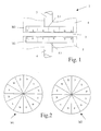
- Figure 1 is the general structure of the inventive device for contactless Transmission of rotary and / or rotary drive movements (rotary movements) shown, which is marked with 1.
- the device 1 has two coupling links in the form of two magnets M 1 and M 2 on each other spaced by a gap 2 and each on one, the rotary movement transmitting / receiving means 3, 4 are attached to the upper end 3.1, 4.1. These ends 3.1, 4.1 face each other.
- the magnets M 1, M 2 have pole segments S, N that alternate. Both magnets are M 1, M 2 aligned with each other in such a way that an N segment of the magnet M 1 lies opposite one another an S segment of the magnet M 2.
- the magnet M 1 can as well the magnet M 2 can each be accommodated in a separate housing 5 or 6.
- FIG. 2 A possible segmentation of the magnets M 1, M 2 from FIG. 1 is shown in FIG. 2 shown, this representation being a top view of the individual magnets M1, M2 from the point of view of the gap2 independently of other variants still to be carried out is.
- the size of the magnets M 1, M 2 and their volume depends on the magnet material and the rotational adjustment force to be used between the magnet M1 and the magnet M2.
- neodymium has a high magnetic energy density, which is advantageous in the case of powerless rotation transmission, so that this material is suitable as a magnetic material.
- the magnets M 1, M 2 can, for example, also be designed as ring magnets with an inner hole.
- gap 2 can only be made so large that it is anyway it is possible that the two magnetic coupling members M 1, M 2 with each other Act.
- FIG. 3 shows a variant from FIG. 1.
- the magnets M 1, M 2 are polarized segmented only in their end region b. As a result, no magnetic field lines emerge in the rear area of the magnets M 1, M 2. Utilizing this advantage, for example, a sensor system 7 can also be located in the immediate vicinity of the magnets M 1, M 2, as also shown in FIG. 4.
- FIG. 4 shows an application of the device 1, here for adjusting a throttle valve 8 of an internal combustion engine, not shown.
- the throttle valve 8 is coupled in a contactless manner via a shaft 9, on which the magnet M 2 of the device 1 is located at the end 9.1 of the device 1, via the magnet M1, the magnet M1 being located at the end 10.1 of the shaft 10 ,
- Flanged on the shaft 10 is, for example, a gearwheel 11 which is driven by a motor 12 for adjusting the throttle valve 8.
- the motor 12 receives a signal for adjusting the throttle valve 8, which is transmitted to the throttle valve 8 without contact via the device 1.
- a magnet 13 of a sensor system 7 mounted on the shaft 10 is also adjusted relative to a sensor 14 of the sensor system 7.
- the adjustment to the required throttle valve position is determined and evaluated in a known manner, in which case, for example, a signal is given to the engine 12 for switching off.
- the sensor system 7 can preferably be attached in close proximity to the magnet M 1, since it does not has magnetic influence and thus on the measurement accuracy of the sensor system 7.
- the driving shaft 10, the gear 11 and the motor 12 as a module 20 manufactured and thus designed to be easily interchangeable.
- a common housing 15 This is then in Port 16 of the throttle valve 8 is used.
- the module 20 itself is not detailed above electrical connections shown with the electronics of the motor vehicle in known way connected.
- the use of the aforementioned device 1 is not limited to that Embodiment throttle valve limited. Rather, the device 1 Use wherever there is a contactless transmission on the front of rotary and / or rotary drive movements.
Landscapes
- Engineering & Computer Science (AREA)
- Power Engineering (AREA)
- Dynamo-Electric Clutches, Dynamo-Electric Brakes (AREA)
- Transmission And Conversion Of Sensor Element Output (AREA)
- Measurement Of Length, Angles, Or The Like Using Electric Or Magnetic Means (AREA)
Abstract
Description
- Figur 1
- eine Darstellung der erfindungsgemäßen Vorrichtung,
- Figur 2
- eine Segmentierung der Magnete aus Figur 1,
- Figur 3
- eine Variante der erfindungsgemäßen Vorrichtung aus Figur 1,
- Figur 4
- ein praktisches Anwendungsbeispiel für die Vorrichtung,
- Figur 5
- einen modulartigen Aufbau der erfindungsgemäßen Vorrichtung.
Die Größe der Magnete M 1, M 2 sowie deren Volumen ist abhängig vom Magnetmaterial und der aufzuwenden Drehverstellkraft zwischen dem Magneten M1 und dem Magneten M2.
Bekanntlich weist Neodym eine hohe magnetische Energiedichte auf, die bei der kraftlosen Drehübertragung von Vorteil ist, so daß sich dieses Material als Magnetmaterial anbietet.
Je leichter die mit dem Magneten M2 zu verdrehende Masse ist, desto geringer kann die Energiedichte im Material oder aber das Volumen des Magneten M1, M2 geringer gewählt werden. In diesen Fällen können die Magnete M 1, M 2 beispielsweise auch als Ringmagnete mit einem Innenloch ausgeführt sein.
Diesen Vorteil nutzend, kann beispielsweise eine Sensorik 7 sich auch in unmittelbarer Nähe der Magnete M 1, M 2 befindet, wie u.a. auch in Figur 4 dargestellt.
Die Drosselklappe 8 ist über eine Welle 9, an der sich am stirnseitigen Ende 9.1 der Magnet M 2 der Vorrichtung 1 befindet, über den Magneten M1 mit einer weiteren Welle 10 berührungslos gekoppelt, wobei sich der Magnet M1 am stirnseitigen Ende 10.1 der Welle 10 befindet. Auf der Welle 10 angeflanscht ist beispielsweise ein Zahnrad 11, welches über einen Motor 12 zur Verstellung der Drosselklappe 8 angetrieben wird.
In bekannter Art und Weise erhält der Motor 12 ein Signal zur Verstellung der Drosselklappe 8, die über die Vorrichtung 1 auf die Drosselklappe 8 berührungslos übertragen wird. Gleichzeitig mit der Drehverstellung der Welle 10 wird ein auf der Welle 10 angebrachter Magnet 13 einer Sensorik 7 gegenüber einem Sensor 14 der Sensorik 7 mit verstellt. Über diese Sensorik 7 wird in bekannter Art und Weise die Verstellung in die geforderte Drosselklappenstellung ermittelt und ausgewertet, wobei in Auswertung dann beispielsweise ein Signal an den Motor 12 zum Abschalten gegeben wird.
Claims (10)
- Vorrichtung zur berührungslosen Übertragung von Drehbewegungen , bestehend aus einer magnetischen Kupplung, welche zwei magnetische Kupplungsglieder aufweist, die durch einen Spalt voneinander mechanisch entkoppelt sind, dadurch gekennzeichnet, daßdie beiden magnetischen Kupplungsglieder zwei segmentiert polarisierte Magnete (M1, M2) sind,die jeweils an den stirnseitigen, zueinander weisenden Ende (3.1, 4.1, 9.1, 10.1) von die Drehbewegung übertragenden / aufnehmenden Mitteln (3, 4, 9, 10) direkt angebracht sind.
- Vorrichtung nach Anspruch 1, dadurch gekennzeichnet, daß die Magnete (M1, M2) im stirnseitigen Bereich (b) polarisiert sind.
- Vorrichtung nach Anspruch 1 oder 2, dadurch gekennzeichnet, daß die Magnete (M1, M2) als Rund- und/oder Ringmagnete ausgeführt sind.
- Vorrichtung nach einem der Ansprüche 1 bis 3, dadurch gekennzeichnet, daß die Mittel (3, 4, 9, 10) Wellen oder Achsen sind.
- Vorrichtung nach einem der Ansprüche 1 bis 4, dadurch gekennzeichnet, daß der Spalt (2) als ein Luftspalt ausgeführt ist.
- Vorrichtung nach einem der Ansprüche 1 bis 5, dadurch gekennzeichnet, daß sich im Spalt (2) Kunststoff befindet.
- Vorrichtung nach einem der Ansprüche 1 bis 6, dadurch gekennzeichnet, daß der Magnetwerkstoff Neodym ist.
- Vorrichtung nach einem der Ansprüche 1 bis 7, dadurch gekennzeichnet, daß zusätzlich eine Sensorik (7) verstellt wird.
- Vorrichtung nach Anspruch 8, dadurch gekennzeichnet, daß die Sensorik (7) aus einem Potentiometer mit Schleiferabgriff oder einem Magnet (13) mit einem von diesem beabstandeten magnetfeldsensitiven Sensor (14) besteht, wobei das Potentiometer bzw. der Magnet (13) an einem der Mittel (9, 10) befestigt sind.
- Vorrichtung nach einem der vorgenannten Ansprüche, dadurch gekennzeichnet, daß die Sensorik (7), die Welle (10), das Zahnrad (11) und der Motor (12) in einem gemeinsamen Gehäuse (15) integriert und als Modul (20) aufgebaut sind.
Applications Claiming Priority (2)
| Application Number | Priority Date | Filing Date | Title |
|---|---|---|---|
| DE10111616 | 2001-03-10 | ||
| DE2001111616 DE10111616A1 (de) | 2001-03-10 | 2001-03-10 | Vorrichtung zur berührungslosen Übertragung von Drehbewegungen |
Publications (2)
| Publication Number | Publication Date |
|---|---|
| EP1239572A2 true EP1239572A2 (de) | 2002-09-11 |
| EP1239572A3 EP1239572A3 (de) | 2004-03-03 |
Family
ID=7677024
Family Applications (1)
| Application Number | Title | Priority Date | Filing Date |
|---|---|---|---|
| EP02001760A Withdrawn EP1239572A3 (de) | 2001-03-10 | 2002-01-25 | Vorrichtung zur berührungslosen Übertragung von Drehbewegungen |
Country Status (2)
| Country | Link |
|---|---|
| EP (1) | EP1239572A3 (de) |
| DE (1) | DE10111616A1 (de) |
Cited By (7)
| Publication number | Priority date | Publication date | Assignee | Title |
|---|---|---|---|---|
| FR2855675A1 (fr) * | 2003-05-26 | 2004-12-03 | Precilec | Frein magnetique et dispositif d'activation comportant un tel frein |
| GB2406000A (en) * | 2003-08-27 | 2005-03-16 | Freepower Ltd | Magnetic coupling for a turbo generator arrangement |
| EP1648079A2 (de) | 2004-10-14 | 2006-04-19 | MARCHESINI GROUP S.p.A. | Bewegungsübertragungsvorrichtung durch ein Trennwand |
| DE102014224151A1 (de) | 2014-11-26 | 2016-06-02 | Mahle International Gmbh | Vorrichtung zur berührungslosen Übertragung von Drehbewegungen |
| DE102015203995A1 (de) | 2015-03-05 | 2016-09-08 | Mahle International Gmbh | Außenrotor einer Vorrichtung zur berührungslosen Übertragung von Drehbewegungen |
| DE102018113950A1 (de) | 2018-06-12 | 2019-12-12 | Geomar Helmholtz-Zentrum Für Ozeanforschung Kiel | Vorrichtung zur berührungslosen Übertragung von Drehbewegungen |
| US11639720B2 (en) | 2017-01-30 | 2023-05-02 | Litens Automotive Partnership | Clutched vacuum pump system |
Families Citing this family (3)
| Publication number | Priority date | Publication date | Assignee | Title |
|---|---|---|---|---|
| TWI266468B (en) * | 2005-10-31 | 2006-11-11 | Sunonwealth Electr Mach Ind Co | Power indirectly linked towing apparatus |
| DE102008016935B4 (de) | 2007-04-04 | 2016-04-14 | Bernhard Brehm | Schnell drehender Elektroantrieb mit ≧12.000 min-1 und 400Hz mit Getriebe verbunden durch eine Magnetkupplung in einem Antriebsgehäuse |
| DE102015211751A1 (de) * | 2015-06-24 | 2016-12-29 | Brose Fahrzeugteile Gmbh & Co. Kg, Hallstadt | Kupplungseinrichtung für eine Antriebsvorrichtung |
Citations (4)
| Publication number | Priority date | Publication date | Assignee | Title |
|---|---|---|---|---|
| DE4110488A1 (de) | 1990-05-15 | 1991-11-21 | Swf Auto Electric Gmbh | Magnetkupplung |
| DE19542048A1 (de) | 1994-11-10 | 1996-05-23 | Fuji Photo Film Co Ltd | Verfahren und Vorrichtung für die Übertragung von Drehantriebskräften an Spindeln |
| DE19808450A1 (de) | 1998-02-27 | 1999-09-02 | Heddernheimer Metallwarenfab | Vorrichtung zum Antreiben eines Werkzeuges |
| DE19826065A1 (de) | 1998-06-12 | 1999-12-16 | Eppendorf Geraetebau Netheler | Pipettiervorrichtung |
Family Cites Families (3)
| Publication number | Priority date | Publication date | Assignee | Title |
|---|---|---|---|---|
| DE2010849A1 (de) * | 1970-03-07 | 1971-09-30 | Mayer J | Unter dem Einfluß magnetischer Induk tion stehender Laufer fur magnetische Getriebe |
| DE3825781A1 (de) * | 1988-07-29 | 1990-02-01 | Bayerische Motoren Werke Ag | Der rueckenlehne eines kraftfahrzeugsitzes zugeordnete armlehne |
| US6084326A (en) * | 1998-02-04 | 2000-07-04 | Smc Kabushiki Kaisha | Actuator |
-
2001
- 2001-03-10 DE DE2001111616 patent/DE10111616A1/de not_active Withdrawn
-
2002
- 2002-01-25 EP EP02001760A patent/EP1239572A3/de not_active Withdrawn
Patent Citations (4)
| Publication number | Priority date | Publication date | Assignee | Title |
|---|---|---|---|---|
| DE4110488A1 (de) | 1990-05-15 | 1991-11-21 | Swf Auto Electric Gmbh | Magnetkupplung |
| DE19542048A1 (de) | 1994-11-10 | 1996-05-23 | Fuji Photo Film Co Ltd | Verfahren und Vorrichtung für die Übertragung von Drehantriebskräften an Spindeln |
| DE19808450A1 (de) | 1998-02-27 | 1999-09-02 | Heddernheimer Metallwarenfab | Vorrichtung zum Antreiben eines Werkzeuges |
| DE19826065A1 (de) | 1998-06-12 | 1999-12-16 | Eppendorf Geraetebau Netheler | Pipettiervorrichtung |
Cited By (10)
| Publication number | Priority date | Publication date | Assignee | Title |
|---|---|---|---|---|
| FR2855675A1 (fr) * | 2003-05-26 | 2004-12-03 | Precilec | Frein magnetique et dispositif d'activation comportant un tel frein |
| GB2406000A (en) * | 2003-08-27 | 2005-03-16 | Freepower Ltd | Magnetic coupling for a turbo generator arrangement |
| GB2406000B (en) * | 2003-08-27 | 2006-12-20 | Freepower Ltd | Working energy recovery system having rotary magnetic coupling |
| EP1648079A2 (de) | 2004-10-14 | 2006-04-19 | MARCHESINI GROUP S.p.A. | Bewegungsübertragungsvorrichtung durch ein Trennwand |
| DE102014224151A1 (de) | 2014-11-26 | 2016-06-02 | Mahle International Gmbh | Vorrichtung zur berührungslosen Übertragung von Drehbewegungen |
| US10361617B2 (en) | 2014-11-26 | 2019-07-23 | Mahle International Gmbh | Magnetic coupling device for transmitting rotational motions without contact |
| DE102015203995A1 (de) | 2015-03-05 | 2016-09-08 | Mahle International Gmbh | Außenrotor einer Vorrichtung zur berührungslosen Übertragung von Drehbewegungen |
| US10411538B2 (en) | 2015-03-05 | 2019-09-10 | Mahle International Gmbh | External rotor of a device for the contactless transmission of rotary movements |
| US11639720B2 (en) | 2017-01-30 | 2023-05-02 | Litens Automotive Partnership | Clutched vacuum pump system |
| DE102018113950A1 (de) | 2018-06-12 | 2019-12-12 | Geomar Helmholtz-Zentrum Für Ozeanforschung Kiel | Vorrichtung zur berührungslosen Übertragung von Drehbewegungen |
Also Published As
| Publication number | Publication date |
|---|---|
| EP1239572A3 (de) | 2004-03-03 |
| DE10111616A1 (de) | 2002-09-12 |
Similar Documents
| Publication | Publication Date | Title |
|---|---|---|
| DE60015827T2 (de) | Drosselklappen-Stellungssensor | |
| DE19635895B4 (de) | Ventilbetätigungsorgan | |
| DE10007968C1 (de) | Mechanische Welle mit integrierter Magnetanordnung | |
| EP0452556B1 (de) | Messwertaufnehmer für eine elektromotorisch angetriebene Servolenkung | |
| DE10111616A1 (de) | Vorrichtung zur berührungslosen Übertragung von Drehbewegungen | |
| DE69619962T2 (de) | Elektrisch gesteuerte drosselklappe mit veränderbarer antriebsübersetzung | |
| EP0712753A2 (de) | Wechselgetriebe für Kraftfahrzeuge mit einer vorn eingebauten, querliegenden Antriebseinheit | |
| EP0445407B1 (de) | Antriebs-Aggregat, insbesondere zum Antrieb eines Fahrzeuges | |
| EP3835626B1 (de) | Wechselgetriebe mit elektromotorisch angetriebener schaltwalze und verfahren zum wechseln zwischen mehreren übersetzungsstufen | |
| EP1312534B1 (de) | Vorrichtung zur Bestimmung des Lenkwinkels eines Lenkrades | |
| DE102015202031A1 (de) | Antriebseinheit für ein Wischersystem | |
| EP1511646A1 (de) | Elektrisch angetriebenes fahrzeug mit einzelradantrieb | |
| EP0148424B1 (de) | Freilaufanordnung für ein gleichachsig gelagertes Zahnradpaar eines Laufwerkes | |
| EP1801338A2 (de) | Getriebemotor | |
| DE10238440C1 (de) | Verstellvorrichtung für einen Kraftfahrzeugsitz | |
| AT523723B1 (de) | Getriebemotor | |
| EP3802010B1 (de) | Antriebsvorrichtung für einen manipulator | |
| EP0650058A1 (de) | Flanschmotor mit Messeinrichtung zur Erfassung der Umdrehung der Motorwelle | |
| EP0875982A1 (de) | Elektromagnetischer Linearantrieb | |
| EP0718961B1 (de) | Elektrischer Impulsmotor | |
| DE10244102A1 (de) | Sensoranordnung zum Erfassen einer umdrehungsbezogenen Grösse eines elektrischen Motors | |
| DE10113436A1 (de) | Vorrichtung zur verstellbaren Positionierung eines Kammeraobjektivs | |
| EP4220094B1 (de) | Vorrichtung zum erfassen von bewegungen und/oder positionen eines magnetischen gegenstandes | |
| DE102022118426B4 (de) | Planetengetriebe | |
| EP1110819B1 (de) | Elektrisch verstellbarer Aussenrückspiegel |
Legal Events
| Date | Code | Title | Description |
|---|---|---|---|
| PUAI | Public reference made under article 153(3) epc to a published international application that has entered the european phase |
Free format text: ORIGINAL CODE: 0009012 |
|
| 17P | Request for examination filed |
Effective date: 20020125 |
|
| AK | Designated contracting states |
Kind code of ref document: A2 Designated state(s): AT BE CH CY DE DK ES FI FR GB GR IE IT LI LU MC NL PT SE TR |
|
| AX | Request for extension of the european patent |
Free format text: AL;LT;LV;MK;RO;SI |
|
| PUAL | Search report despatched |
Free format text: ORIGINAL CODE: 0009013 |
|
| AK | Designated contracting states |
Kind code of ref document: A3 Designated state(s): AT BE CH CY DE DK ES FI FR GB GR IE IT LI LU MC NL PT SE TR |
|
| AX | Request for extension of the european patent |
Extension state: AL LT LV MK RO SI |
|
| AKX | Designation fees paid |
Designated state(s): DE ES FR GB IT |
|
| STAA | Information on the status of an ep patent application or granted ep patent |
Free format text: STATUS: THE APPLICATION HAS BEEN WITHDRAWN |
|
| 18W | Application withdrawn |
Effective date: 20100831 |