EP1239498A1 - Bloc de contacts multipolaire - Google Patents
Bloc de contacts multipolaire Download PDFInfo
- Publication number
- EP1239498A1 EP1239498A1 EP02075931A EP02075931A EP1239498A1 EP 1239498 A1 EP1239498 A1 EP 1239498A1 EP 02075931 A EP02075931 A EP 02075931A EP 02075931 A EP02075931 A EP 02075931A EP 1239498 A1 EP1239498 A1 EP 1239498A1
- Authority
- EP
- European Patent Office
- Prior art keywords
- contact
- plane
- bridges
- parts
- connection
- Prior art date
- Legal status (The legal status is an assumption and is not a legal conclusion. Google has not performed a legal analysis and makes no representation as to the accuracy of the status listed.)
- Granted
Links
- 230000005405 multipole Effects 0.000 title description 2
- 230000006835 compression Effects 0.000 claims description 3
- 238000007906 compression Methods 0.000 claims description 3
- 238000002955 isolation Methods 0.000 claims description 3
- 238000012423 maintenance Methods 0.000 claims description 2
- 239000008188 pellet Substances 0.000 description 2
- 239000011810 insulating material Substances 0.000 description 1
- 230000007935 neutral effect Effects 0.000 description 1
- 238000005192 partition Methods 0.000 description 1
- 230000001681 protective effect Effects 0.000 description 1
- 230000000630 rising effect Effects 0.000 description 1
- 238000006467 substitution reaction Methods 0.000 description 1
- 238000004078 waterproofing Methods 0.000 description 1
Images


Classifications
-
- H—ELECTRICITY
- H01—ELECTRIC ELEMENTS
- H01H—ELECTRIC SWITCHES; RELAYS; SELECTORS; EMERGENCY PROTECTIVE DEVICES
- H01H11/00—Apparatus or processes specially adapted for the manufacture of electric switches
- H01H11/0006—Apparatus or processes specially adapted for the manufacture of electric switches for converting electric switches
- H01H11/0012—Apparatus or processes specially adapted for the manufacture of electric switches for converting electric switches for converting normally open to normally closed switches and vice versa
-
- H—ELECTRICITY
- H01—ELECTRIC ELEMENTS
- H01H—ELECTRIC SWITCHES; RELAYS; SELECTORS; EMERGENCY PROTECTIVE DEVICES
- H01H1/00—Contacts
- H01H1/12—Contacts characterised by the manner in which co-operating contacts engage
- H01H1/14—Contacts characterised by the manner in which co-operating contacts engage by abutting
- H01H1/20—Bridging contacts
-
- H—ELECTRICITY
- H01—ELECTRIC ELEMENTS
- H01H—ELECTRIC SWITCHES; RELAYS; SELECTORS; EMERGENCY PROTECTIVE DEVICES
- H01H9/00—Details of switching devices, not covered by groups H01H1/00 - H01H7/00
- H01H9/0072—Details of switching devices, not covered by groups H01H1/00 - H01H7/00 particular to three-phase switches
Definitions
- the present invention relates to a three-pole contact block, in particular breaking abrupt and positive opening, usable in a movement sensitive switch push button, especially a position switch, push button or the like.
- Such blocks usually include a housing which houses fixed parts of contact terminated at one end by connection pads and bringing to a other end a fixed contact, as well as a mobile equipment provided with several bridges contact so as to provide at least one pole with opening with the fixed contacts and a pole with closure.
- the moving team is requested on the one hand by a pusher, on the other hand by a spring system, the whole being arranged to produce a positive opening and a sudden opening and closing.
- the object of the invention is to allow a multipolar contact block to operate. with at least one switchable pole from the normally open state to the normally state closed or vice versa, without changing the arrangement of the contact carrier.
- connection pads are arranged in at least three separate connection plans, and the moving part has at least three bridges contact distributed so as to cooperate with fixed contacts located in two transverse planes of contact and to move in two frontal planes; of them contact bridges which are located in the foreground foreground cooperate with fixed outgoing contact parts on two connection planes, and the third bridge contact which is located in the second frontal plane cooperates with the fixed parts of outgoing contact on the third connection plane.
- the third connection plan is notably located in the middle position between the first two connection planes.
- the contact block is preferably three-pole and the moving assembly then presents four symmetrically balanced contact bridges, the fourth bridge contact being located in the second frontal plane and not cooperating with the parts fixed contact.
- the moving part may present in substitution for the fourth contact bridge a elastic or movable support piece located in the second frontal plane facing the third contact bridge located in this plane, to move at the same time as the contact bridge located in the same transverse plane.
- contact bridges located at different levels in a same frontal plane are stressed by a single compression spring tending to separate them from each other.
- the mobile assembly is mounted in the case by introduction via an open rear face of the case and a bottom is assembled, in particular snapped into place, to cover the rear face.
- the bottom may then have legs or similar holding elements which take support against fixed contact parts leading to the rear plane to contribute to keep them very simple.
- a terminal isolation cover can be reported, including snapped, on the front of the housing.
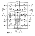
- the three-pole contact block shown in the figures comprises a housing 10 in insulating material which houses six conductive parts 11,12,13,14,15,16 carrying fixed contacts and a moving element 17 with positive opening and sudden movements opening and closing, the crew being guided in this box and equipped with movable contacts which cooperate with the fixed contacts.
- the housing 10 is of quadrangular shape and presents forward three groups of two terminals 21,22,23,24,25,26 distributed on three respective connection planes P1, P2, P3.
- Each terminal 21-26 has a cable clamping screw 27 (or a elastic clamping piece) cooperating with a connection pad 28 of the piece corresponding driver 11-16.
- the associated conductive parts 11, 12 and 15, 16 at terminals 21,22 and 25,26 located in the extreme connection planes P1, P3 are preferably identical to each other; the conductive parts 13.14 associated with the median terminals 23.24 of the median plane P2 differ from the other parts conductive and are preferably identical to each other (see Figure 6).
- the parts 11-16 end by a fixed contact 29 in the form of a pellet; contact pads 29 of the parts 11,12,15,16 are located in a rear frontal plane PR (parallel to the bottom and to the front face of the block and perpendicular to planes P1-P3) and those of parts 13,14 are located in a front plane PF parallel to PR.
- the pellets 29 of the parts 11, 12 are located in a plane P4 intermediate between P1 and P2 and those of parts 15, 16 are located in a plane P5 intermediate between P2 and P3; the pads of the parts 13,14 are located in the plane P4 or P5 depending on the configuration chosen for the block, as will be explained later.
- the housing 10 of the block offers a fixing lug 18, for example to be housed in a position switch body.
- the housing 10 is covered at the front by a cover snap-on 30 which provides a protective and waterproofing function for the terminals.
- the cover 30 has a wall 31 forming the front face of the block while providing access to the screws, as well as inter-terminal isolation partitions 32 and lateral detent notches on the front edges of the block.
- Case 10 presents at the rear an open face 33 which allows the introduction of the contact block and which is closed by a snap-on bottom 34.
- the bottom 34 has a flat wall provided, towards the inside of the block, with lugs 35 which hold the parts fixed rear contact 11,12,13,14. Instead of legs, one can provide shoulders or other similar forms of maintenance.
- the bottom 34 also includes snap tabs 36 on the housing.
- the moving element 17 is capable of generating a positive opening of the contacts. he comprises a pusher 40 movable in a direction Z parallel to the planes PF, PR and biased by a return spring 41, as well as a contact carrier 42 with movement abrupt also movable along Z.
- the contact carrier 42 is mounted movable back and forth on the pusher and is biased by a return piece 43. This piece of reference translates, by means of inversion of movement levers, a movement descending from the moving pusher rising from the contact carrier. Movement amount of contact carrier 42 is made abrupt using two lateral springs 44 at neutral.
- the mechanism described is known and is not the subject of the invention.
- the bridges 45,46 are symmetrically balanced on or in the contact carrier 42 so as to be able to move relative to this one according to Z.
- the planes of symmetry of the bridges are confused with the PF and PR frontal plans.
- the bridges 45,46 are located in the PR plane and the bridges 47.48 in the FP plan; 45.47 bridges on the one hand, and 46.48 bridges on the other hand, are located in two separate planes parallel to P1-P3, so that they can cooperate respectively with parts 11,12 (bridge 45), 15,16 (bridge 46), 13,14 (bridge 47 or bridge 48 depending on the assembly adopted for parts 13,14).
- Each bridge is provided in the middle with an overmolded insulating part 49 which facilitates its guiding in the contact carrier.
- a compression spring 50 is provided which bears directly on the bridges and tends to move them apart from each other to ensure a backlash and good pressure contact, mainly at the time of the changeover.
- an elastic or movable support piece 51 for example an elastic blade, capable of simulating, when the crew mobile 17 is activated, the crushing movement of the bridge to which it is substituted and follow the movement of the rear axle located on the same level.
- the bridges 45,47 form with the corresponding fixed contacts of the poles normally open (NO) and the bridges 46,48 form with the corresponding fixed contacts normally closed poles (NC).
- the described block mounts as follows.
- the fixed contact parts are arranged in the housing 10, then the mobile assembly is inserted from the rear into the housing and the bottom 34 is snapped onto the housing.
- the two configuration possibilities of the block are illustrated in FIGS. 3 and 4.
- the parts 13,14 fixed contact plates are arranged with their contact pads in the plan P4 to form a NO pole.
- the parts 13,14 are arranged with their contact pads in the P5 plane to form a pole NC.
- bridge 47 has been replaced by a part. elastic support for spring 50.
- Parts 13,14 of the NO version can be identical to parts 13,14 of the NC version, so that one passes from a version to the other by simple reversal, or they may be different.
- the housing 10 specific to the NO-NO-NC version of the contact block can be identical to the case specific to the NO-NC-NC version of the block or be different.
Landscapes
- Engineering & Computer Science (AREA)
- Manufacturing & Machinery (AREA)
- Switch Cases, Indication, And Locking (AREA)
- Push-Button Switches (AREA)
Abstract
Description
Claims (8)
- Bloc de contacts multipolaire, notamment à rupture brusque et à ouverture positive, utilisable dans un interrupteur sensible à un mouvement de poussée, particulièrement un interrupteur de position, bouton-poussoir ou organe analogue, comprenant un boítier (10) qui loge des pièces fixes de contact (11-16) terminées à une extrémité par des plages de connexion (28) et portant à une autre extrémité un contact fixe (29), ainsi qu'un équipage mobile (17) sollicité par un poussoir et un système de ressorts et muni de plusieurs ponts de contact de manière à ménager avec les contacts fixes au moins un pôle à ouverture et un pôle à fermeture,
caractérisé par le fait queles plages de connexion (28) sont disposées selon au moins trois plans de connexion distincts (P1-P3), et l'équipage mobile (17) présente au moins trois ponts de contact (45-48) répartis pour prendre contact dans deux plans transversaux de contact (P4,P5) et pour se déplacer dans deux plans frontaux (PF,PR),deux ponts de contact (45,46) situés dans un premier plan frontal (PR) coopèrent avec des pièces fixes de contact (11,12 ;15,16) sortant sur deux plans de connexion (P1,P3),le troisième pont de contact (47,48) situé dans le deuxième plan frontal (PF) coopère avec les pièces fixes de contact (13,14) sortant sur le troisième plan de connexion (P2). - Bloc de contacts selon la revendication 1, caractérisé par le fait que le bloc de contacts est tripolaire et que l'équipage mobile (17) présente quatre ponts de contact (45-48) à disposition symétrique équilibrée, le quatrième pont de contact (48) étant situé dans le deuxième plan frontal et ne coopérant pas avec les pièces de contact fixe.
- Bloc de contacts selon la revendication 1, caractérisé par le fait que l'équipage mobile (17) présente une pièce d'appui élastique ou mobile (51) substituée à un quatrième pont de contact dans le deuxième plan frontal (PF), en regard du troisième pont de contact (48) situé dans ce plan, pour se déplacer en même temps que le pont de contact (45) situé dans le même plan transversal.
- Bloc de contacts selon la revendication 1, caractérisé par le fait que le troisième plan de connexion (P2) est situé en position médiane entre les deux premiers plans de connexion (P1,P2).
- Bloc de contacts selon la revendication 1, caractérisé par le fait que les ponts de contact (45,46 ; 47,48) situés à des niveaux différents dans un même plan frontal sont sollicités par un ressort de compression unique (50) tendant à les écarter l'un de l'autre.
- Bloc de contacts selon la revendication 1, caractérisé par le fait que l'équipage mobile (17) est monté dans le boítier par introduction via une face arrière ouverte (33) du boítier et un fond (34) est assemblé, notamment encliqueté, au boítier pour recouvrir la face arrière.
- Bloc de contacts selon la revendication 6, caractérisé par le fait que le fond (34) présente des pattes (35) ou éléments analogues qui prennent appui contre les pièces fixes de contact (11,12,15,16) aboutissant au plan arrière pour contribuer à leur maintien.
- Bloc de contacts selon la revendication 1, caractérisé par le fait qu'un capot (30) d'isolement des bornes est rapporté, notamment encliqueté, sur la face avant du boítier (10).
Applications Claiming Priority (2)
| Application Number | Priority Date | Filing Date | Title |
|---|---|---|---|
| FR0103278 | 2001-03-09 | ||
| FR0103278A FR2821980B1 (fr) | 2001-03-09 | 2001-03-09 | Bloc de contacts multipolaire |
Publications (2)
| Publication Number | Publication Date |
|---|---|
| EP1239498A1 true EP1239498A1 (fr) | 2002-09-11 |
| EP1239498B1 EP1239498B1 (fr) | 2010-07-07 |
Family
ID=8860966
Family Applications (1)
| Application Number | Title | Priority Date | Filing Date |
|---|---|---|---|
| EP02075931A Expired - Lifetime EP1239498B1 (fr) | 2001-03-09 | 2002-02-22 | Bloc de contacts multipolaire |
Country Status (6)
| Country | Link |
|---|---|
| US (1) | US6657148B2 (fr) |
| EP (1) | EP1239498B1 (fr) |
| CN (1) | CN1237558C (fr) |
| DE (1) | DE60236904D1 (fr) |
| ES (1) | ES2345322T3 (fr) |
| FR (1) | FR2821980B1 (fr) |
Cited By (1)
| Publication number | Priority date | Publication date | Assignee | Title |
|---|---|---|---|---|
| EP1646061A1 (fr) | 2004-10-08 | 2006-04-12 | Pizzato Elettrica S.r.l. | Element de contact modulaire et interrupteur à contact multiple avec un tel element |
Families Citing this family (4)
| Publication number | Priority date | Publication date | Assignee | Title |
|---|---|---|---|---|
| GB0414587D0 (en) * | 2004-06-30 | 2004-08-04 | Eja Ltd | Improvements in or relating to switch contacts |
| US7211758B2 (en) * | 2005-07-12 | 2007-05-01 | Defond Components Limited | Circuit interrupter that produces snap-action connection and disconnection between electrical contacts |
| FR3075458B1 (fr) * | 2017-12-14 | 2020-09-11 | Schneider Electric Ind Sas | Appareil electrique destine a etablir ou interrompre le courant dans un circuit electrique |
| FR3114696B1 (fr) * | 2020-09-25 | 2022-10-14 | Schneider Electric Ind Sas | Bloc empilable pour unité de commande de hauteur réduite |
Citations (5)
| Publication number | Priority date | Publication date | Assignee | Title |
|---|---|---|---|---|
| GB1104218A (en) * | 1965-05-05 | 1968-02-21 | Square D Co | Push button operated electric switch structure |
| US3544929A (en) * | 1969-01-17 | 1970-12-01 | Ite Imperial Corp | Industrial control relay |
| FR2050648A5 (fr) * | 1969-06-19 | 1971-04-02 | Schaltbau Gmbh | |
| WO1996012290A1 (fr) * | 1994-10-13 | 1996-04-25 | Square D Company | Bloc de contact ayant des contacts electriques generalement ouverts ou generalement fermes convertibles |
| US6114639A (en) * | 1998-06-29 | 2000-09-05 | Honeywell International Inc. | Configurable switch |
Family Cites Families (4)
| Publication number | Priority date | Publication date | Assignee | Title |
|---|---|---|---|---|
| DE2848105A1 (de) * | 1978-11-06 | 1980-05-14 | Metzenauer & Jung Gmbh | Schalteranordnung mit wahlweise als oeffner oder schliesser veraenderbaren schalterkontakten |
| US4306123A (en) * | 1979-02-21 | 1981-12-15 | Taylor Glenn R | Contact block |
| US4634820A (en) * | 1983-11-24 | 1987-01-06 | Omron Tateisi Electronics Co. | Quick-break electrical switch with rectilinearly movable plunger actuator |
| US6198058B1 (en) * | 1999-09-27 | 2001-03-06 | Rockwell Technologies, Llc | Switch contact mechanism |
-
2001
- 2001-03-09 FR FR0103278A patent/FR2821980B1/fr not_active Expired - Fee Related
-
2002
- 2002-02-22 ES ES02075931T patent/ES2345322T3/es not_active Expired - Lifetime
- 2002-02-22 EP EP02075931A patent/EP1239498B1/fr not_active Expired - Lifetime
- 2002-02-22 DE DE60236904T patent/DE60236904D1/de not_active Expired - Lifetime
- 2002-02-28 US US10/084,512 patent/US6657148B2/en not_active Expired - Lifetime
- 2002-03-07 CN CNB021067732A patent/CN1237558C/zh not_active Expired - Fee Related
Patent Citations (5)
| Publication number | Priority date | Publication date | Assignee | Title |
|---|---|---|---|---|
| GB1104218A (en) * | 1965-05-05 | 1968-02-21 | Square D Co | Push button operated electric switch structure |
| US3544929A (en) * | 1969-01-17 | 1970-12-01 | Ite Imperial Corp | Industrial control relay |
| FR2050648A5 (fr) * | 1969-06-19 | 1971-04-02 | Schaltbau Gmbh | |
| WO1996012290A1 (fr) * | 1994-10-13 | 1996-04-25 | Square D Company | Bloc de contact ayant des contacts electriques generalement ouverts ou generalement fermes convertibles |
| US6114639A (en) * | 1998-06-29 | 2000-09-05 | Honeywell International Inc. | Configurable switch |
Cited By (1)
| Publication number | Priority date | Publication date | Assignee | Title |
|---|---|---|---|---|
| EP1646061A1 (fr) | 2004-10-08 | 2006-04-12 | Pizzato Elettrica S.r.l. | Element de contact modulaire et interrupteur à contact multiple avec un tel element |
Also Published As
| Publication number | Publication date |
|---|---|
| ES2345322T3 (es) | 2010-09-21 |
| DE60236904D1 (de) | 2010-08-19 |
| US20020125121A1 (en) | 2002-09-12 |
| CN1374670A (zh) | 2002-10-16 |
| CN1237558C (zh) | 2006-01-18 |
| FR2821980A1 (fr) | 2002-09-13 |
| US6657148B2 (en) | 2003-12-02 |
| FR2821980B1 (fr) | 2003-04-25 |
| EP1239498B1 (fr) | 2010-07-07 |
Similar Documents
| Publication | Publication Date | Title |
|---|---|---|
| EP1051718B2 (fr) | Contacteur electromecanique | |
| EP0538149B1 (fr) | Gamme de disjoncteurs basse tension à boitier moulé | |
| EP0647350B1 (fr) | Structure de coupure pour disjoncteur | |
| CN101049841B (zh) | 车辆的手柄开关装置 | |
| FR2753563A1 (fr) | Interrupteur electrique multipolaire ayant un barreau de commutation elementaire par pole | |
| CA2119287A1 (fr) | Coupe-circuit multipolaire modulaire | |
| EP1239498B1 (fr) | Bloc de contacts multipolaire | |
| CA1200265A (fr) | Petit contacteur equipe d'un sous-ensemble d'interrupteurs auxiliaires amovible | |
| EP0208613A1 (fr) | Interrupteur de protection à pôles accouplables | |
| FR2513006A1 (fr) | Dispositif interrupteur modulaire a poles multiples | |
| US6087609A (en) | Circuit breaker, arcing chamber housing for a circuit breaker and housing module for an arcing chamber housing | |
| WO1998024102A1 (fr) | Appareil de coupure tel qu'un commutateur-inverseur pour une installation electrique | |
| EP1256122B1 (fr) | Sous-ensemble de coupure pour appareil interrupteur | |
| EP1053554B1 (fr) | Contacteur electromecanique | |
| EP0511043B1 (fr) | Appareil interrupteur électromécanique à bloc additif retournable | |
| FR2673320A1 (fr) | Appareil interrupteur a commande electromagnetique et a condamnation mecanique. | |
| EP0619592A1 (fr) | Disjoncteur électrique à répulsion électrodynamique des contacts et à chambres de coupure double | |
| FR2397079A1 (fr) | Dispositif pour la fixation d'elements de commutation de circuit electrique sur un tableau de distribution | |
| FR2801722A1 (fr) | Dispositif de coupure pour appareil interrupteur | |
| JPH0810923Y2 (ja) | 多極型回路遮断器 | |
| FR2576141A1 (fr) | Disjoncteur basse tension, avec verrou de maintien agence dans une chambre separee | |
| EP0278850B1 (fr) | Commutateur électrique de structure modulaire | |
| FR2734080A1 (fr) | Appareil interrupteur electrique d'installation | |
| CH636986A5 (fr) | Appareil commutateur comprenant deux interrupteurs electriques loges dans un boitier commun et actionnes par un organe de commande unique. | |
| FR2804242A1 (fr) | Bloc auxiliaire a contact etanche |
Legal Events
| Date | Code | Title | Description |
|---|---|---|---|
| PUAI | Public reference made under article 153(3) epc to a published international application that has entered the european phase |
Free format text: ORIGINAL CODE: 0009012 |
|
| AK | Designated contracting states |
Kind code of ref document: A1 Designated state(s): AT BE CH CY DE DK ES FI FR GB GR IE IT LI LU MC NL PT SE TR |
|
| AX | Request for extension of the european patent |
Free format text: AL;LT;LV;MK;RO;SI |
|
| 17P | Request for examination filed |
Effective date: 20021001 |
|
| AKX | Designation fees paid |
Designated state(s): DE ES IT |
|
| RAP1 | Party data changed (applicant data changed or rights of an application transferred) |
Owner name: SCHNEIDER ELECTRIC INDUSTRIES SAS |
|
| 17Q | First examination report despatched |
Effective date: 20090610 |
|
| GRAP | Despatch of communication of intention to grant a patent |
Free format text: ORIGINAL CODE: EPIDOSNIGR1 |
|
| GRAS | Grant fee paid |
Free format text: ORIGINAL CODE: EPIDOSNIGR3 |
|
| GRAA | (expected) grant |
Free format text: ORIGINAL CODE: 0009210 |
|
| AK | Designated contracting states |
Kind code of ref document: B1 Designated state(s): DE ES IT |
|
| REF | Corresponds to: |
Ref document number: 60236904 Country of ref document: DE Date of ref document: 20100819 Kind code of ref document: P |
|
| REG | Reference to a national code |
Ref country code: ES Ref legal event code: FG2A Ref document number: 2345322 Country of ref document: ES Kind code of ref document: T3 |
|
| PLBE | No opposition filed within time limit |
Free format text: ORIGINAL CODE: 0009261 |
|
| STAA | Information on the status of an ep patent application or granted ep patent |
Free format text: STATUS: NO OPPOSITION FILED WITHIN TIME LIMIT |
|
| 26N | No opposition filed |
Effective date: 20110408 |
|
| REG | Reference to a national code |
Ref country code: DE Ref legal event code: R097 Ref document number: 60236904 Country of ref document: DE Effective date: 20110408 |
|
| PGFP | Annual fee paid to national office [announced via postgrant information from national office to epo] |
Ref country code: ES Payment date: 20160301 Year of fee payment: 15 Ref country code: IT Payment date: 20160215 Year of fee payment: 15 Ref country code: DE Payment date: 20160113 Year of fee payment: 15 |
|
| REG | Reference to a national code |
Ref country code: DE Ref legal event code: R119 Ref document number: 60236904 Country of ref document: DE |
|
| PG25 | Lapsed in a contracting state [announced via postgrant information from national office to epo] |
Ref country code: DE Free format text: LAPSE BECAUSE OF NON-PAYMENT OF DUE FEES Effective date: 20170901 |
|
| PG25 | Lapsed in a contracting state [announced via postgrant information from national office to epo] |
Ref country code: IT Free format text: LAPSE BECAUSE OF NON-PAYMENT OF DUE FEES Effective date: 20170222 |
|
| REG | Reference to a national code |
Ref country code: ES Ref legal event code: FD2A Effective date: 20180704 |
|
| PG25 | Lapsed in a contracting state [announced via postgrant information from national office to epo] |
Ref country code: ES Free format text: LAPSE BECAUSE OF NON-PAYMENT OF DUE FEES Effective date: 20170223 |