EP1239124A2 - Schaltbarer Stössel zur direkten Übertragung eines Nockenhubes auf eine Stösselstange - Google Patents
Schaltbarer Stössel zur direkten Übertragung eines Nockenhubes auf eine Stösselstange Download PDFInfo
- Publication number
- EP1239124A2 EP1239124A2 EP02001305A EP02001305A EP1239124A2 EP 1239124 A2 EP1239124 A2 EP 1239124A2 EP 02001305 A EP02001305 A EP 02001305A EP 02001305 A EP02001305 A EP 02001305A EP 1239124 A2 EP1239124 A2 EP 1239124A2
- Authority
- EP
- European Patent Office
- Prior art keywords
- housing
- inner element
- pressure piston
- recess
- compression spring
- Prior art date
- Legal status (The legal status is an assumption and is not a legal conclusion. Google has not performed a legal analysis and makes no representation as to the accuracy of the status listed.)
- Granted
Links
Images
Classifications
-
- F—MECHANICAL ENGINEERING; LIGHTING; HEATING; WEAPONS; BLASTING
- F01—MACHINES OR ENGINES IN GENERAL; ENGINE PLANTS IN GENERAL; STEAM ENGINES
- F01L—CYCLICALLY OPERATING VALVES FOR MACHINES OR ENGINES
- F01L1/00—Valve-gear or valve arrangements, e.g. lift-valve gear
- F01L1/12—Transmitting gear between valve drive and valve
- F01L1/14—Tappets; Push rods
- F01L1/146—Push-rods
-
- F—MECHANICAL ENGINEERING; LIGHTING; HEATING; WEAPONS; BLASTING
- F01—MACHINES OR ENGINES IN GENERAL; ENGINE PLANTS IN GENERAL; STEAM ENGINES
- F01L—CYCLICALLY OPERATING VALVES FOR MACHINES OR ENGINES
- F01L13/00—Modifications of valve-gear to facilitate reversing, braking, starting, changing compression ratio, or other specific operations
- F01L13/0005—Deactivating valves
-
- F—MECHANICAL ENGINEERING; LIGHTING; HEATING; WEAPONS; BLASTING
- F01—MACHINES OR ENGINES IN GENERAL; ENGINE PLANTS IN GENERAL; STEAM ENGINES
- F01L—CYCLICALLY OPERATING VALVES FOR MACHINES OR ENGINES
- F01L13/00—Modifications of valve-gear to facilitate reversing, braking, starting, changing compression ratio, or other specific operations
- F01L13/0015—Modifications of valve-gear to facilitate reversing, braking, starting, changing compression ratio, or other specific operations for optimising engine performances by modifying valve lift according to various working parameters, e.g. rotational speed, load, torque
- F01L13/0031—Modifications of valve-gear to facilitate reversing, braking, starting, changing compression ratio, or other specific operations for optimising engine performances by modifying valve lift according to various working parameters, e.g. rotational speed, load, torque by modification of tappet or pushrod length
-
- F—MECHANICAL ENGINEERING; LIGHTING; HEATING; WEAPONS; BLASTING
- F01—MACHINES OR ENGINES IN GENERAL; ENGINE PLANTS IN GENERAL; STEAM ENGINES
- F01L—CYCLICALLY OPERATING VALVES FOR MACHINES OR ENGINES
- F01L2305/00—Valve arrangements comprising rollers
Definitions
- the invention relates to a switchable plunger for the direct transmission of a Cam stroke on a push rod, especially in a valve train
- Internal combustion engine with a housing, in the axially extending recess a longitudinally movable inner element is arranged, which is in a relative position connectable to the housing via coupling means at least indirectly with the latter is, the housing on one side facing away from the recess a contact surface for a cam and the inner element on the side of the Recess has a system for the push rod and away from the housing at least one helical compression spring is acted upon and in the plunger hydraulic lash adjuster with a pressure piston is installed, which has a high-pressure chamber on one end and a one on its outer jacket Leakage gap and limited with its bore a reservoir for hydraulic fluid.
- Such a plunger is based on the one considered to be generic DE 198 44 202.
- a pressure piston of a hydraulic lash adjuster in one Inner element which in turn runs in a housing, is a leakage gap from a high-pressure chamber axially below the pressure piston, which only is insufficiently large because it has a relatively small diameter. Thereby the ram has insufficient hydraulic rigidity.
- Second is determine that due to the internal arrangement of a compression spring, also called lost motion spring, the overall length of the plunger housing is enlarged unnecessarily. Thus, a plunger is undesirably large Mass before.
- the object of the invention is therefore to provide a plunger of the type described above create, in which the disadvantages cited are eliminated with simple means.
- this object is achieved in that the pressure piston is built directly into the recess of the housing and immediately between its front side and the closed, facing side of the Housing of the high-pressure chamber is formed, the inner element directly in the bore of the pressure piston runs.
- the tappet thus has a significantly improved hydraulic rigidity.
- a helical compression spring assembly By moving the helical compression spring outside the housing, a helical compression spring assembly is also conceivable, this can be in its Height can be minimized. This makes it possible to use relatively heavy housing sections to be replaced by thin-walled components (attachment of the inner element).
- another helical compression spring or another spring element can be arranged, which supports the first mentioned helical compression spring acts. If necessary, only one of the helical compression springs mentioned are used.
- Sliders can be used as coupling means, which according to an expedient Embodiment of the invention in a radial web of the inner element are positioned and radially outwards (in the coupling direction) via compression spring force and radially inwards (in the decoupling direction) via hydraulic medium pressure can be relocated.
- This radial web limits in a simple manner and with its underside at the same time one enclosed by the pressure piston Storage room for the hydraulic medium in the direction of the high pressure room path.
- a simple measure for supplying hydraulic fluid to the play compensation element is the subject of subclaim 4.
- the inner element also for lightweight reasons, hollow cylindrical, wherein in The flow direction seen the system for the push rod in the inner element at least has an opening through which the hydraulic fluid is supplied can. Furthermore, there is between one flank of the radial web and one Inner jacket of the inner element formed at least one passage through which the hydraulic fluid around the coupling means further into the reservoir, the is largely enclosed by the pressure piston, can be supplied.
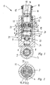
- Figure 1 discloses a switchable plunger 1 for the direct transmission of a Cam stroke on a push rod. This can be switched or switched off designed. It consists of a housing 2, in the recess 3 Pressure piston 4 runs with its outer jacket 5. Between the recess 3 and a leakage gap for hydraulic medium is formed in the outer jacket 5.
- One side 6 of the housing 2 facing away from the recess 3 is closed formed and has a contact surface 7 for a cam.
- the contact area 7 is designed as a roller, which is supported by a roller bearing 8 on a pin 9 is led.
- the bolt 9 is in turn mounted on the end face in the housing 2.
- a mouth of the recess 3, which faces away from the side 6, is from towers over an approach 10.
- This is thin-walled and hollow-cylindrical and connected in one piece to an inner element 11.
- Conceivable and provided is however also a two-part training, in which the approach 10 as mentioned via a clip connection with the inner element, for example 11 is coupled.
- the inner element 11 runs in a bore 12 of the aforementioned pressure piston 4 relatively axially movable to this. It has a Appendix 13 for a push rod, not shown, with an opening 14 for supplying hydraulic fluid into the plunger interior.
- the Inner element 11 with an end stop / a path limitation in the distance from the housing Direction is provided. This prevents the components from falling apart or can an exact location assignment of the coupling means mentioned later 19 to be created 21.
- Radial are conceivable protruding means such as pins, rings, tongue and groove connections and. ⁇ ., The communicate for example at the edge with the housing 2 or pressure piston 4.
- FIG. 1 the person skilled in the art can see in FIG. 1 that the approach 10 is enclosed by a helical compression spring 15. This is at one end mounted on a support 16 facing away from the side 6 and on the other At the end it lies on an edge 17 of the pressure piston 4.
- the inner element has in its area lying within the pressure piston 4 11 a radial web 18.
- Piston arranged as a coupling means 19. These are radially outward acted upon by the force of a spring means 20.
- the coupling means 19 run in sections in a corresponding one Recording 21 on the pressure piston 4.
- a displacement of the coupling means 19 relative radially inward for a decoupling purpose of the inner element 11 to the housing 2 is realized via hydraulic medium, which is in front of the end faces 22 the coupling means 19 can be passed.
- the arrangement of the helical compression spring 15 around the Approach 10 around the housing 2 can be shortened, which is the total mass of the Ram 1 advantageously reduced.
- the pressure piston 4 closes a storage space 25 above its end face 23 for hydraulic fluid. This is axially upwards through a bottom of the Radialsteges 18 limited. It can be seen that in the storage room 25 a further helical compression spring 26 is arranged. This supports the effect the helical compression spring 15. If necessary, the helical compression spring 26 can be dispensed with. Furthermore, there is a transverse one in the storage space 25 Bridge 27 indicated in the drawing. Below this, the one with at least is provided a passage for the hydraulic medium, that is ultimately Hydraulic fluid accumulated. The inner element 11 can thus be uncoupled State of the housing 2 no longer undesirably pan in the storage room 25. The bridge 27 is arranged so that it is during the immersion movement of the inner element 11 is not touched by this.
- FIG. 2 An unimpeded supply line to the opening 14 of the system 13 hydraulic fluid present to the reservoir 25 is ensured that the radial web 18 has a passage 29 in the region of its flanks 28 has, which is limited by the inner jacket 30 of the inner member 11.
- a common supply of the hydraulic is also conceivable Play compensation elements 31 in the plunger 1 and the coupling means 19.
Landscapes
- Engineering & Computer Science (AREA)
- Mechanical Engineering (AREA)
- General Engineering & Computer Science (AREA)
- Valve-Gear Or Valve Arrangements (AREA)
- Actuator (AREA)
- Valve Device For Special Equipments (AREA)
Abstract
Description
- Figur 1
- einen Längsschnitt durch einen erfindungsgemäßen Stößel und
- Figur 2
- eine Schnittansicht durch die Koppelmittel des Stößel entlang der Schnittlinie A-A der Figur 1.
- 1
- Stößel
- 2
- Gehäuse
- 3
- Aussparung
- 4
- Druckkolben
- 5
- Außenmantel
- 6
- Seite
- 7
- Anlauffläche
- 8
- Wälzlagerung
- 9
- Bolzen
- 10
- Ansatz
- 11
- Innenelement
- 12
- Bohrung
- 13
- Anlage
- 14
- Öffnung
- 15
- Schraubendruckfeder
- 16
- Abstützung
- 17
- Rand
- 18
- Radialsteg
- 19
- Koppelmittel
- 20
- Federmittel
- 21
- Aufnahme
- 22
- Stirnseite
- 23
- Stirnseite
- 24
- Hochdruckraum
- 25
- Vorratsraum
- 26
- Schraubendruckfeder
- 27
- Brücke
- 28
- Flanke
- 29
- Durchlaß
- 30
- Innenmantel
- 31
- hydraulisches Spielausgleichselement
Claims (8)
- Schaltbarer Stößel (1) zur direkten Übertragung eines Nockenhubes auf eine Stößelstange, insbesondere in einem Ventiltrieb einer Brennkraftmaschine, mit einem Gehäuse (2), in dessen axial verlaufender Aussparung (3) ein längsbewegliches Innenelement (11) angeordnet ist, das in einer Relativstellung zum Gehäuse (2) über Koppelmittel (19) zumindest mittelbar mit diesem verbindbar ist, wobei an einer der Aussparung (3) abgewandten Seite (6) das Gehäuse (2) eine Anlauffläche (7) für einen Nocken und das Innenelement (11) an der Seite der Aussparung (3) eine Anlage (13) für die Stößelstange hat und vom Gehäuse (2) weg durch wenigstens eine Schraubendruckfeder (15, 26) beaufschlagt ist und wobei im Stößel (1) ein hydraulisches Spielausgleichselement (31) mit einem Druckkolben (4) eingebaut ist, der an einer Stirnseite (23) einen Hochdruckraum (24), an seinem Außenmantel (5) einen Leckspalt sowie mit seiner Bohrung (12) einen Vorratsraum (25) für Hydraulikmittel begrenzt, dadurch gekennzeichnet,dass der Druckkolben (4) direkt in die Aussparung (3) des Gehäuses (2) eingebaut ist und unmittelbar zwischen seiner Stirnseite (23) sowie der geschlossen ausgebildeten, abgewandten Seite (6) des Gehäuses (2) der Hochdruckraum (24) gebildet ist, wobei das Innenelement (11) direkt in der Bohrung (12) des Druckkolbens (4) verläuft.
- Stößel nach Anspruch 1 oder nach dem Oberbegriff des Anspruchs 1, dadurch gekennzeichnet,dass das Innenelement (11) mit einem Ansatz (10) die Aussparung (3) des Gehäuses (2) überragt, wobei eine Schraubendruckfeder (15) zumindest größtenteils um den Ansatz (10) gelegt ist und einenends gegen eine der Aussparung (3) abgewandte Abstützung (16) des Ansatzes (10) und anderenends gegen einen Rand (17) bzw. randnahen Abschnitt des Druckkolbens (4) oder Gehäuses (2) wirkt bzw. gegenüber dem Gehäuse (2) sich abstützt.
- Stößel nach Anspruch 1, dadurch gekennzeichnet,dass die Koppelmittel (19) als wenigstens ein Schieber ausgebildet sind, der im entkoppelten Zustand des Innenelements (11) vom Gehäuse (2) in einem Radialsteg (18) des Innenelements (11) verläuft und für den Koppelzustand abschnittsweise in eine radial außen vorgelagerte Aufnahme (21) des Druckkolbens (4) verlagerbar ist.
- Stößel nach Anspruch 3, dadurch gekennzeichnet,dass das Innenelement (11) hohlzylindrisch ist, wobei es wenigstens einen axial verlaufenden Durchlaß (29) für Hydraulikmittel hat, der radial zwischen einer Flanke (28) des Radialsteges (18) und einem Innenmantel (30) des Innenelements (11) gebildet ist und eingangsseitig mit einer Öffnung (14) in der Anlage (13) kommuniziert und ausgangsseitig zu dem Vorratsraum (25) im Druckkolben (4) führt, welcher in Richtung von der Stirnseite (23) des Druckkolbens (4) weg von dem Radialsteg (18) begrenzt ist.
- Stößel nach Anspruch 4, dadurch gekennzeichnet,dass der Vorratsraum (25) in Richtung zum Radialsteg (18) durch eine dünnwandige Brücke (27) mit wenigstens einer Öffnung begrenzt ist.
- Stößel nach Anspruch 2, dadurch gekennzeichnet,dass eine Schraubendruckfeder (26) in den Vorratsraum (25) eingebaut ist, die einerseits an der Stirnseite (23) des Druckkolbens (4) anliegt und andererseits auf das Innenelement (11) einwirkt.
- Stößel nach Anspruch 2, dadurch gekennzeichnet,dass der Ansatz (10) aus dünnwandigem Leichtbauwerkstoff wie Blech besteht.
- Stößel nach Anspruch 1, dadurch gekennzeichnet,dass die Anlauffläche (7) für den Nocken als drehbare Rolle hergestellt ist, die auf einem Bolzen (9) gegenüber dem Gehäuse (2) gelagert ist.
Applications Claiming Priority (2)
| Application Number | Priority Date | Filing Date | Title |
|---|---|---|---|
| DE10111511 | 2001-03-09 | ||
| DE10111511A DE10111511A1 (de) | 2001-03-09 | 2001-03-09 | Schaltbarer Stößel zur direkten Übertragung eines Nockenhubes auf eine Stößelstange |
Publications (3)
| Publication Number | Publication Date |
|---|---|
| EP1239124A2 true EP1239124A2 (de) | 2002-09-11 |
| EP1239124A3 EP1239124A3 (de) | 2003-01-08 |
| EP1239124B1 EP1239124B1 (de) | 2003-12-03 |
Family
ID=7676950
Family Applications (1)
| Application Number | Title | Priority Date | Filing Date |
|---|---|---|---|
| EP02001305A Expired - Lifetime EP1239124B1 (de) | 2001-03-09 | 2002-01-18 | Schaltbarer Stössel zur direkten Übertragung eines Nockenhubes auf eine Stösselstange |
Country Status (3)
| Country | Link |
|---|---|
| EP (1) | EP1239124B1 (de) |
| DE (2) | DE10111511A1 (de) |
| ES (1) | ES2211832T3 (de) |
Families Citing this family (1)
| Publication number | Priority date | Publication date | Assignee | Title |
|---|---|---|---|---|
| US11187119B2 (en) | 2019-09-16 | 2021-11-30 | Eaton Intelligent Power Limited | Latch pin for use in valve lifter and valve lifter |
Family Cites Families (9)
| Publication number | Priority date | Publication date | Assignee | Title |
|---|---|---|---|---|
| GB574852A (en) * | 1943-03-10 | 1946-01-23 | Gen Motors Corp | Improved hydraulic valve tappet for internal combustion engines |
| DE950515C (de) * | 1954-02-18 | 1956-10-11 | Maschf Augsburg Nuernberg Ag | Hydraulische Spielausgleichsvorrichtung |
| US2887996A (en) * | 1957-10-28 | 1959-05-26 | Wood George | Hydraulic lash adjusters |
| US2942595A (en) * | 1958-04-09 | 1960-06-28 | Johnson Products Inc | Hydraulic tappet |
| US5361733A (en) * | 1993-01-28 | 1994-11-08 | General Motors Corporation | Compact valve lifters |
| DE4442057B4 (de) * | 1994-11-25 | 2005-07-28 | Ina-Schaeffler Kg | Hydraulische Spielausgleichsvorrichtung |
| DE19844202A1 (de) * | 1998-09-26 | 2000-03-30 | Schaeffler Waelzlager Ohg | Schaltbarer Nockenfolger |
| DE19947848A1 (de) * | 1998-10-28 | 2000-05-04 | Fev Motorentech Gmbh | Aktuator zur Betätigung eines Stellgliedes, insbesondere eines Gaswechselventils mit einseitiger Federanordnung |
| US6196175B1 (en) * | 1999-02-23 | 2001-03-06 | Eaton Corporation | Hydraulically actuated valve deactivating roller follower |
-
2001
- 2001-03-09 DE DE10111511A patent/DE10111511A1/de not_active Withdrawn
-
2002
- 2002-01-18 ES ES02001305T patent/ES2211832T3/es not_active Expired - Lifetime
- 2002-01-18 DE DE50200120T patent/DE50200120D1/de not_active Expired - Lifetime
- 2002-01-18 EP EP02001305A patent/EP1239124B1/de not_active Expired - Lifetime
Also Published As
| Publication number | Publication date |
|---|---|
| DE50200120D1 (de) | 2004-01-15 |
| DE10111511A1 (de) | 2002-10-24 |
| EP1239124B1 (de) | 2003-12-03 |
| ES2211832T3 (es) | 2004-07-16 |
| EP1239124A3 (de) | 2003-01-08 |
Similar Documents
| Publication | Publication Date | Title |
|---|---|---|
| DE4499784B4 (de) | Abstützelement | |
| DE19915531A1 (de) | Nockenfolger oder Abstützelement für einen Nockenfolger eines Ventiltriebs einer Brennkraftmaschine | |
| DE102008057830A1 (de) | Abschaltbarer Stößel | |
| DE19915532B4 (de) | Schaltbares Ventiltriebsglied | |
| DE102007051453A1 (de) | Schaltbarer Doppelstößel | |
| WO2008110440A1 (de) | Schaltbares abstützelement für einen ventiltrieb einer brennkraftmaschine | |
| DE10002287A1 (de) | Schaltbarer Flach- oder Rollenstössel | |
| DE19681239B4 (de) | Stößel für den Ventiltrieb einer Brennkraftmaschine | |
| EP0623190B1 (de) | Stössel mit hydraulischem ventilspielausgleich und leerhubkolben | |
| DE10109954A1 (de) | Ventiltrieb einer Brennkraftmaschine | |
| EP1881165A2 (de) | Schaltbarer Ventiltrieb für eine Brennkraftmaschine | |
| DE102004028033B4 (de) | Kipphebelachse | |
| EP1881166A1 (de) | Schaltbarer Ventiltrieb für eine Brennkraftmaschine | |
| DE19914046A1 (de) | Als Kipp- oder Schwinghebel ausgebildeter Nockenfolger eines Ventiltriebs einer Brennkraftmaschine | |
| DE10204673A1 (de) | Schaltelement für einen Ventiltrieb einer Brennkraftmaschine | |
| DE102005003611A1 (de) | Ventiltrieb einer Brennkraftmaschine | |
| DE4442057B4 (de) | Hydraulische Spielausgleichsvorrichtung | |
| DE102005030718A1 (de) | Abschaltelement für einen Ventiltrieb einer Brennkraftmaschine | |
| DE19942983B4 (de) | Hydraulisches Spielausgleichselement | |
| DE19914044A1 (de) | In einen Zylinderkopf eines Ventiltriebs einer Brennkraftmaschine eingebauter Kipphebel | |
| DE102010027608A1 (de) | Steuertrieb einer Brennkraftmaschine | |
| EP1239124B1 (de) | Schaltbarer Stössel zur direkten Übertragung eines Nockenhubes auf eine Stösselstange | |
| DE102006007375A1 (de) | Hydraulisches Abstützelement | |
| DE19952909A1 (de) | Schaltbares Abstützelement | |
| DE19818146A1 (de) | Ventiltrieb einer Brennkraftmaschine |
Legal Events
| Date | Code | Title | Description |
|---|---|---|---|
| PUAI | Public reference made under article 153(3) epc to a published international application that has entered the european phase |
Free format text: ORIGINAL CODE: 0009012 |
|
| 17P | Request for examination filed |
Effective date: 20020118 |
|
| AK | Designated contracting states |
Kind code of ref document: A2 Designated state(s): AT BE CH CY DE DK ES FI FR GB GR IE IT LI LU MC NL PT SE TR |
|
| AX | Request for extension of the european patent |
Free format text: AL;LT;LV;MK;RO;SI |
|
| PUAL | Search report despatched |
Free format text: ORIGINAL CODE: 0009013 |
|
| AK | Designated contracting states |
Kind code of ref document: A3 Designated state(s): AT BE CH CY DE DK ES FI FR GB GR IE IT LI LU MC NL PT SE TR |
|
| AX | Request for extension of the european patent |
Free format text: AL;LT;LV;MK;RO;SI |
|
| RIC1 | Information provided on ipc code assigned before grant |
Free format text: 7F 01L 13/00 A, 7F 01L 1/14 B, 7F 01L 1/24 B |
|
| 17Q | First examination report despatched |
Effective date: 20030221 |
|
| GRAH | Despatch of communication of intention to grant a patent |
Free format text: ORIGINAL CODE: EPIDOS IGRA |
|
| GRAS | Grant fee paid |
Free format text: ORIGINAL CODE: EPIDOSNIGR3 |
|
| AKX | Designation fees paid |
Designated state(s): DE ES FR GB IT SE |
|
| GRAA | (expected) grant |
Free format text: ORIGINAL CODE: 0009210 |
|
| AK | Designated contracting states |
Kind code of ref document: B1 Designated state(s): DE ES FR GB IT SE |
|
| REG | Reference to a national code |
Ref country code: GB Ref legal event code: FG4D Free format text: NOT ENGLISH |
|
| REG | Reference to a national code |
Ref country code: SE Ref legal event code: TRGR |
|
| REG | Reference to a national code |
Ref country code: IE Ref legal event code: FG4D Free format text: GERMAN |
|
| REF | Corresponds to: |
Ref document number: 50200120 Country of ref document: DE Date of ref document: 20040115 Kind code of ref document: P |
|
| GBT | Gb: translation of ep patent filed (gb section 77(6)(a)/1977) |
Effective date: 20040315 |
|
| REG | Reference to a national code |
Ref country code: ES Ref legal event code: FG2A Ref document number: 2211832 Country of ref document: ES Kind code of ref document: T3 |
|
| REG | Reference to a national code |
Ref country code: IE Ref legal event code: FD4D |
|
| ET | Fr: translation filed | ||
| PLBE | No opposition filed within time limit |
Free format text: ORIGINAL CODE: 0009261 |
|
| STAA | Information on the status of an ep patent application or granted ep patent |
Free format text: STATUS: NO OPPOSITION FILED WITHIN TIME LIMIT |
|
| 26N | No opposition filed |
Effective date: 20040906 |
|
| PGFP | Annual fee paid to national office [announced via postgrant information from national office to epo] |
Ref country code: SE Payment date: 20050107 Year of fee payment: 4 |
|
| PGFP | Annual fee paid to national office [announced via postgrant information from national office to epo] |
Ref country code: FR Payment date: 20050110 Year of fee payment: 4 |
|
| PGFP | Annual fee paid to national office [announced via postgrant information from national office to epo] |
Ref country code: ES Payment date: 20050211 Year of fee payment: 4 |
|
| PG25 | Lapsed in a contracting state [announced via postgrant information from national office to epo] |
Ref country code: GB Free format text: LAPSE BECAUSE OF NON-PAYMENT OF DUE FEES Effective date: 20060118 |
|
| PG25 | Lapsed in a contracting state [announced via postgrant information from national office to epo] |
Ref country code: ES Free format text: LAPSE BECAUSE OF NON-PAYMENT OF DUE FEES Effective date: 20060119 Ref country code: SE Free format text: LAPSE BECAUSE OF NON-PAYMENT OF DUE FEES Effective date: 20060119 |
|
| PG25 | Lapsed in a contracting state [announced via postgrant information from national office to epo] |
Ref country code: FR Free format text: LAPSE BECAUSE OF NON-PAYMENT OF DUE FEES Effective date: 20060131 |
|
| PGFP | Annual fee paid to national office [announced via postgrant information from national office to epo] |
Ref country code: IT Payment date: 20060131 Year of fee payment: 5 |
|
| EUG | Se: european patent has lapsed | ||
| GBPC | Gb: european patent ceased through non-payment of renewal fee |
Effective date: 20060118 |
|
| REG | Reference to a national code |
Ref country code: FR Ref legal event code: ST Effective date: 20060929 |
|
| REG | Reference to a national code |
Ref country code: ES Ref legal event code: FD2A Effective date: 20060119 |
|
| PG25 | Lapsed in a contracting state [announced via postgrant information from national office to epo] |
Ref country code: IT Free format text: LAPSE BECAUSE OF NON-PAYMENT OF DUE FEES Effective date: 20070118 |
|
| PGFP | Annual fee paid to national office [announced via postgrant information from national office to epo] |
Ref country code: DE Payment date: 20120402 Year of fee payment: 11 |
|
| REG | Reference to a national code |
Ref country code: DE Ref legal event code: R081 Ref document number: 50200120 Country of ref document: DE Owner name: SCHAEFFLER TECHNOLOGIES AG & CO. KG, DE Free format text: FORMER OWNER: SCHAEFFLER TECHNOLOGIES GMBH & CO. KG, 91074 HERZOGENAURACH, DE Effective date: 20120828 |
|
| PG25 | Lapsed in a contracting state [announced via postgrant information from national office to epo] |
Ref country code: DE Free format text: LAPSE BECAUSE OF NON-PAYMENT OF DUE FEES Effective date: 20130801 |
|
| REG | Reference to a national code |
Ref country code: DE Ref legal event code: R119 Ref document number: 50200120 Country of ref document: DE Effective date: 20130801 |
|
| P01 | Opt-out of the competence of the unified patent court (upc) registered |
Effective date: 20230522 |