EP1238582B1 - Verfahren und Vorrichtung zur Bestimmung des Schwingverhaltens schwingender Körper wie Eier - Google Patents
Verfahren und Vorrichtung zur Bestimmung des Schwingverhaltens schwingender Körper wie Eier Download PDFInfo
- Publication number
- EP1238582B1 EP1238582B1 EP20020075855 EP02075855A EP1238582B1 EP 1238582 B1 EP1238582 B1 EP 1238582B1 EP 20020075855 EP20020075855 EP 20020075855 EP 02075855 A EP02075855 A EP 02075855A EP 1238582 B1 EP1238582 B1 EP 1238582B1
- Authority
- EP
- European Patent Office
- Prior art keywords
- hammer
- handle
- arm portion
- tapping
- plane
- Prior art date
- Legal status (The legal status is an assumption and is not a legal conclusion. Google has not performed a legal analysis and makes no representation as to the accuracy of the status listed.)
- Expired - Lifetime
Links
- 235000013601 eggs Nutrition 0.000 title claims description 26
- 238000000034 method Methods 0.000 title claims description 8
- 238000010079 rubber tapping Methods 0.000 claims description 33
- 230000005284 excitation Effects 0.000 claims description 6
- 229910000831 Steel Inorganic materials 0.000 claims description 4
- 239000010959 steel Substances 0.000 claims description 4
- 238000001228 spectrum Methods 0.000 description 5
- 102000002322 Egg Proteins Human genes 0.000 description 3
- 108010000912 Egg Proteins Proteins 0.000 description 3
- 210000003278 egg shell Anatomy 0.000 description 3
- 241000220225 Malus Species 0.000 description 2
- 235000021016 apples Nutrition 0.000 description 2
- 238000005452 bending Methods 0.000 description 2
- 238000001746 injection moulding Methods 0.000 description 2
- 239000000463 material Substances 0.000 description 2
- 238000005259 measurement Methods 0.000 description 2
- 229920001707 polybutylene terephthalate Polymers 0.000 description 2
- 230000003252 repetitive effect Effects 0.000 description 2
- 230000003247 decreasing effect Effects 0.000 description 1
- 235000013399 edible fruits Nutrition 0.000 description 1
- 239000013013 elastic material Substances 0.000 description 1
- 238000002474 experimental method Methods 0.000 description 1
- 230000003993 interaction Effects 0.000 description 1
- -1 polybutylene terephthalate Polymers 0.000 description 1
- 230000000717 retained effect Effects 0.000 description 1
- 239000000243 solution Substances 0.000 description 1
- 230000005236 sound signal Effects 0.000 description 1
Images

Classifications
-
- G—PHYSICS
- G01—MEASURING; TESTING
- G01N—INVESTIGATING OR ANALYSING MATERIALS BY DETERMINING THEIR CHEMICAL OR PHYSICAL PROPERTIES
- G01N29/00—Investigating or analysing materials by the use of ultrasonic, sonic or infrasonic waves; Visualisation of the interior of objects by transmitting ultrasonic or sonic waves through the object
- G01N29/04—Analysing solids
- G01N29/045—Analysing solids by imparting shocks to the workpiece and detecting the vibrations or the acoustic waves caused by the shocks
-
- A—HUMAN NECESSITIES
- A01—AGRICULTURE; FORESTRY; ANIMAL HUSBANDRY; HUNTING; TRAPPING; FISHING
- A01K—ANIMAL HUSBANDRY; AVICULTURE; APICULTURE; PISCICULTURE; FISHING; REARING OR BREEDING ANIMALS, NOT OTHERWISE PROVIDED FOR; NEW BREEDS OF ANIMALS
- A01K43/00—Testing, sorting or cleaning eggs ; Conveying devices ; Pick-up devices
-
- G—PHYSICS
- G01—MEASURING; TESTING
- G01N—INVESTIGATING OR ANALYSING MATERIALS BY DETERMINING THEIR CHEMICAL OR PHYSICAL PROPERTIES
- G01N29/00—Investigating or analysing materials by the use of ultrasonic, sonic or infrasonic waves; Visualisation of the interior of objects by transmitting ultrasonic or sonic waves through the object
- G01N29/22—Details, e.g. general constructional or apparatus details
- G01N29/225—Supports, positioning or alignment in moving situation
-
- G—PHYSICS
- G01—MEASURING; TESTING
- G01N—INVESTIGATING OR ANALYSING MATERIALS BY DETERMINING THEIR CHEMICAL OR PHYSICAL PROPERTIES
- G01N33/00—Investigating or analysing materials by specific methods not covered by groups G01N1/00 - G01N31/00
- G01N33/02—Food
- G01N33/08—Eggs, e.g. by candling
-
- G—PHYSICS
- G01—MEASURING; TESTING
- G01N—INVESTIGATING OR ANALYSING MATERIALS BY DETERMINING THEIR CHEMICAL OR PHYSICAL PROPERTIES
- G01N2291/00—Indexing codes associated with group G01N29/00
- G01N2291/26—Scanned objects
- G01N2291/265—Spherical objects
-
- G—PHYSICS
- G01—MEASURING; TESTING
- G01N—INVESTIGATING OR ANALYSING MATERIALS BY DETERMINING THEIR CHEMICAL OR PHYSICAL PROPERTIES
- G01N2291/00—Indexing codes associated with group G01N29/00
- G01N2291/26—Scanned objects
- G01N2291/269—Various geometry objects
- G01N2291/2698—Other discrete objects, e.g. bricks
Definitions
- the present invention relates to a device for determining vibration characteristics of vibrated, supported, generally round, substantially ellipsoid articles, such as eggs, comprising:
- tapping is a repetitive phenomenon, to be qualified as bouncing. This is used, for instance, in EP738888, also in applicant's name. In this document, essentially the reaction of impact on the tapping element itself is examined. If any resonances can be measured there at all, these will often be disturbed by the repetitive tap mentioned.
- the present invention has resulted in a device which contemplates a further improvement and is characterized in that the handle adjacent the axis consists of an arm portion to be driven which is connected, through a hinge element, with a handle end having at the extremity thereof a mount having therein a ball as a head, while at least the hinge element and the handle end are connected such that they act as a hammer rod in one piece, the hinge element connection between the arm portion and the handle end being such that upon excitation of the handle driving element a single tapping pulse is obtained.
- Such a pulse is very suitable for further signal processing, in particular for determining the frequency spectrum associated with such a pulse.
- Such a spectrum contains all possible information about the resonance modes which, as a result of tapping, are generated by the tapped articles.
- the device is characterized in that the plane passes through the long axis of the article, that at least a single microphone is arranged in said plane, or through the long axis in a second plane, substantially perpendicular to said plane.
- Another embodiment of the device according to the invention is characterized in that the hammer rod and the arm portion constitute one whole, with the hammer rod forming a leaf spring portion having a spring constant k between 1.2 and 1.6 N/m.
- the pulses herewith obtained are very suitable and short, and thus result in a corresponding, highly suitable frequency spectrum.
- the device is characterized in that the handle driving element further comprises a holder with pin hole for a pin perpendicular to the first plane and through the arm portion, with an electromagnet attached to the holder for reciprocating the hammer generally in said plane, with a magnet included in the arm portion adjacent the electromagnet, and with a stop element for the arm portion during the forward movement.
- the device is characterized in that the handle driving element further comprises a stop for interrupting the return movement of the hammer, and in a still further embodiment that the ball is made of steel, and that the handle driving element further comprises a holding element with which the hammer is held after a return movement, the holding element consisting of a stop block for the leaf spring portion and a holding magnet for the ball.
- the device is characterized in that the hammer rod is further coupled with the arm portion by means of a bistable switch, the switch having a first and a second snap position, while the hammer rod is movable either into the first snap position or into the second snap position.
- a bistable switch the switch having a first and a second snap position, while the hammer rod is movable either into the first snap position or into the second snap position.
- the device is characterized in that the hammer rod in the forward movement is switched to the first snap position, and in the return movement is switched to the second snap position.
- the invention comprises a method for determining vibration characteristics of vibrated articles such as eggs, characterized in that the tapping of the articles is performed with the above-mentioned device, in particular characterized in that tapping consists in a single momentary tapping pulse.
- the present method is used in a sorting device for eggs, wherein in particular the eggs are tapped at least twice. In a highly suitable manner, thus a suitable sorting criterion is created.
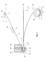
- the device for tapping comprises a hammer 1, with handle 2 and head 3, for instance a small steel ball framed in the end thereof.
- the hammer with handle and head preferably constitute one whole and are manufactured from a well-selected plastic.
- the handle consists of a handle end 4 which is connected through a hinge element 5 with an arm portion 6, having a magnet 7 arranged therein.
- a pin 8 is arranged allowing the hammer to rotate.
- Hinge element 5 and handle end 4 are connected to constitute a hammer rod in one piece.
- arm portion and hammer rod form one whole, with the hammer rod forming a leaf spring portion having a spring constant k between 1.2 and 1.6 N/m.
- the pin 8 fits into a pin hole 22 of a holder 21 of handle driving element 20.
- An electromagnet 23 with core 24 is fixedly connected with this holder 21.
- the leaf spring portion during the "forward" movement can bend so that the ball 3 just taps an egg 10 disposed on a support 11, more particularly between two rollers or hourglass-shaped rollers jointly forming a nest, mounted on a shaft 12, associated with a conveyor of an egg sorting device.
- a microphone 9 With a microphone 9, the acoustic vibrations resulting from tapping can be picked up.
- the eggs disposed on rollers 11 are passed under these hammers 1 to be tapped during transport.
- the further features to be determined can be used for sorting further downstream in the sorting device.
- the S20, S30, and S40 resonance modes can be observed.
- the shape of such a resonance signal for instance of the amplitude, or also of the frequency spectrum, contains information about the condition of the egg shell, i.e. yes/no fracture or crack, egg shell strength, or also information about the contents of the egg.
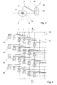
- the hammer is represented in three positions, viz. in rest position 1A, in central position 1B, and in tapping position 1C.
- the hammer rests against a holding element, consisting of a holder block 30 with holder magnet 31, and a stop block 32.
- the operation can be elucidated as follows. From its rest position 1A, after excitation of the electromagnet 23, the hammer 1, through its arm portion 6 having therein magnet 7, is forced to move downwards, to be seen as the "forward" movement.
- position 1B the arm portion 6 butts against a stop 25 which is arranged on the holder 21.
- the device of the invention according to this exemplary embodiment in particular with the handle end 4, makes it possible for this handle end with the ball 3 to bend or swing so far that the ball just taps the egg 10, as indicated in tapping position 1C.
- the pulse which is thus administered is very short in duration, also referred to as Dirac pulse.
- Dirac pulse a very suitable acoustic vibration signal is obtained, to be transformed into a broad frequency spectrum through application of Fourier analysis, in particular using so-called FFT, i.e. Fast Fourier Transform.
- the energization can now be set such that during the return or backward movement, the arm portion is momentarily attracted and the hammer will be retained by the holding element. The ball will then cling to holder magnet 31, while any further bending will be prevented by stop block 32.
- the excitation of the electromagnet 23, and hence the stroke of the reciprocating movement of the hammer 1 can be adjusted and controlled, for instance by first measuring the size, and then using this signal for the purpose of excitation.
- the whole hammer can be manufactured from the same plastic, for instance through injection molding.
- the back-and-forth movement can also take place in a direction other than the vertical direction.
- Fig. 2 schematically represents a situation similar to that in Fig. 1.
- the reciprocating movement of the hammer 1 take place approximately in a vertical plane, with microphone 9 disposed approximately in the "equator" plane, i.e. the plane perpendicular to said vertical plane and likewise passing through the long axis of the article, such as an egg 10 here.
- positions 9' or 9 are also eligible in the same vertical plane through the long axis of the article, depending on the space left clear next to the hammer 1.
- two signal lines are indicated, line 19 for the microphone and line 26 for the electromagnet 23, respectively leading to a signal processing device, not shown, and a control device, not shown either.
- a top plan view of a part of a sorting device 50 is represented, with the positions of the articles, for instance eggs, schematically represented as the intersections 51 of the chain-dotted lines.
- the transport direction of the sorting device is designated by arrow T.
- hammers 1 and handle driving elements 20 are also indicated. In order to tap the eggs several times, the hammers are so arranged that in the example shown, each egg can be tapped four times, without the hammers being in each other's way.
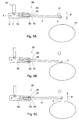
- a second exemplary embodiment according to the invention is shown, in which the arm portion 6 and the handle end 4 are mutually connected through a hinge element 51, for instance a separate pin, or also a joint in which the pin, handle end and arm portion are formed as one whole, for instance through injection molding of a suitable plastic.
- a bistable switch 60 is indicated, consisting in particular of a magnet 61 in the part of the handle end located adjacent the arm portion, as well as two magnets 62 and 63, located at some distance therefrom, in the arm portion 6, with an interspace 64, whilst the handle end clings either to one magnet 62 or to the other magnet 63, which positions constitute snap positions for this handle end.
- the arm portion in the plane referred to will start the forward movement towards the egg 10 represented here, indicated with an arrow F, with the handle end snapped by magnet 63, shown in Fig. 4A.
- the hinge element 51 will allow the handle end to snap from one snap position to the other, the handle end now clinging to magnet 62, whereby the tapping pulse is shortened with great advantage and bouncing is avoided. Ideally, this will take place precisely during the tapping pulse.
- the forward or backward movement is shown in Fig. 4C and indicated with an arrow B, whereby the hammer returns to the starting position and the ball 3 clings to holder magnet 31 again.
- an additional contribution to this movement can be made by suitably exciting the electromagnet in the holder 20.
- the materials can be suitably selected to thereby improve elasticity. Less elastic materials may even suffice, because the bistable switch will prevent bouncing in an advantageous manner.
- a third embodiment is shown.
- the hinge element is a leaf spring 52.
- the operation is otherwise entirely comparable to that of the embodiment according to Fig. 4.
- adhering elements and bistable switches can be used, such as, respectively, springs without adhering elements, or also in combination with electromagnets.
Landscapes
- Life Sciences & Earth Sciences (AREA)
- Chemical & Material Sciences (AREA)
- Physics & Mathematics (AREA)
- Health & Medical Sciences (AREA)
- General Physics & Mathematics (AREA)
- Biochemistry (AREA)
- General Health & Medical Sciences (AREA)
- Analytical Chemistry (AREA)
- Immunology (AREA)
- Pathology (AREA)
- Environmental Sciences (AREA)
- Engineering & Computer Science (AREA)
- Food Science & Technology (AREA)
- Acoustics & Sound (AREA)
- Animal Husbandry (AREA)
- Biodiversity & Conservation Biology (AREA)
- Medicinal Chemistry (AREA)
- Investigating Or Analyzing Materials By The Use Of Ultrasonic Waves (AREA)
Claims (13)
- Vorrichtungen zur Bestimmung des Schwingverhaltens schwingender, gestützter, im allgemeinen runder, im wesentlichen ellipsoider Körper (10), so wie Eier, umfassend:dadurch gekennzeichnet, dassein elastischer Hammer mit einem Griff (4, 5, 6) und einem Kopf (3) zum Anklopfen und dabei solche Körper akustisch in Schwingung bringen,ein Griffantriebselement (20) zum Hin- und Herbewegen des Hammers im wesentlichen in einer Ebene um eine Achse in dem Griff,ein Mikrofon (9) unmittelbar neben und zu dem Körper (10) hin ausgerichtet angeordnet, zur Aufnahme der von dem Körper (10) erzeugten akustischen Schwingungen
undein Signalverarbeitungsmittel zum Verarbeiten der von dem Mikrofon (9) aufgenommenen Signale zum Bestimmen des Schwingverhaltens des Körpers (10),
der Griff neben der Achse aus einem anzutreibenden Armabschnitt (6) besteht, welcher über ein Gelenkelement (5; 51; 52) mit einem Griffende (4) verbunden ist, welches an deren Extremität eine Befestigung aufweist, in der ein Ball (3) als ein Kopf vorhanden ist, während zumindest das Gelenkelement (5; 51; 52) und das Griffende (4) derart verbunden sind, dass sie als einteilige Hammerstange wirken, wobei die Gelenkelement (5; 51; 52)-verbindung zwischen dem Armabschnitt (6) und dem Griffende (4) derart ist, dass nach einer Anregung des Griffantriebselements (20) ein einzelner Anklopf-Impuls erzeugt wird. - Vorrichtung nach Anspruch 1, dadurch gekennzeichnet, dass die Ebene durch die Längsachse des Körpers (10) führt.
- Vorrichtung nach Anspruch 1 oder 2, dadurch gekennzeichnet, dass zumindest ein einzelnes Mikrofon (9) in der Ebene oder durch die Längsachse in einer im wesentlichen rechtwinklig zu der Ebene stehenden zweiten Ebene angeordnet ist.
- Vorrichtungen nach einem der vorhergehenden Ansprüche, dadurch gekennzeichnet, dass die Hammerstange (4, 5) und der Armabschnitt (6) eine Einheit bilden, wobei die Hammerstange (4, 5) eine Blattfeder mit einer Federkonstanten k im Bereich zwischen 1,2 und 1,6 N/m bildet.
- Vorrichtung nach einem der vorhergehenden Ansprüche, dadurch gekennzeichnet, dass das Griffantriebselement (20) weiterhin einen Halter (21) mit einem Stiftloch (22) für einen rechtwinklig zu der ersten Ebene und durch den Armabschnitt (6) verlaufenden Stift (8) aufweisend, mit einem an dem Halter (21) angebrachten Elektromagneten (23) zum Hin- und Herbewegen des Hammers (4, 6) im wesentlichen in der Ebene, mit einem in dem Armabschnitt (6) neben dem Elektromagneten (23) eingefügten Magneten (7; 61) und mit einem Stoppelement (25) für den Armabschnitt (6) während der Vorwärtsbewegung.
- Vorrichtung nach Anspruch 5, dadurch gekennzeichnet, dass das Griffantriebselement (20) weiterhin einen Stopper zum Unterbrechen der Rückwärtsbewegung des Hammers (4, 6) aufweist.
- Vorrichtung nach einem der Ansprüche 5 oder 6, dadurch gekennzeichnet, dass der Ball (3) aus Stahl hergestellt ist und dass das Griffantriebselement (20) weiterhin ein Haltelement (30, 31) aufweist, mit dem der Hammer (4, 6) nach der Rückwärtsbewegung gehalten wird, wobei das Halteelement (30, 31 ) aus einem Stoppblock (32) für den Blattfederabschnitt (4) und aus einem Haltemagnet (31) für den Ball (3) besteht.
- Vorrichtung nach Anspruch 1, dadurch gekennzeichnet, dass die Hammerstange (4, 51; 4, 52) weiterhin mit Mitteln eines bistabilen Schalters mit dem Armabschnitt (6) gekoppelt ist, der Schalter eine erste und zweite Einrastposition aufweist und die Hammerstange (4, 51; 4, 52) entweder zu der ersten Einrastposition oder zu der zweiten Einrastposition bewegbar ist.
- Vorrichtung nach Anspruch 8, dadurch gekennzeichnet, dass die Hammerstange (4, 51; 4, 52) in der Vorwärtsbewegung zu der ersten Einrastposition und in der Rückwärtsbewegung zu der zweiten Einrastposition geschaltet wird.
- Verfahren zur Bestimmung des Schwingverhaltens schwingender Körper (10), wie Eier, dadurch gekennzeichnet, dass ein Anklopfen der Körper (10) mit einer Vorrichtung entsprechend einem der vorgehenden Ansprüche durchgeführt wird.
- Verfahren nach Anspruch 10, dadurch gekennzeichnet, dass das Anklopfen aus einem kurzzeitigen Anklopf-Impuls besteht.
- Verfahren nach Anspruch 10 oder 11, dadurch gekennzeichnet, dass das Verfahren in einer Sortiervorrichtung für Eier angewandt wird.
- Verfahren nach Anspruch 10, 11 oder 12, dadurch gekennzeichnet, dass die Eier zumindest zweimal angeklopft werden.
Priority Applications (1)
| Application Number | Priority Date | Filing Date | Title |
|---|---|---|---|
| EP20020075855 EP1238582B1 (de) | 2001-03-05 | 2002-03-05 | Verfahren und Vorrichtung zur Bestimmung des Schwingverhaltens schwingender Körper wie Eier |
Applications Claiming Priority (3)
| Application Number | Priority Date | Filing Date | Title |
|---|---|---|---|
| EP01200783 | 2001-03-05 | ||
| EP01200783 | 2001-03-05 | ||
| EP20020075855 EP1238582B1 (de) | 2001-03-05 | 2002-03-05 | Verfahren und Vorrichtung zur Bestimmung des Schwingverhaltens schwingender Körper wie Eier |
Publications (3)
| Publication Number | Publication Date |
|---|---|
| EP1238582A2 EP1238582A2 (de) | 2002-09-11 |
| EP1238582A3 EP1238582A3 (de) | 2003-01-29 |
| EP1238582B1 true EP1238582B1 (de) | 2004-06-02 |
Family
ID=26076846
Family Applications (1)
| Application Number | Title | Priority Date | Filing Date |
|---|---|---|---|
| EP20020075855 Expired - Lifetime EP1238582B1 (de) | 2001-03-05 | 2002-03-05 | Verfahren und Vorrichtung zur Bestimmung des Schwingverhaltens schwingender Körper wie Eier |
Country Status (1)
| Country | Link |
|---|---|
| EP (1) | EP1238582B1 (de) |
Families Citing this family (5)
| Publication number | Priority date | Publication date | Assignee | Title |
|---|---|---|---|---|
| EP1198708B1 (de) * | 1999-07-30 | 2004-09-29 | FPS Food Processing Systems B.V. | Verfahren und vorrichtung zur ermittlung der härte eines produkts wie zum beispiel frucht |
| WO2010074572A1 (en) | 2008-12-23 | 2010-07-01 | Fps Food Processing Systems B.V. | Method and apparatus for classifying eggs |
| ES2693100T3 (es) * | 2010-11-05 | 2018-12-07 | Moba Group B.V. | Método y aparato para examinar cáscaras de huevo |
| CN102680573B (zh) * | 2012-05-07 | 2014-07-16 | 刘镇波 | 基于均匀力敲击方法的木材振动性能检测装置 |
| DK2870471T3 (en) | 2012-07-05 | 2018-10-01 | Moba Group Bv | PROCEDURE AND APPARATUS FOR THE DETECTION OF CRACK IN EGGS |
Family Cites Families (5)
| Publication number | Priority date | Publication date | Assignee | Title |
|---|---|---|---|---|
| US3067605A (en) | 1957-08-09 | 1962-12-11 | George N Bliss | Cracked egg detector |
| US3744299A (en) * | 1970-10-28 | 1973-07-10 | Diamond Int Corp | Crack detector |
| NL9401388A (nl) | 1994-08-26 | 1996-04-01 | Leuven K U Res & Dev | Inrichting voor het onderzoeken van eieren. |
| NL1000177C2 (nl) | 1995-04-19 | 1996-10-22 | Food Processing Systems | Probe, inrichting en werkwijze voor het testen van eieren. |
| JP3749961B2 (ja) | 1997-02-14 | 2006-03-01 | 孝子 義▲高▼ | 卵のひび割れ程度検出装置及びこの検出装置を具備した卵選別装置 |
-
2002
- 2002-03-05 EP EP20020075855 patent/EP1238582B1/de not_active Expired - Lifetime
Also Published As
| Publication number | Publication date |
|---|---|
| EP1238582A2 (de) | 2002-09-11 |
| EP1238582A3 (de) | 2003-01-29 |
Similar Documents
| Publication | Publication Date | Title |
|---|---|---|
| US6722201B2 (en) | Method and device for determining vibration characteristics of vibrated articles such as eggs | |
| JP5830105B2 (ja) | 卵を検査するための方法および装置 | |
| US6998559B2 (en) | Detection system for sorting apparatus | |
| EP1198708B1 (de) | Verfahren und vorrichtung zur ermittlung der härte eines produkts wie zum beispiel frucht | |
| EP1238582B1 (de) | Verfahren und Vorrichtung zur Bestimmung des Schwingverhaltens schwingender Körper wie Eier | |
| MXPA03004084A (es) | Metodo y aparato para medir y orientar el mango de un palo de golf. | |
| JP6236404B2 (ja) | 物体の特性を判定するシステム及び方法 | |
| US5696325A (en) | Apparatus for testing eggs | |
| DE69616640T2 (de) | Prüfkopf, Vorrichtung und Verfahren zum Testen von Eiern | |
| JP2606885B2 (ja) | 卵殻の弾性の検査を介して卵殻の亀裂或は損傷の存在を測定する卵の検査方法及びその装置 | |
| US5535538A (en) | Automatic jigging device for fishing | |
| HRP20190587T1 (hr) | Vibrirajući uređaj za branje malog voća | |
| US5129874A (en) | Blank locating apparatus using vibration | |
| US20090199643A1 (en) | Actuation system | |
| JP2006250758A (ja) | 検査方法、検査装置 | |
| US20100199771A1 (en) | Ultrasonic scanning apparatus with a tuning fork-type vibrator | |
| JP2006250757A (ja) | 検査方法、検査装置 | |
| JPH11311585A (ja) | 可変式衝撃試験装置 | |
| US4760731A (en) | Method and apparatus for the stress testing of glass containers arranged hanging | |
| KR101955441B1 (ko) | 시편을 타격하여 특성을 측정하는 시편특성 측정장치 | |
| JP2001074707A (ja) | 農産物内部品質検査用の打撃装置 | |
| SU320831A1 (ru) | Манипулятор устройства для автоматической | |
| JP2003266388A (ja) | 鶏卵殻切断装置 | |
| JP4039259B2 (ja) | 演奏装置 | |
| SU1167492A1 (ru) | Способ определени дефектности издели |
Legal Events
| Date | Code | Title | Description |
|---|---|---|---|
| PUAI | Public reference made under article 153(3) epc to a published international application that has entered the european phase |
Free format text: ORIGINAL CODE: 0009012 |
|
| AK | Designated contracting states |
Kind code of ref document: A2 Designated state(s): AT BE CH CY DE DK ES FI FR GB GR IE IT LI LU MC NL PT SE TR |
|
| AX | Request for extension of the european patent |
Free format text: AL;LT;LV;MK;RO;SI |
|
| PUAL | Search report despatched |
Free format text: ORIGINAL CODE: 0009013 |
|
| AK | Designated contracting states |
Designated state(s): AT BE CH CY DE DK ES FI FR GB GR IE IT LI LU MC NL PT SE TR |
|
| AX | Request for extension of the european patent |
Extension state: AL LT LV MK RO SI |
|
| 17P | Request for examination filed |
Effective date: 20030130 |
|
| 17Q | First examination report despatched |
Effective date: 20030507 |
|
| GRAP | Despatch of communication of intention to grant a patent |
Free format text: ORIGINAL CODE: EPIDOSNIGR1 |
|
| AKX | Designation fees paid |
Designated state(s): DE FR GB IT NL |
|
| GRAS | Grant fee paid |
Free format text: ORIGINAL CODE: EPIDOSNIGR3 |
|
| GRAA | (expected) grant |
Free format text: ORIGINAL CODE: 0009210 |
|
| AK | Designated contracting states |
Kind code of ref document: B1 Designated state(s): DE FR GB IT NL |
|
| REG | Reference to a national code |
Ref country code: GB Ref legal event code: FG4D |
|
| REF | Corresponds to: |
Ref document number: 60200557 Country of ref document: DE Date of ref document: 20040708 Kind code of ref document: P |
|
| REG | Reference to a national code |
Ref country code: IE Ref legal event code: FG4D |
|
| ET | Fr: translation filed | ||
| PGFP | Annual fee paid to national office [announced via postgrant information from national office to epo] |
Ref country code: FR Payment date: 20050322 Year of fee payment: 4 |
|
| PLBE | No opposition filed within time limit |
Free format text: ORIGINAL CODE: 0009261 |
|
| STAA | Information on the status of an ep patent application or granted ep patent |
Free format text: STATUS: NO OPPOSITION FILED WITHIN TIME LIMIT |
|
| PGFP | Annual fee paid to national office [announced via postgrant information from national office to epo] |
Ref country code: DE Payment date: 20050511 Year of fee payment: 4 |
|
| 26N | No opposition filed |
Effective date: 20050303 |
|
| PGFP | Annual fee paid to national office [announced via postgrant information from national office to epo] |
Ref country code: GB Payment date: 20060308 Year of fee payment: 5 |
|
| PGFP | Annual fee paid to national office [announced via postgrant information from national office to epo] |
Ref country code: IT Payment date: 20060331 Year of fee payment: 5 |
|
| PG25 | Lapsed in a contracting state [announced via postgrant information from national office to epo] |
Ref country code: NL Free format text: LAPSE BECAUSE OF NON-PAYMENT OF DUE FEES Effective date: 20061001 |
|
| PG25 | Lapsed in a contracting state [announced via postgrant information from national office to epo] |
Ref country code: DE Free format text: LAPSE BECAUSE OF NON-PAYMENT OF DUE FEES Effective date: 20061003 |
|
| NLV4 | Nl: lapsed or anulled due to non-payment of the annual fee |
Effective date: 20061001 |
|
| REG | Reference to a national code |
Ref country code: FR Ref legal event code: ST Effective date: 20061130 |
|
| GBPC | Gb: european patent ceased through non-payment of renewal fee |
Effective date: 20070305 |
|
| PG25 | Lapsed in a contracting state [announced via postgrant information from national office to epo] |
Ref country code: FR Free format text: LAPSE BECAUSE OF NON-PAYMENT OF DUE FEES Effective date: 20060331 |
|
| PG25 | Lapsed in a contracting state [announced via postgrant information from national office to epo] |
Ref country code: GB Free format text: LAPSE BECAUSE OF NON-PAYMENT OF DUE FEES Effective date: 20070305 |
|
| PG25 | Lapsed in a contracting state [announced via postgrant information from national office to epo] |
Ref country code: IT Free format text: LAPSE BECAUSE OF NON-PAYMENT OF DUE FEES Effective date: 20070305 |