EP1238301B1 - Fiber retaining system - Google Patents
Fiber retaining system Download PDFInfo
- Publication number
- EP1238301B1 EP1238301B1 EP00991967A EP00991967A EP1238301B1 EP 1238301 B1 EP1238301 B1 EP 1238301B1 EP 00991967 A EP00991967 A EP 00991967A EP 00991967 A EP00991967 A EP 00991967A EP 1238301 B1 EP1238301 B1 EP 1238301B1
- Authority
- EP
- European Patent Office
- Prior art keywords
- fiber
- restraining device
- optical fiber
- splice
- housing
- Prior art date
- Legal status (The legal status is an assumption and is not a legal conclusion. Google has not performed a legal analysis and makes no representation as to the accuracy of the status listed.)
- Expired - Lifetime
Links
- 239000000835 fiber Substances 0.000 title claims abstract description 87
- 239000013307 optical fiber Substances 0.000 claims abstract description 61
- 230000000452 restraining effect Effects 0.000 claims description 34
- 238000005728 strengthening Methods 0.000 claims description 12
- 230000003014 reinforcing effect Effects 0.000 claims description 10
- 238000000034 method Methods 0.000 claims description 8
- 230000008878 coupling Effects 0.000 claims 1
- 238000010168 coupling process Methods 0.000 claims 1
- 238000005859 coupling reaction Methods 0.000 claims 1
- 229910000831 Steel Inorganic materials 0.000 abstract description 7
- 239000010959 steel Substances 0.000 abstract description 7
- 230000000712 assembly Effects 0.000 abstract description 5
- 238000000429 assembly Methods 0.000 abstract description 5
- 229910000797 Ultra-high-strength steel Inorganic materials 0.000 abstract 1
- 239000011248 coating agent Substances 0.000 description 3
- 238000000576 coating method Methods 0.000 description 3
- 230000004927 fusion Effects 0.000 description 3
- RYGMFSIKBFXOCR-UHFFFAOYSA-N Copper Chemical compound [Cu] RYGMFSIKBFXOCR-UHFFFAOYSA-N 0.000 description 2
- 230000006835 compression Effects 0.000 description 2
- 238000007906 compression Methods 0.000 description 2
- 229910052802 copper Inorganic materials 0.000 description 2
- 239000010949 copper Substances 0.000 description 2
- 238000004382 potting Methods 0.000 description 2
- 230000001681 protective effect Effects 0.000 description 2
- 239000000853 adhesive Substances 0.000 description 1
- 230000001070 adhesive effect Effects 0.000 description 1
- 230000015572 biosynthetic process Effects 0.000 description 1
- 238000013461 design Methods 0.000 description 1
- 239000011521 glass Substances 0.000 description 1
- 239000003292 glue Substances 0.000 description 1
- 230000014759 maintenance of location Effects 0.000 description 1
- 239000000463 material Substances 0.000 description 1
- 239000002184 metal Substances 0.000 description 1
- 229910052751 metal Inorganic materials 0.000 description 1
- 238000012986 modification Methods 0.000 description 1
- 230000004048 modification Effects 0.000 description 1
- 239000006223 plastic coating Substances 0.000 description 1
- 239000010453 quartz Substances 0.000 description 1
- 238000012552 review Methods 0.000 description 1
- VYPSYNLAJGMNEJ-UHFFFAOYSA-N silicon dioxide Inorganic materials O=[Si]=O VYPSYNLAJGMNEJ-UHFFFAOYSA-N 0.000 description 1
- XLYOFNOQVPJJNP-UHFFFAOYSA-N water Substances O XLYOFNOQVPJJNP-UHFFFAOYSA-N 0.000 description 1
- 238000004078 waterproofing Methods 0.000 description 1
Images


Classifications
-
- G—PHYSICS
- G02—OPTICS
- G02B—OPTICAL ELEMENTS, SYSTEMS OR APPARATUS
- G02B6/00—Light guides; Structural details of arrangements comprising light guides and other optical elements, e.g. couplings
- G02B6/44—Mechanical structures for providing tensile strength and external protection for fibres, e.g. optical transmission cables
- G02B6/4439—Auxiliary devices
- G02B6/4471—Terminating devices ; Cable clamps
- G02B6/4476—Terminating devices ; Cable clamps with heat-shrinkable elements
-
- G—PHYSICS
- G02—OPTICS
- G02B—OPTICAL ELEMENTS, SYSTEMS OR APPARATUS
- G02B6/00—Light guides; Structural details of arrangements comprising light guides and other optical elements, e.g. couplings
- G02B6/44—Mechanical structures for providing tensile strength and external protection for fibres, e.g. optical transmission cables
- G02B6/4439—Auxiliary devices
- G02B6/444—Systems or boxes with surplus lengths
- G02B6/44528—Patch-cords; Connector arrangements in the system or in the box
-
- G—PHYSICS
- G02—OPTICS
- G02B—OPTICAL ELEMENTS, SYSTEMS OR APPARATUS
- G02B6/00—Light guides; Structural details of arrangements comprising light guides and other optical elements, e.g. couplings
- G02B6/44—Mechanical structures for providing tensile strength and external protection for fibres, e.g. optical transmission cables
- G02B6/4439—Auxiliary devices
- G02B6/4471—Terminating devices ; Cable clamps
Definitions
- the present invention relates to the retention and protection of loose spliced optical fibers. More specifically, the invention relates to a housing for containing and protecting a fiber optic splice and a portion of the optical fibers on opposite sides leading to the splice.
- the cable 2 includes an outer insulating plastic coating 4, a copper sheath 6 inside the outer coating 4, and high strength members, such as steel wires 8, inside the copper sheath 6.
- a loose tube 10 is contained within the steel wires 8, and one or more isolated optical fibers 12 are contained within the loose tube 10. This permits the fibers 12 to move with respect to the steel wires 8, the sheath 6 and the coating 4.
- This cable arrangement has been found to be desirable in many high strength applications.
- splicing As neither the cables nor the fibers can be made and deployed in infinite lengths, sections of the cables and the fibers are attached together.
- the fibers are typically attached to each other by a process known as splicing.
- these spliced sections are commonly contained in a watertight housing, which is frequently referred to as a joint box.
- Such housings or joint boxes are also used when it is necessary to make splices in the field.
- tension is applied to the cable, such as during the deployment of the cable underwater by a ship, it is undesirable to have the splice absorb the applied tension forces or to have the spliced portion leave the joint box and go back inside the cable.
- EP 0389206 discloses a cable joint in which a first clamp arrangement is used to clamp the optic fibre within its housing and a second clamp arrangement comprising tapered clamps is used to clamp the tensile strength members.
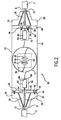
- FIG. 2 schematically depicts the housing or joint box 20 connecting the free ends of two cables 2 together.
- the cables 2 are preferably of the type shown in Figure 1 such that the optical fibers 12 can move longitudinally with respect to the remainder of the cable 2.
- the optical fibers 12 of the cables 2 are joined by a splice at splice location 90.
- the fibers 12 are restrained between the ends of the joint box 20 and the splice location 90.
- the fibers 12 are restrained on both sides of the splice location 90 at a location longitudinally spaced from the splice location 90. This eliminates the need to provide a significant amount of slack for the optical fibers 12.
- the joint box 20 includes cable termination sections 24 at its longitudinal ends, and a center section 22 disposed between, and connecting, the cable termination sections 24.
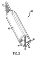
- Each cable termination section 24 includes a body 26 with a cone-shaped hollow cavity therein, and a cone-shaped plug and sleeve configuration 28 that fits within the hollow cavity.
- These elements function substantially as disclosed in U.S. Pat. No. 4,507,008 .
- the high strength steel wires 8 of the cables 2 are clamped between the hollow cavity of the body 26 and the plug and sleeve 28, and the outer surface of the sleeve is malleable which deforms around the high strength steel wire 8 as the plug is inserted.
- the body 26 and the plug and sleeve configuration 28 are hollow along their central axis 30. This enables the fibers 12 to extend unrestrained therethrough.
- the shelf or center section 22 is disposed between the cable termination sections 24 and houses and protects the spliced section of the fibers 12.
- the center section 22 includes a pair of opposing ferrule retaining assemblies 34 and a central body 32 disposed between, and connected to, the ferrule retaining assemblies 34.
- the fibers 12 are spliced together at splice location 90.
- the splice 90 is typically protected by a splice reinforcing device 92 which may be mass fusion splint or another structure known for strengthening the splice region.
- the "spliced region" for spliced fibers is herein defined as the splice itself and a small distance on either longitudinal side of the splice that is used for strengthening the splice.
- the central body 32 further includes a shelf surface 36 upon which the splice reinforcing device 92 may rest.
- the shelf surface 36 may be any desirable size and shape, and may span the entire body 32 if desired.
- one or more restraints 38 which may take any form, are preferably used to fix the splice reinforcing device 92 to the shelf surface 36. This prevents excess movement of the spliced region of the optical fibers 12.
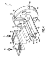
- Each ferrule retaining assembly 34 includes a shelf retainer 40 and a ferrule retainer 42.
- the shelf retainer 40 is attached on one side to a cable termination section 24 and to central body 32 on its other side.
- the shelf retainer 40 is generally disc-shaped and its diameter is slightly smaller than the sizes of the interfacing side of the cable termination section 24 and the longitudinal ends of central body 32.
- Each ferrule retaining assembly 34 is attached to its respective cable termination section 24 by any suitable arrangement such as by hardware.
- shelf retainer 40 of the ferrule retaining assembly 34 may be provided with countersunk holes 44 and the body 26 of the cable termination section 24 may be provided with a threaded hole 46.
- a screw 48 may be used to extend through each countersunk hole 44 in the shelf retainer 40 and threadably engage with an aligned threaded hole 46 in the body 26 of the cable termination section 24.
- alternative attachment arrangements can be used.
- Figure 2 schematically illustrates these attachment elements only on the left side of the joint box 20. However, similar hardware is preferably used on the right side.
- the shelf retainer 40 On its circumference, the shelf retainer 40 includes outwardly projecting alignment pins 50 and preferably at least two recessed holes 52. These features permit the locking of the shelf retainer 40 to the central body 32.
- the pins 50 enter slots, not shown, on the central body 32, and the two are rotated with respect to each other until alignment with locking members on the inside of the central body 32 is reached through the recessed holes 52 in the shelf retainer 40.
- These parts are then locked together with a screw or another device such as a spring biased locking pin.
- This locking arrangement has been used in other joint boxes and other devices and may be referred to as a "bayonette-type" locking arrangement. However, one of ordinary skill in the art will recognize that alternative attachment arrangements can be used in lieu of the "bayonette-type" locking arrangement.
- the shelf retainer 40 further includes a slot 54 and a pair of laterally-spaced countersunk holes 56.
- the slot 54 permits the passage of the optical fibers 12 therethrough.
- the countersunk holes 56 are located on the side opposite from the other countersunk holes 44, and are used for attaching the shelf retainer 40 to the ferrule retainer 42.
- the ferrule retainer 42 includes corresponding threaded holes 58 therein.
- Conventional hardware e.g., screws 60 and washers, may be used to extend through the aligned holes 56 and 58 and fix the shelf retainer 40 to the ferrule retainer 42.
- Figure 2 schematically illustrates these attachment elements only on the right side of the joint box 20. However, similar hardware is preferably used on the left side. Alternative attachment arrangements could be used.
- the shelf retainer 40 and the ferrule retainer 42 could be integral with each other, e.g., machined from a single piece.
- the ferrule retainer 42 When attached to the shelf retainer 40, the ferrule retainer 42 is substantially horizontal and extends in a longitudinal direction.
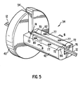
- the ferrule retainer 42 includes a longitudinal trough 62, which preferably has a curved bottom surface 64, an inner side 66 closest to the splice, and a top cover 68.
- the trough 62 retains a ferrule 80, as described in more detail later herein, with the curved bottom surface 64 generally approximating the lower contour of the ferrule 80.
- the trough 62 further includes an outer slot 74 at the end of the trough 62 distal from the splice location 90 and an inner slot 76 through the inner side 66 of the trough 62 on the side proximal to the splice location 90.
- Both slots 74 and 76 are sized to permit the optical fibers 12 to pass therethrough, but are narrower than the outer diameter of the ferrule 80 to prevent the passage of the ferrule 80 therethrough.
- the reduced sized slots 74 and 76 at the outer and inner ends of the trough 62 are formed by shoulders 70 and 72. The shoulders 70 and 72 may be machined into the main body of the ferrule retainer.
- an inner side cover with a slot could be attached to the inner side of the trough 62 through any desired arrangement, such as hardware.
- the inner shoulders 72 could then be created by the difference in sizes between the trough 62 and a slot in the inner side cover.
- the top cover 68 preferably attaches to the main body of the ferrule retainer 42 by the use of threaded holes 77 in the top surface of the main body of the ferrule retainer. Holes 78 in the top cover 68 correspondingly align with the holes 77. Screws 79, some of which are shown in Figure 4 , may be used to fixedly attach the top cover 68 to the main body of the ferrule retainer, via the aligned holes 77 and 78. Alternative attachment arrangements could be used.
- the enlarged fiber supporting elements or ferrules 80 are formed by aligning the optical fibers 12 and splinting them. Such a process has been done in the prior art to reinforce spliced fibers and such an arrangement may also be used in the present invention for the splice reinforcing device 92.
- the splint 82 consists of a pair of semicylindrical supports 84 and 86 on opposing sides of the aligned optical fibers 12.
- one support 84 is made from glass or quartz, while the other support 86 is made from a plastic material.
- a shrink tube 88 is preferably used to fix the semicylindrical supports 84 and 86 with respect to the aligned fibers 12 and provide a gripping force on the fibers therebetween. Adhesive is applied around the aligned fibers and between the semicylindrical supports 84 and 86.
- the loose optical fibers 12 are ribbonized. That is, they are organized and attached to each other in a line. This facilitates the formation of the ferrule 80.
- the entire lengths of optical fibers 12 may be ribbonized between each ferrule 80 and the splice reinforcing device 92.
- the end of two cable sections are attached to the cable termination sections 24 as described above.
- the fibers 12 Prior to or after that step, at least a portion of the fibers 12 are aligned and ribbonized.
- the ribbonized portion should at least approximately cover the area where the ferrule 80 will be formed.
- a ferrule 80 including a splint 82 is formed over that area as described above.
- the ferrule retainer assembly 34 is fully assembled except for the attachment of the top cover 68.
- the fibers 12 are oriented vertically and are placed within slot 54 of the shelf retainer 40.
- the shelf retainer 40 of the ferrule retainer assembly 34 is attached to the cable termination section 24.
- the ferrule 80 is placed inside the trough 62 longitudinally between the shoulders 72 and 74.
- the fibers 12 are preferably ribbonized in this area and extend through the inner and outer slots 74 and 76 in alignment.
- the top cover 68 is attached to the remainder of the ferrule retainer assembly 34.
- the bottom of the top cover 68 includes a compressible gasket 69 to assist in applying a desired amount of compression to the ferrule 80.
- the cable termination sections 24 with the attached ferrule retainer assemblies 34 are attached to the central body 32.
- the free ends of the optical fibers 12 are then spliced, either individually or as a mass fusion splice, and are reinforced, and attached to the shelf surface 36 in any desirable manner.
- Sufficient slack in the optical fibers 12 between the ferrule 80 and the splice reinforcing device 92 is provided to carry out the splicing operation. If desired, slack from the fibers 12 may be coiled onto the central body. Finally, a metal cover, not shown, is attached around the body 32, and a plastic sleeve, also not shown, may sealingly surround the entire joint box 20 in a conventional manner for waterproofing and insulating purposes.
- the fibers 12 are aligned and ribbonized.
- the ribbonized fibers 12 are then “potted” by being embedded in a larger protective structure or body, the ferrule 80. This "potting” restrains the fibers 12 at a location adjacent the cable termination sections 24 and spaced from the point of fusion or splice and any reinforcing device used at the splice to isolate any forces applied to the fiber from the splice.
- the ferrule 80 is sufficiently flexible in shear not to harm the coating on the fibers. Further, it is sufficiently rigid in compression to prevent the fibers from translating into or out of the ferrule 80, as the ferrule 80 is restrained in the trough 62.
- the amount of force applied to restrain the outer surface of the ferrule will be a function of the pressure applied from the top cover 68 and the force applied by the outer retaining shoulder 70 on the side that the tension force is applied.
- the fibers 12 are sufficiently gripped by the splint 82, and therefore, the fibers 12 are prevented from moving into the cable 2 and the force on the fibers 12 is transferred to joint box 20 via the ferrule retainer assembly 34 via the shoulders and the friction between the outside of the ferrule 80 and the trough 62 and top cover 68. Additionally, the region of the splice is isolated from these forces as they are transferred from the ferrule 80 directly to the joint box 20. As the effective transference of the tensile forces is a function of the length of contact between the fibers and the splint, the length of the splint can be designed based on expected parameters.
- the invention depicts and describes a plurality of optical fibers 12 in the cable 2, the invention works similarly and is applicable for use with a cable having a single optical fiber. Further, depending on the length of the ferrule and amount of expected forces, it is also possible to create a ferrule and pot the fibers without the use of a splint, relying primarily on a protective encasement made from a glue. Additionally, in lieu of the potting or splint method described above, other methods of restraining the fibers prior to the splice may be used.
Landscapes
- Physics & Mathematics (AREA)
- General Physics & Mathematics (AREA)
- Optics & Photonics (AREA)
- Light Guides In General And Applications Therefor (AREA)
- Cable Accessories (AREA)
- Paper (AREA)
- Mechanical Coupling Of Light Guides (AREA)
- Prostheses (AREA)
- Medicines That Contain Protein Lipid Enzymes And Other Medicines (AREA)
- Medicines Containing Material From Animals Or Micro-Organisms (AREA)
- Load-Engaging Elements For Cranes (AREA)
Applications Claiming Priority (3)
| Application Number | Priority Date | Filing Date | Title |
|---|---|---|---|
| US399752 | 1999-09-21 | ||
| US09/399,752 US6438300B1 (en) | 1999-09-21 | 1999-09-21 | Fiber retaining system |
| PCT/US2000/025915 WO2001022144A2 (en) | 1999-09-21 | 2000-09-21 | Fiber retaining system |
Publications (2)
| Publication Number | Publication Date |
|---|---|
| EP1238301A2 EP1238301A2 (en) | 2002-09-11 |
| EP1238301B1 true EP1238301B1 (en) | 2010-08-11 |
Family
ID=23580816
Family Applications (1)
| Application Number | Title | Priority Date | Filing Date |
|---|---|---|---|
| EP00991967A Expired - Lifetime EP1238301B1 (en) | 1999-09-21 | 2000-09-21 | Fiber retaining system |
Country Status (9)
| Country | Link |
|---|---|
| US (1) | US6438300B1 (cg-RX-API-DMAC7.html) |
| EP (1) | EP1238301B1 (cg-RX-API-DMAC7.html) |
| JP (1) | JP4112226B2 (cg-RX-API-DMAC7.html) |
| AT (1) | ATE477512T1 (cg-RX-API-DMAC7.html) |
| AU (1) | AU2903301A (cg-RX-API-DMAC7.html) |
| CA (1) | CA2388460C (cg-RX-API-DMAC7.html) |
| DE (1) | DE60044820D1 (cg-RX-API-DMAC7.html) |
| DK (1) | DK1238301T3 (cg-RX-API-DMAC7.html) |
| WO (1) | WO2001022144A2 (cg-RX-API-DMAC7.html) |
Families Citing this family (10)
| Publication number | Priority date | Publication date | Assignee | Title |
|---|---|---|---|---|
| JPH0713156A (ja) * | 1993-06-22 | 1995-01-17 | Ohtsu Tire & Rubber Co Ltd :The | 導光板装置 |
| JP2004219953A (ja) * | 2003-01-17 | 2004-08-05 | Kddi Submarine Cable Systems Inc | 光ファイバ引留め方法及び装置 |
| US8328431B2 (en) * | 2010-02-01 | 2012-12-11 | Tyco Electronics Subsea Communications Llc | Coupling multiple conductor undersea optical cables to an undersea device with an isolated bypass conductive path across the undersea device |
| US8457461B2 (en) * | 2010-04-16 | 2013-06-04 | Adc Telecommunications, Inc. | Fiber optic cable assembly and method of making the same |
| DE102010027224A1 (de) | 2010-07-15 | 2012-01-19 | Forschungszentrum Jülich GmbH | Elektrode zur Erzeugung eines Plasmas, Plasmakammer mit dieser Elektrode und Verfahren zur in situ-Analyse oder -in situ-Bearbeitung einer Schicht oder des Plasmas |
| US9500830B2 (en) | 2012-09-28 | 2016-11-22 | Commscope Technologies Llc | Splice-on cable breakout assembly |
| US9658417B2 (en) * | 2013-12-02 | 2017-05-23 | Tyco Electronics Subsea Communications Llc | Conductive water blocking material including metallic particles and an optical cable and method of constructing an optical cable including the same |
| JP6628247B2 (ja) * | 2016-05-19 | 2020-01-08 | Seiオプティフロンティア株式会社 | 光ファイバ融着接続部の補強装置およびそれを備えた融着接続機 |
| US10288802B2 (en) * | 2017-05-02 | 2019-05-14 | Teraxion | Optical fiber heat dissipation package |
| US11009672B2 (en) * | 2018-02-28 | 2021-05-18 | Commscope Technologies Llc | Device and method for aerially suspending an optical cable termination box |
Citations (1)
| Publication number | Priority date | Publication date | Assignee | Title |
|---|---|---|---|---|
| EP0389206A2 (en) * | 1989-03-21 | 1990-09-26 | STC Submarine Systems Limited | Jointing optical fibre cables |
Family Cites Families (12)
| Publication number | Priority date | Publication date | Assignee | Title |
|---|---|---|---|---|
| FR2507331A1 (fr) | 1981-06-05 | 1982-12-10 | Cables De Lyon Geoffroy Delore | Dispositif de jonction des extremites de deux cables sous-marins a fibres optiques |
| US4507008A (en) | 1983-05-13 | 1985-03-26 | At&T Bell Laboratories | Stranded cable termination arrangement |
| GB2224757B (en) | 1988-11-10 | 1992-08-12 | Stc Plc | Cable anchorage |
| NO171934C (no) | 1991-01-03 | 1993-05-19 | Alcatel Stk As | Fiberoptisk skjoetehus |
| FR2693805B1 (fr) | 1992-07-16 | 1994-09-02 | Alcatel Cable | Boîte de jonction de câbles optiques sous-marins. |
| FR2729230B1 (fr) | 1995-01-09 | 1997-03-28 | Crespel Daniel | Dispositif de fixation, de reprise de masse et d'etancheite pour cable optique |
| FR2733843B1 (fr) | 1995-05-03 | 1997-05-30 | Alcatel Submarcom | Dispositif organiseur de connexion de cables a fibres optiques et boite de jonction de cables optiques |
| FR2734651B1 (fr) * | 1995-05-24 | 1997-06-20 | Alcatel Cable Interface | Boitier de raccordement de fibre optique |
| US5642451A (en) * | 1995-12-28 | 1997-06-24 | The United States Of America As Represented By The Secretary Of The Navy | Fiberoptic cable junction |
| GB2312968B (en) * | 1996-05-09 | 2000-09-13 | Daewoo Telecom Ltd | Splicer for light waveguides |
| CA2267891A1 (en) | 1996-10-10 | 1998-04-16 | Tyco Submarine Systems Ltd. | Submarine optical cable joint with terminating sockets |
| FR2782172B1 (fr) * | 1998-08-04 | 2001-11-30 | Pouyet Sa | Dispositif d'entree de cable a fibres optiques |
-
1999
- 1999-09-21 US US09/399,752 patent/US6438300B1/en not_active Expired - Lifetime
-
2000
- 2000-09-21 DE DE60044820T patent/DE60044820D1/de not_active Expired - Lifetime
- 2000-09-21 WO PCT/US2000/025915 patent/WO2001022144A2/en not_active Ceased
- 2000-09-21 AU AU29033/01A patent/AU2903301A/en not_active Abandoned
- 2000-09-21 JP JP2001525456A patent/JP4112226B2/ja not_active Expired - Lifetime
- 2000-09-21 EP EP00991967A patent/EP1238301B1/en not_active Expired - Lifetime
- 2000-09-21 AT AT00991967T patent/ATE477512T1/de not_active IP Right Cessation
- 2000-09-21 DK DK00991967.1T patent/DK1238301T3/da active
- 2000-09-21 CA CA2388460A patent/CA2388460C/en not_active Expired - Lifetime
Patent Citations (1)
| Publication number | Priority date | Publication date | Assignee | Title |
|---|---|---|---|---|
| EP0389206A2 (en) * | 1989-03-21 | 1990-09-26 | STC Submarine Systems Limited | Jointing optical fibre cables |
Also Published As
| Publication number | Publication date |
|---|---|
| DE60044820D1 (de) | 2010-09-23 |
| US6438300B1 (en) | 2002-08-20 |
| ATE477512T1 (de) | 2010-08-15 |
| WO2001022144B1 (en) | 2001-10-11 |
| EP1238301A2 (en) | 2002-09-11 |
| CA2388460A1 (en) | 2001-03-29 |
| DK1238301T3 (da) | 2010-09-20 |
| WO2001022144A2 (en) | 2001-03-29 |
| WO2001022144A9 (en) | 2002-11-21 |
| CA2388460C (en) | 2010-09-14 |
| AU2903301A (en) | 2001-04-24 |
| WO2001022144A3 (en) | 2001-08-16 |
| JP2003510994A (ja) | 2003-03-18 |
| JP4112226B2 (ja) | 2008-07-02 |
Similar Documents
| Publication | Publication Date | Title |
|---|---|---|
| US6728451B2 (en) | Optical fiber holding structure and method of making same | |
| ES2710111T3 (es) | Recubrimiento de tracción mejorado para jalar un cable de fibra óptica a lo largo de un conducto | |
| US5241611A (en) | Cable joint | |
| US4626067A (en) | Method of breaking out and terminating fiber optic elements from a multifiber cable | |
| JP2868828B2 (ja) | 光ファイバケーブル接合装置 | |
| US20020164130A1 (en) | Fiber optic module attachment including a fiber locating connector | |
| CN109477943B (zh) | 带有加固的自支撑系绳的光学终端封装件 | |
| BRPI0621975A2 (pt) | Adaptador de cabo para um cabo de fibras ópticas, sistema para plugar um cabo de fibra óptica em um receptáculo de fibra óptica, e, método para instalar um cabo de fibras ópticas em um receptáculo de fibras ópticas | |
| EP1238301B1 (en) | Fiber retaining system | |
| CN102576135A (zh) | 接头装置及制造分叉纤维光缆的方法 | |
| EP2255235B1 (en) | Method of attachment of a connector to a fiber optic cable | |
| SK280421B6 (sk) | Ťažná hlavica na optický kábel | |
| KR101471018B1 (ko) | 중간 브랜칭을 위한 광 케이블의 안내 및 접속 작업에 적합한 광 케이블 접속 케이싱 | |
| EP1175634B1 (en) | Bulbous configured fiber optic splice closure and associated methods | |
| US6377735B1 (en) | Fiber retaining system | |
| JP4800085B2 (ja) | 光クロージャ | |
| WO1995006891A1 (en) | Optical fibre termination | |
| JP2661960B2 (ja) | 多心光コード分岐部 | |
| JP2020038285A (ja) | 光ファイバ引留め装置 | |
| JPS5852608A (ja) | 光フアイバの接続箱 |
Legal Events
| Date | Code | Title | Description |
|---|---|---|---|
| PUAI | Public reference made under article 153(3) epc to a published international application that has entered the european phase |
Free format text: ORIGINAL CODE: 0009012 |
|
| 17P | Request for examination filed |
Effective date: 20020422 |
|
| AK | Designated contracting states |
Kind code of ref document: A2 Designated state(s): AT BE CH CY DE DK ES FI FR GB GR IE IT LI LU MC NL PT SE |
|
| 17Q | First examination report despatched |
Effective date: 20060803 |
|
| GRAP | Despatch of communication of intention to grant a patent |
Free format text: ORIGINAL CODE: EPIDOSNIGR1 |
|
| RAP1 | Party data changed (applicant data changed or rights of an application transferred) |
Owner name: TYCO ELECTRONICS SUBSEA COMMUNICATIONS LLC |
|
| GRAS | Grant fee paid |
Free format text: ORIGINAL CODE: EPIDOSNIGR3 |
|
| GRAA | (expected) grant |
Free format text: ORIGINAL CODE: 0009210 |
|
| AK | Designated contracting states |
Kind code of ref document: B1 Designated state(s): AT BE CH CY DE DK ES FI FR GB GR IE IT LI LU MC NL PT SE |
|
| REG | Reference to a national code |
Ref country code: GB Ref legal event code: FG4D |
|
| REG | Reference to a national code |
Ref country code: CH Ref legal event code: EP |
|
| REG | Reference to a national code |
Ref country code: IE Ref legal event code: FG4D |
|
| REG | Reference to a national code |
Ref country code: DK Ref legal event code: T3 |
|
| REF | Corresponds to: |
Ref document number: 60044820 Country of ref document: DE Date of ref document: 20100923 Kind code of ref document: P |
|
| REG | Reference to a national code |
Ref country code: GR Ref legal event code: EP Ref document number: 20100402104 Country of ref document: GR |
|
| REG | Reference to a national code |
Ref country code: NL Ref legal event code: VDEP Effective date: 20100811 |
|
| PG25 | Lapsed in a contracting state [announced via postgrant information from national office to epo] |
Ref country code: AT Free format text: LAPSE BECAUSE OF FAILURE TO SUBMIT A TRANSLATION OF THE DESCRIPTION OR TO PAY THE FEE WITHIN THE PRESCRIBED TIME-LIMIT Effective date: 20100811 Ref country code: FI Free format text: LAPSE BECAUSE OF FAILURE TO SUBMIT A TRANSLATION OF THE DESCRIPTION OR TO PAY THE FEE WITHIN THE PRESCRIBED TIME-LIMIT Effective date: 20100811 Ref country code: NL Free format text: LAPSE BECAUSE OF FAILURE TO SUBMIT A TRANSLATION OF THE DESCRIPTION OR TO PAY THE FEE WITHIN THE PRESCRIBED TIME-LIMIT Effective date: 20100811 |
|
| PG25 | Lapsed in a contracting state [announced via postgrant information from national office to epo] |
Ref country code: CY Free format text: LAPSE BECAUSE OF FAILURE TO SUBMIT A TRANSLATION OF THE DESCRIPTION OR TO PAY THE FEE WITHIN THE PRESCRIBED TIME-LIMIT Effective date: 20100811 Ref country code: PT Free format text: LAPSE BECAUSE OF FAILURE TO SUBMIT A TRANSLATION OF THE DESCRIPTION OR TO PAY THE FEE WITHIN THE PRESCRIBED TIME-LIMIT Effective date: 20101213 |
|
| PG25 | Lapsed in a contracting state [announced via postgrant information from national office to epo] |
Ref country code: BE Free format text: LAPSE BECAUSE OF FAILURE TO SUBMIT A TRANSLATION OF THE DESCRIPTION OR TO PAY THE FEE WITHIN THE PRESCRIBED TIME-LIMIT Effective date: 20100811 Ref country code: SE Free format text: LAPSE BECAUSE OF FAILURE TO SUBMIT A TRANSLATION OF THE DESCRIPTION OR TO PAY THE FEE WITHIN THE PRESCRIBED TIME-LIMIT Effective date: 20100811 |
|
| PG25 | Lapsed in a contracting state [announced via postgrant information from national office to epo] |
Ref country code: MC Free format text: LAPSE BECAUSE OF NON-PAYMENT OF DUE FEES Effective date: 20100930 |
|
| REG | Reference to a national code |
Ref country code: CH Ref legal event code: PL |
|
| PLBE | No opposition filed within time limit |
Free format text: ORIGINAL CODE: 0009261 |
|
| STAA | Information on the status of an ep patent application or granted ep patent |
Free format text: STATUS: NO OPPOSITION FILED WITHIN TIME LIMIT |
|
| PG25 | Lapsed in a contracting state [announced via postgrant information from national office to epo] |
Ref country code: ES Free format text: LAPSE BECAUSE OF FAILURE TO SUBMIT A TRANSLATION OF THE DESCRIPTION OR TO PAY THE FEE WITHIN THE PRESCRIBED TIME-LIMIT Effective date: 20101122 |
|
| 26N | No opposition filed |
Effective date: 20110512 |
|
| PG25 | Lapsed in a contracting state [announced via postgrant information from national office to epo] |
Ref country code: LI Free format text: LAPSE BECAUSE OF NON-PAYMENT OF DUE FEES Effective date: 20100930 Ref country code: CH Free format text: LAPSE BECAUSE OF NON-PAYMENT OF DUE FEES Effective date: 20100930 Ref country code: IE Free format text: LAPSE BECAUSE OF NON-PAYMENT OF DUE FEES Effective date: 20100921 |
|
| REG | Reference to a national code |
Ref country code: DE Ref legal event code: R097 Ref document number: 60044820 Country of ref document: DE Effective date: 20110512 |
|
| PGFP | Annual fee paid to national office [announced via postgrant information from national office to epo] |
Ref country code: DK Payment date: 20110927 Year of fee payment: 12 |
|
| PG25 | Lapsed in a contracting state [announced via postgrant information from national office to epo] |
Ref country code: LU Free format text: LAPSE BECAUSE OF NON-PAYMENT OF DUE FEES Effective date: 20100921 |
|
| PGFP | Annual fee paid to national office [announced via postgrant information from national office to epo] |
Ref country code: GR Payment date: 20120927 Year of fee payment: 13 |
|
| PGFP | Annual fee paid to national office [announced via postgrant information from national office to epo] |
Ref country code: IT Payment date: 20120924 Year of fee payment: 13 |
|
| REG | Reference to a national code |
Ref country code: DK Ref legal event code: EBP Effective date: 20130930 |
|
| REG | Reference to a national code |
Ref country code: GR Ref legal event code: ML Ref document number: 20100402104 Country of ref document: GR Effective date: 20140403 |
|
| PG25 | Lapsed in a contracting state [announced via postgrant information from national office to epo] |
Ref country code: IT Free format text: LAPSE BECAUSE OF NON-PAYMENT OF DUE FEES Effective date: 20130921 Ref country code: GR Free format text: LAPSE BECAUSE OF NON-PAYMENT OF DUE FEES Effective date: 20140403 |
|
| PG25 | Lapsed in a contracting state [announced via postgrant information from national office to epo] |
Ref country code: DK Free format text: LAPSE BECAUSE OF NON-PAYMENT OF DUE FEES Effective date: 20130930 |
|
| REG | Reference to a national code |
Ref country code: FR Ref legal event code: PLFP Year of fee payment: 17 |
|
| REG | Reference to a national code |
Ref country code: FR Ref legal event code: PLFP Year of fee payment: 18 |
|
| REG | Reference to a national code |
Ref country code: FR Ref legal event code: PLFP Year of fee payment: 19 |
|
| PGFP | Annual fee paid to national office [announced via postgrant information from national office to epo] |
Ref country code: DE Payment date: 20180911 Year of fee payment: 19 |
|
| REG | Reference to a national code |
Ref country code: DE Ref legal event code: R082 Ref document number: 60044820 Country of ref document: DE Representative=s name: UEXKUELL & STOLBERG PARTNERSCHAFT VON PATENT- , DE Ref country code: DE Ref legal event code: R081 Ref document number: 60044820 Country of ref document: DE Owner name: TYCO ELECTRONICS SUBSEA COMMUNICATIONS LLC (N., US Free format text: FORMER OWNER: TYCO ELECTRONICS SUBSEA COMMUNICATIONS LLC, MORRISTOWN, N.J., US Ref country code: DE Ref legal event code: R081 Ref document number: 60044820 Country of ref document: DE Owner name: SUBCOM, LLC (N.D.GES.D. STAATES DELAWARE), EAT, US Free format text: FORMER OWNER: TYCO ELECTRONICS SUBSEA COMMUNICATIONS LLC, MORRISTOWN, N.J., US |
|
| REG | Reference to a national code |
Ref country code: DE Ref legal event code: R082 Ref document number: 60044820 Country of ref document: DE Representative=s name: UEXKUELL & STOLBERG PARTNERSCHAFT VON PATENT- , DE Ref country code: DE Ref legal event code: R081 Ref document number: 60044820 Country of ref document: DE Owner name: SUBCOM, LLC (N.D.GES.D. STAATES DELAWARE), EAT, US Free format text: FORMER OWNER: TYCO ELECTRONICS SUBSEA COMMUNICATIONS LLC (N.D.GES.D. STAATES DELAWARE), WILMINGTON, DE, US |
|
| PGFP | Annual fee paid to national office [announced via postgrant information from national office to epo] |
Ref country code: FR Payment date: 20190815 Year of fee payment: 20 |
|
| PGFP | Annual fee paid to national office [announced via postgrant information from national office to epo] |
Ref country code: GB Payment date: 20190919 Year of fee payment: 20 |
|
| REG | Reference to a national code |
Ref country code: DE Ref legal event code: R119 Ref document number: 60044820 Country of ref document: DE |
|
| PG25 | Lapsed in a contracting state [announced via postgrant information from national office to epo] |
Ref country code: DE Free format text: LAPSE BECAUSE OF NON-PAYMENT OF DUE FEES Effective date: 20200401 |
|
| REG | Reference to a national code |
Ref country code: GB Ref legal event code: PE20 Expiry date: 20200920 |
|
| PG25 | Lapsed in a contracting state [announced via postgrant information from national office to epo] |
Ref country code: GB Free format text: LAPSE BECAUSE OF EXPIRATION OF PROTECTION Effective date: 20200920 |