EP1237755B1 - Bumper bar and method for manufacturing the same - Google Patents
Bumper bar and method for manufacturing the same Download PDFInfo
- Publication number
- EP1237755B1 EP1237755B1 EP00986091A EP00986091A EP1237755B1 EP 1237755 B1 EP1237755 B1 EP 1237755B1 EP 00986091 A EP00986091 A EP 00986091A EP 00986091 A EP00986091 A EP 00986091A EP 1237755 B1 EP1237755 B1 EP 1237755B1
- Authority
- EP
- European Patent Office
- Prior art keywords
- bar
- along
- bumper
- flange
- pressing
- Prior art date
- Legal status (The legal status is an assumption and is not a legal conclusion. Google has not performed a legal analysis and makes no representation as to the accuracy of the status listed.)
- Expired - Lifetime
Links
- 238000004519 manufacturing process Methods 0.000 title claims abstract description 15
- 238000000034 method Methods 0.000 title claims abstract description 12
- 238000003825 pressing Methods 0.000 claims description 23
- 239000000463 material Substances 0.000 claims description 15
- 238000005452 bending Methods 0.000 claims description 12
- 238000007493 shaping process Methods 0.000 claims description 6
- 238000010276 construction Methods 0.000 description 7
- 238000007373 indentation Methods 0.000 description 5
- 230000008859 change Effects 0.000 description 4
- 238000003466 welding Methods 0.000 description 4
- 230000008901 benefit Effects 0.000 description 3
- 230000015572 biosynthetic process Effects 0.000 description 3
- 238000005755 formation reaction Methods 0.000 description 3
- 229910000712 Boron steel Inorganic materials 0.000 description 2
- 239000007769 metal material Substances 0.000 description 2
- 238000010791 quenching Methods 0.000 description 2
- 230000000171 quenching effect Effects 0.000 description 2
- 230000009467 reduction Effects 0.000 description 2
- 229910000831 Steel Inorganic materials 0.000 description 1
- 238000010521 absorption reaction Methods 0.000 description 1
- 230000004075 alteration Effects 0.000 description 1
- 239000000470 constituent Substances 0.000 description 1
- 230000000994 depressogenic effect Effects 0.000 description 1
- 230000005489 elastic deformation Effects 0.000 description 1
- 230000007613 environmental effect Effects 0.000 description 1
- -1 for example Substances 0.000 description 1
- 238000011068 loading method Methods 0.000 description 1
- 239000002184 metal Substances 0.000 description 1
- 239000010959 steel Substances 0.000 description 1
- 230000003313 weakening effect Effects 0.000 description 1
Images


Classifications
-
- B—PERFORMING OPERATIONS; TRANSPORTING
- B60—VEHICLES IN GENERAL
- B60R—VEHICLES, VEHICLE FITTINGS, OR VEHICLE PARTS, NOT OTHERWISE PROVIDED FOR
- B60R19/00—Wheel guards; Radiator guards, e.g. grilles; Obstruction removers; Fittings damping bouncing force in collisions
- B60R19/02—Bumpers, i.e. impact receiving or absorbing members for protecting vehicles or fending off blows from other vehicles or objects
- B60R19/18—Bumpers, i.e. impact receiving or absorbing members for protecting vehicles or fending off blows from other vehicles or objects characterised by the cross-section; Means within the bumper to absorb impact
- B60R2019/1806—Structural beams therefor, e.g. shock-absorbing
- B60R2019/1813—Structural beams therefor, e.g. shock-absorbing made of metal
-
- Y—GENERAL TAGGING OF NEW TECHNOLOGICAL DEVELOPMENTS; GENERAL TAGGING OF CROSS-SECTIONAL TECHNOLOGIES SPANNING OVER SEVERAL SECTIONS OF THE IPC; TECHNICAL SUBJECTS COVERED BY FORMER USPC CROSS-REFERENCE ART COLLECTIONS [XRACs] AND DIGESTS
- Y10—TECHNICAL SUBJECTS COVERED BY FORMER USPC
- Y10T—TECHNICAL SUBJECTS COVERED BY FORMER US CLASSIFICATION
- Y10T29/00—Metal working
- Y10T29/49—Method of mechanical manufacture
- Y10T29/4935—Heat exchanger or boiler making
- Y10T29/49391—Tube making or reforming
-
- Y—GENERAL TAGGING OF NEW TECHNOLOGICAL DEVELOPMENTS; GENERAL TAGGING OF CROSS-SECTIONAL TECHNOLOGIES SPANNING OVER SEVERAL SECTIONS OF THE IPC; TECHNICAL SUBJECTS COVERED BY FORMER USPC CROSS-REFERENCE ART COLLECTIONS [XRACs] AND DIGESTS
- Y10—TECHNICAL SUBJECTS COVERED BY FORMER USPC
- Y10T—TECHNICAL SUBJECTS COVERED BY FORMER US CLASSIFICATION
- Y10T29/00—Metal working
- Y10T29/49—Method of mechanical manufacture
- Y10T29/49616—Structural member making
- Y10T29/49622—Vehicular structural member making
-
- Y—GENERAL TAGGING OF NEW TECHNOLOGICAL DEVELOPMENTS; GENERAL TAGGING OF CROSS-SECTIONAL TECHNOLOGIES SPANNING OVER SEVERAL SECTIONS OF THE IPC; TECHNICAL SUBJECTS COVERED BY FORMER USPC CROSS-REFERENCE ART COLLECTIONS [XRACs] AND DIGESTS
- Y10—TECHNICAL SUBJECTS COVERED BY FORMER USPC
- Y10T—TECHNICAL SUBJECTS COVERED BY FORMER US CLASSIFICATION
- Y10T29/00—Metal working
- Y10T29/49—Method of mechanical manufacture
- Y10T29/49616—Structural member making
- Y10T29/49623—Static structure, e.g., a building component
- Y10T29/49625—Openwork, e.g., a truss, joist, frame, lattice-type or box beam
- Y10T29/49627—Frame component
-
- Y—GENERAL TAGGING OF NEW TECHNOLOGICAL DEVELOPMENTS; GENERAL TAGGING OF CROSS-SECTIONAL TECHNOLOGIES SPANNING OVER SEVERAL SECTIONS OF THE IPC; TECHNICAL SUBJECTS COVERED BY FORMER USPC CROSS-REFERENCE ART COLLECTIONS [XRACs] AND DIGESTS
- Y10—TECHNICAL SUBJECTS COVERED BY FORMER USPC
- Y10T—TECHNICAL SUBJECTS COVERED BY FORMER US CLASSIFICATION
- Y10T29/00—Metal working
- Y10T29/49—Method of mechanical manufacture
- Y10T29/49616—Structural member making
- Y10T29/49623—Static structure, e.g., a building component
- Y10T29/49634—Beam or girder
-
- Y—GENERAL TAGGING OF NEW TECHNOLOGICAL DEVELOPMENTS; GENERAL TAGGING OF CROSS-SECTIONAL TECHNOLOGIES SPANNING OVER SEVERAL SECTIONS OF THE IPC; TECHNICAL SUBJECTS COVERED BY FORMER USPC CROSS-REFERENCE ART COLLECTIONS [XRACs] AND DIGESTS
- Y10—TECHNICAL SUBJECTS COVERED BY FORMER USPC
- Y10T—TECHNICAL SUBJECTS COVERED BY FORMER US CLASSIFICATION
- Y10T29/00—Metal working
- Y10T29/51—Plural diverse manufacturing apparatus including means for metal shaping or assembling
- Y10T29/5185—Tube making
-
- Y—GENERAL TAGGING OF NEW TECHNOLOGICAL DEVELOPMENTS; GENERAL TAGGING OF CROSS-SECTIONAL TECHNOLOGIES SPANNING OVER SEVERAL SECTIONS OF THE IPC; TECHNICAL SUBJECTS COVERED BY FORMER USPC CROSS-REFERENCE ART COLLECTIONS [XRACs] AND DIGESTS
- Y10—TECHNICAL SUBJECTS COVERED BY FORMER USPC
- Y10T—TECHNICAL SUBJECTS COVERED BY FORMER US CLASSIFICATION
- Y10T29/00—Metal working
- Y10T29/51—Plural diverse manufacturing apparatus including means for metal shaping or assembling
- Y10T29/5199—Work on tubes
Definitions
- This invention relates to a bumper bar for vehicles and a method for manufacturing the same.
- vehide should protect passengers and load in a collision. This is achieved in that various components in and on the vehicle are designed and constructed to absorb energy, to distribute energy and to conduct energy during a collision.
- the parts should mainly absorb and distribute the forces so that as small a change of shape as possible takes place in the vehicle and its components. It is preferable that the change of shape is temporary, so-called “elastic deformation”.
- the components that absorb energy should absorb and distribute the forces in such a manner that the energy is used in a controlled way as far as is possible, for example, by using the energy to destroy certain components of the vehicle that have been specified in advance and constructed for this purpose, and that can be easily replaced after the collision. This is usually called "plastic deformation".
- a number of different construction components are usually required to handle the energy and to provide all of the functions that are required during different collisions.
- the components and the zones that absorb energy thus often become large, clumsy and expensive with respect to the constituent material, handling during manufacture and in the completed vehicle.
- the vehicle must have a design that provides the required driving properties, external and internal dimensions and spaces.
- the vehicle must also have an appearance that corresponds to the wishes and expectations of the customers. There are often conflicts between traffic safety and the design of a vehicle. Vehicles that are small, fast and often minimalist in form attract more purchasers than larger vehides with several and well dimensioned safety zones do.
- FR 2 756 524 shows and describes a bumper bar having a rear flange pressed in completely against a part of a front flange and along the whole length of the bar.
- EP 0 449 599, A1 shows a roll-formed bumper and a method for making the same disclosing the features of the preambles of claims 1 and 8.
- the bumper has a osed cross-section.
- the bumper has been pressed and deformed at the ends to a construction that is essentially flat, in order to facilitate the mounting of the bar.
- the deformation results in a reduction in the outer dimensions of the bumper in one direction, and an increase in another direction, see Figures 13-15. This is, naturally, a disadvantage if the space available is limited in more than one direction.
- the deformation gives rise to tensions in the material that are difficult to control, not least during a collision.
- US 005603541, A shows a bumper bar with an open cross-section, which is constructed such that its shape can be changed.
- the ends of the bar are provided with parts that can be bent inwards. When these parts are bent or folded into the bar construction, in the direction of the front of the vehicle, the ends of the bar can be shaped and given the desired appearance.
- Many operations and manufacturing stations are required to obtain a bar that is ready to mount, and this is expensive.
- the collision properties of the bar are also affected since it is a question of the removal of material and various processing operations of the material itself, which give rise to tensions and alterations of the material.
- bumper bars do not offer any complete solutions to the demands and desires that exist. It is an intention of the present invention to offer a bar that makes it possible to manufacture vehicles that are safe in traffic within the strict technical and economic tolerances that exist in the vehicle industry. The invention also makes it possible to make the manufacture of vehicles that are safe in traffic more cost-effective.
- Fig. 1 shows a view in perspective of a bumper bar according to the invention
- fig. 2 shows a cross-section through the bar along the line II-II shown in fig. 1
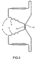
- fig. 3 shows the cross-section of one of the bar ends, along the line III-III shown in fig. 1.
- the bumper bar that is shown in fig. 1 is to be mounted horizontally at the front end of a vehicle, at the front ends of the side bars of the vehicle.
- the mounting of the bumper at the side bars takes place with a freely chosen method.
- the bumper bar has been mounted onto the vehicle, its main task is to meet, distribute and dissipate the energy that is absorbed during a collision between the vehicle and another object.
- the bar should mainly take care of those forces that act on the vehicle during a collision directly from the front or obliquely from the front.
- the front end of the vehicle will provide a direction indicator.
- the word “forwards” will denote the direction in which the vehicle normally travels, and "backwards” will denote the opposite direction.
- the bar is formed from sheet metal, for example, steel. Boron steel gives a good result and is economically advantageous.
- the bar is extended in one dimension and shaped as a tube with a dosed cross-section (see fig. 1).
- the bar includes a front flange 1, a rear flange 2, a top side 3 and a bottom side 4 (see fig. 2).
- the flanges and the top and bottom sides comprise sections of one and the same piece of material and form the main limiting surfaces of the bar.
- the front flange 1 points forwards in the direction of the vehicle when the bar is mounted, and it comprises the first contact area between the bar and the collision object.
- the rear flange 2 makes it possible to fasten the bar at the front ends of the side bars of a vehicle.
- the flanges 1 and 2 and the top and bottom sides 3 and 4 are furnished with bends 5, grooves 6 and 7, or other similar shapings of the material, longitudinal and/or transverse relative to the long axis of the bar, affecting the energy-absorbing properties of the bar.
- the bar has an undivided open inner space at its central part, and it is here that it has its maximum volume, distributed around the main axis of the bar (see figs. 1 and 2).
- the central part of the bar has a large volume and a large amount of material in order to offer the best possible energy absorption during a collision.
- the shape of the bar changes at the ends in order to make the mounting of the bar onto the vehicle easier (see figs. 1 and 3).
- the change of shape has taken place in a controlled manner, for example in a forming tool.
- a longitudinal part 2.1 of the rear flange 2 is pressed in towards a longitudinal part 1.1 of the front flange 1.
- the longitudinal parts 1.1 and 2.1 constitute each a longitudinal central part of the two flanges 1 and 2. It is also possible to carry out the change of shape based on two or more longitudinal parts on each flange. Most of the rear flange 2, induding a boundary region between the top side 3 and the bottom side 4 and the rear flange 2, are pressed into the bar.
- the bar obtains two tube-formed parts 8 with an open inner part along a length X at both of its ends (see figs. 1 and 3).
- the bar in the boundary region between the top side 3 and the bottom side 4 and the rear flange 2 is furnished with longitudinal bends 5 providing guides for and facilitating the pressing.
- the rear flange 2 has longitudinal grooves 6 that act as pliable bellows during the pressing.
- the sheet metal material in the grooves 6 is drawn out during the pressing and contributes to reducing the occurrence of inner tensions in the material. In this way, the formation of cracks and weaknesses can be reduced.
- the rear flange 2 is depressed to such an extent that the inner surface of the longitudinal part 2.1 is brought into contact with the inner surface of the longitudinal part 1.1 of the front flange 1 (see fig. 3).
- the two flanges 1 and 2 are welded together along the stretch X.
- the front flange 1 has not had its shape altered by the pressing together, but has the same appearance along the full length of the bar.
- the front flange 1 is furnished in its longitudinal central part 1.1 with a longitudinal trench-shaped indentation 9.
- the rear flange also has a longitudinal trench-shaped indentation 10 in its longitudinal central part 2.1.
- the two indentations 9 and 10 are directed inwards into the central cavity of the bar, and both have a bottom part 9.1 and 10.1, respectively.
- the bottom part 9.1 of the indentation 9 in the front flange is, at the ends of the bar, in contact with the bottom part 10.1 of the indentation 10 in the rear flange.
- the welded joint is in principle as long as the stretch X, and the bar shows the two tube formations 8 along the stretch X. This pressing together and welding implies that the bar has different energy-absorbing: properties in this region than it has in its central part.
- the region of the welded joint constitutes a dear rotational guide for the bar during a collision. The bar will be more easily broken in this distinct region and in this way absorb large amounts of energy.
- the bar has its maximum volume at its central part and its minimum volume at the ends, to be more precise, in the region where the flanges are united by the welded joint
- the volume of the bar increases from the point where the welded joints terminate to its maximum volume at the centre of the bar.
- the bar is slightly curved (see fig. 1).
- the ends of the bar point partially or wholly backwards and in this way the bar more easily follows the rounded frontal shape of the front of a vehicle.
- the top side and the bottom side of the bar have transverse grooves 7 in order to facilitate the bending of the bar.
- the grooves 7 act as bellows and are drawn out during the bending of the bar.
- the grooves 7 can also function as bending guides.
- the surplus sheet metal material in the grooves 7 is drawn out during the bending and this contributes to reducing the occurrence of inner tensions in the material.
- the formation of cracks and weaknesses can be minimised.
- the pressing together of the rear flange 2 against the front flange 1 facilitates the bending of the ends of the bar since the width B of the bar is reduced and the bar thus acquires a reduced resistance to bending.
- the bar has a constant height H and a varying width B along its complete length (see fig. 1).
- the bar has its maximal width at the central part and its minimum width at the ends. It is, of course, possible to form the bar with its construction of bends and grooves in a similar way along its complete length.
- the external dimensions of the bar after the pressing are always equal to or less than they were in the initial state of the bar. The bar becomes neither longer, wider or higher at any part of its extent. Nor is the bar exposed to any reduction of material that would lead to weakening.
- the bumper bar satisfies the demands for durability that are posed on a bar of this type and the demands that exist concerning appearance, adaptability and, not least, cost-efficiency.
- the bumper bar makes it possible to manufacture vehicles that are safe in traffic within the strict technical and economic demands that exist in the vehicle industry.
- the method for manufacturing the bumper bar is commenced by feeding a flat sheet into a roll-forming device.
- the sheet is shaped into a tubular extended element with a dosed cross-section in the roll-forming device.
- the closed cross-section is obtained by welding together by spot welding, seam welding, or a similar method, the edges of the plate, which after the roll-forming meet and make contact with each other.
- the roll-forming device can shape bends 5, longitudinal grooves 6 and transverse grooves 7 in the sheet in order to make the further shaping of the bar possible, and also to improve the final torsional rigidity, flexural rigidity and other properties of the bar that take up forces during a collision.
- the sheet Before the roll-forming is commenced, the sheet can be cut into suitable lengths, which ensures that the final length of the bumper bar is as desired. The sheet can also be cut after the roll-forming operation.
- the bar is placed in an oven and heated to a suitable austenitizing temperature for the material.
- a suitable temperature for boron steel lies around 900 °C.
- the longitudinal central part 2.1 of the rear flange is pushed in towards the longitudinal central part 1.1 of the front flange in the forming tool, whereby the width B, the so-called building height, of the bumper bar is reduced.
- This inwards pressing mainly takes place at the ends of the bumper bar, from that region of the bar that is to be fixed to the side bars of the vehicle and outwards, approximately along the stretch X shown in Figure 1.
- the bar has received bends 5 that act as guides to facilitate the pressing together.
- the rear flange 2 is also furnished with longitudinal grooves 6 which are drawn out as a bellow during this pressing in of the rear flange, and facilitate the shaping. The risk for extension of the material and tension that arises from it is minimised.
- the pressing together is complete in a centred part of the cross-section of the bar at the very end of the furthest part of the bar, so that the two flanges 1 and 2 come into contact with each other. It is an advantage if the flanges 1 and 2 of the bumper bar are welded together where the inner surfaces of the flanges meet each other after the pressing together, along the stretch X. The welded joint will constitute a dear rotation- and breakage guide during a collision, to take care of the collision forces.
- the bumper bar is shaped along its horizontal extension by bending.
- the bar is completely straight when it comes out from the roll-forming device.
- the front of a vehicle is often bent backwards out towards the sides of the vehicle in order to reduce air resistance, to improve the properties of the vehicle for absorbing collision forces and to make the appearance attractive.
- the bumper bar should have an equivalent bending in order to optimise the use of available space.
- the ends of the bar are bent backwards with the same forming tool that carries out the pressing together.
- the bar has been furnished with transverse grooves 7 on the top side 3 and the bottom side 4, which facilitate this bending.
- the grooves 7 are drawn out as a bellow and the risk for extension of the material and tension that arises from it is thus minimised.
- the pressing together of the rear flange 2 against the front flange 1 facilitates the bending of the bar since the width B of the bar and thus its flexural rigidity have been reduced at the end parts of the bar.
- the bumper bar is quenched, still located in the forming tool.
- This method gives a bumper bar that is constructed in one piece and that only requires one roll-forming device and only one further forming device, which shapes the details and at the same time provides the bar with stability during quenching.
- the manufacture of vehicles that are safe in traffic becomes cost-efficient and of high quality.
Landscapes
- Engineering & Computer Science (AREA)
- Mechanical Engineering (AREA)
- Body Structure For Vehicles (AREA)
- Vibration Dampers (AREA)
- Casting Or Compression Moulding Of Plastics Or The Like (AREA)
- Bending Of Plates, Rods, And Pipes (AREA)
- Processing And Handling Of Plastics And Other Materials For Molding In General (AREA)
Abstract
Description
Claims (10)
- Bumper bar for vehicles where the bar is extended in one dimension, has two ends and a closed cross-section and includes at least one front flange (1) facing forwards in the normal direction of motion of the vehicle, one rear flange (2) facing the vehicle, one top side (3) and one bottom side (4), at least one part (2.1) of the rear flange (2) being pressed in towards at least one part (1.1) of the front flange (1), both these parts (2.1, 1.1) lying along the bar, characterised in that the pressing in is complete over a definite and limited stretch (X) extending from each end of the bar towards the longitudinal centre of the bar so that the inner surfaces of the parts (1.1, 2.1) of the front and rear flanges (1,2) make contact with each other along said definite and limited stretches (X) and in that in the longitudinal central part of the bar the pressing in is only partial so that the bar has its maximum volume at its longitudinal central part and its minimum volume along the definite and limited stretches (X) at the ends.
- Bumper bar according to claim 1 characterised in that the front and rear flanges (1, 2) are joined to each other along said limited stretches (X) along said part (1.1) of the front flange (1) and said part (2.1) of the rear flange (2) that lie along the bar whereby at least two tube-formed parts (8) with an open inner part are obtained along each stretch (X).
- Bumper bar according to claim 1 or 2 characterised in that the said part (1.1) of the front flange (1) and said part (2.1) of the rear flange (2) that lie along the bar constitute each respectively a central part of one of the two flanges (1, 2).
- Bumper bar according to any of claims 1-3 characterised in that the bar is furnished, in the region around the part (2.1) of the rear flange (2) that lies along the bar, with bends (5) that lie along the bar and that constitute guides to facilitate the pressing in.
- Bumper bar according to any of claims 1-4 characterised in that the bar is furnished, in the region around the part (2.1) of the rear flange (2) that lies along the bar, with grooves (6) that lie along the bar and that exhibit properties similar to those of a bellows during the pressing in.
- Bumper bar according to any of claims 1-5 characterised in that the bar is bent.
- Bumper bar according to claim 6 characterised in that the top side (3) and the bottom side (4) of the bar have grooves (7) running transverse to the bar and that behave as a bellows during the bending.
- Method for manufacturing a bumper bar of the type specified in claim 1 wherein the bar is heated after initial forming of the front and rear flanges (1, 2) and the top side (3) and the bottom side (4) to a chosen austenitizing temperature, based on the choice of material of the bar, and thereafter shaped in a forming tool and wherein at least one part (2.1) of the rear flange (2) is pressed in towards at least one part (1.1) of the front flange, both these parts (2.1, 1.1) lying along the bar, characterised in that the pressing in is complete over a definite and limited stretch (X) extending from each end of the bar towards the longitudinal centre of the bar so that the inner surfaces of the parts (1.1, 2.1) of the front and rear flanges (1, 2) make contact with each other along said definite and limited stretches (X) and in that in the longitudinal central part of the bar the pressing in is only partial so that the bar has its maximum volume at said longitudinal central part and its minimum volume along the definite and limited stretches (X) at the ends.
- Method according to claim 8 characterised in that a bending of the bar is initiated and facilitated by the pressing in of said at least one part (2.1) of the rear flange (2) towards said at least one part (1.1) of the front flange (1) and that further shaping is determined by the forming tool.
- Method according to claim 8 or claim 9 characterised in that the bar after shaping is quenched in the forming tool.
Applications Claiming Priority (3)
| Application Number | Priority Date | Filing Date | Title |
|---|---|---|---|
| SE9904566 | 1999-12-14 | ||
| SE9904566A SE516762C2 (en) | 1999-12-14 | 1999-12-14 | Bumper beam and method of manufacturing the same |
| PCT/SE2000/002308 WO2001044018A1 (en) | 1999-12-14 | 2000-11-23 | Bumper bar and method for manufacturing the same |
Publications (2)
| Publication Number | Publication Date |
|---|---|
| EP1237755A1 EP1237755A1 (en) | 2002-09-11 |
| EP1237755B1 true EP1237755B1 (en) | 2004-08-11 |
Family
ID=20418114
Family Applications (1)
| Application Number | Title | Priority Date | Filing Date |
|---|---|---|---|
| EP00986091A Expired - Lifetime EP1237755B1 (en) | 1999-12-14 | 2000-11-23 | Bumper bar and method for manufacturing the same |
Country Status (8)
| Country | Link |
|---|---|
| US (2) | US6352297B1 (en) |
| EP (1) | EP1237755B1 (en) |
| JP (1) | JP4582987B2 (en) |
| KR (1) | KR100732780B1 (en) |
| AT (1) | ATE273152T1 (en) |
| DE (1) | DE60012974T2 (en) |
| SE (1) | SE516762C2 (en) |
| WO (1) | WO2001044018A1 (en) |
Families Citing this family (54)
| Publication number | Priority date | Publication date | Assignee | Title |
|---|---|---|---|---|
| US6397550B1 (en) * | 1999-11-12 | 2002-06-04 | Steven H. Walker | Metal structural member |
| SE516760C2 (en) | 1999-12-14 | 2002-02-26 | Accra Teknik Ab | Bumper beam |
| JP4368483B2 (en) * | 2000-02-28 | 2009-11-18 | 富士重工業株式会社 | Bumper beam structure |
| DE10013527A1 (en) * | 2000-03-20 | 2001-10-11 | Benteler Werke Ag | Steel transverse bumper (fender) cross-bearer making process involves joining narrow strips into bonded element and deforming it by roll deforming process |
| US6540276B2 (en) * | 2000-11-09 | 2003-04-01 | Aisin Seiki Kabushiki Kaisha | Bumper reinforcement structure |
| DE60206398T2 (en) | 2001-07-02 | 2006-07-06 | Meridian Automative Systems, Inc., Dearborn | PUNCHED AND FOLDED BUMPER ROD |
| SE523371C2 (en) * | 2001-08-31 | 2004-04-13 | Accra Teknik Ab | Beam |
| US7407219B2 (en) * | 2004-03-24 | 2008-08-05 | Shape Corporation | Energy management beam |
| DE10226756B4 (en) * | 2002-06-14 | 2006-08-17 | Benteler Automobiltechnik Gmbh | Bumper for a motor vehicle |
| US6910721B2 (en) * | 2002-12-20 | 2005-06-28 | Pullman Industries, Inc. | Elongated bumper bar with sections twisted rotationally about the axis of elongation |
| US7066525B2 (en) * | 2003-02-25 | 2006-06-27 | Pullman Industries, Inc. | Wishbone shaped vehicle bumper beam |
| DE10327008B3 (en) * | 2003-06-12 | 2005-01-13 | Benteler Automobiltechnik Gmbh | Bumper for a motor vehicle |
| KR100527125B1 (en) * | 2003-06-19 | 2005-11-09 | 현대자동차주식회사 | Back Beam Structure of Automobile Bumper |
| US6923482B2 (en) | 2003-06-27 | 2005-08-02 | Magna International Inc. | Multiple material bumper beam |
| US7077439B2 (en) * | 2003-08-25 | 2006-07-18 | General Motors Corporation | Vehicle bumper and method of making same |
| US7503116B2 (en) * | 2004-01-20 | 2009-03-17 | Noble Advanced Technologies, Inc. | Continuous process for producing a shaped steel member |
| US7254977B2 (en) * | 2004-01-20 | 2007-08-14 | Pullman Industries, Inc. | Coolant delivery system and continuous fabrication apparatus which includes the system |
| US6948749B2 (en) * | 2004-01-26 | 2005-09-27 | Trim Trends Co., Llc | Cross member for vehicle bumper bar and method for making same |
| US7108303B2 (en) * | 2004-04-07 | 2006-09-19 | Pullman Industries, Inc. | Crushed profile bumper and method for producing |
| EP1755801B2 (en) * | 2004-05-13 | 2014-08-20 | Accra Teknik AB | A device and a method for shaping and quenching a beam |
| US6971691B1 (en) | 2004-06-25 | 2005-12-06 | Shape Corporation | Vehicle bumper beam |
| US6986536B1 (en) * | 2004-06-25 | 2006-01-17 | Shape Corporation | Vehicle bumper beam |
| US7163241B2 (en) * | 2004-06-25 | 2007-01-16 | F.Tech R&D North America Inc. | Vehicle bumper beam having non-uniform cross sections |
| US7197824B1 (en) | 2004-07-20 | 2007-04-03 | Trim Trends, Co., Llc | Cross member for vehicle bumper bar and method for making same |
| US20060028032A1 (en) * | 2004-08-06 | 2006-02-09 | Karl Henseleit | Vehicle bumper and method of making same |
| FR2883830B1 (en) * | 2005-03-30 | 2007-08-24 | Vallourec Vitry | BUMPER TRAVERSE FOR MOTOR VEHICLES, PRESERVING PEDESTRIANS |
| US7066508B1 (en) * | 2005-03-31 | 2006-06-27 | Ford Global Technologies, Llc | Bumper cross-section with hinges |
| US7210717B1 (en) | 2005-03-31 | 2007-05-01 | Ford Global Technologies, Llc | Lightweight bumper for automobiles |
| DE102005029738B4 (en) * | 2005-06-24 | 2018-10-04 | GM Global Technology Operations LLC (n. d. Ges. d. Staates Delaware) | Energy absorber element and this vehicle body using |
| JP4732055B2 (en) * | 2005-07-29 | 2011-07-27 | 株式会社神戸製鋼所 | Roll forming apparatus, roll forming method, and roll forming component |
| US7665778B2 (en) * | 2006-02-02 | 2010-02-23 | Karl Henseleit | Vehicle bumper and method of making same |
| US20080093867A1 (en) * | 2006-10-24 | 2008-04-24 | Shape Corporation | B-shaped beam with integrally-formed rib in face |
| US7891155B2 (en) * | 2007-02-15 | 2011-02-22 | Surowiecki Matt F | Sheet metal header beam |
| JP4546496B2 (en) * | 2007-03-09 | 2010-09-15 | 株式会社丸順 | Bumper beam for automobile |
| US7503601B2 (en) | 2007-05-31 | 2009-03-17 | Shape Corp. | B-shaped beam with radiused face but recessed center |
| KR100946258B1 (en) * | 2007-12-17 | 2010-03-09 | 한화엘앤씨 주식회사 | Car Reverse See-Type Bumper Beam |
| US7866716B2 (en) * | 2008-04-08 | 2011-01-11 | Flex-N-Gate Corporation | Energy absorber for vehicle |
| EP2279097B1 (en) * | 2008-04-10 | 2013-04-03 | Accra Teknik AB | Energy absorbing beam with controlled crush characteristics |
| SE532302C2 (en) * | 2008-04-24 | 2009-12-08 | Gestamp Hardtech Ab | Impact guard beam |
| JP2010083381A (en) * | 2008-09-30 | 2010-04-15 | Kobe Steel Ltd | Bumper system and method for manufacturing the same |
| JP5177417B2 (en) * | 2008-11-14 | 2013-04-03 | 株式会社神戸製鋼所 | Bumper structure and method for manufacturing bumper structure |
| US20100122981A1 (en) * | 2008-11-18 | 2010-05-20 | Evironmental Packaging Technologies Limited | Shipping container systems |
| EP2352662A4 (en) * | 2008-12-04 | 2016-12-21 | Benteler Automobiltechnik Gmbh | Impact absorbing member and a method for making same |
| JP5543756B2 (en) * | 2009-11-05 | 2014-07-09 | アイシン精機株式会社 | Bumper device for vehicle |
| JP5237252B2 (en) * | 2009-12-22 | 2013-07-17 | 株式会社神戸製鋼所 | Automotive bumper structure |
| US8205921B2 (en) * | 2010-02-25 | 2012-06-26 | Ford Global Technologies, Llc | Extruded aluminum bumper having triggers |
| DE102010035619B4 (en) * | 2010-08-26 | 2022-04-07 | Benteler Automobiltechnik Gmbh | Motor vehicle with a deformation element |
| CN104148539B (en) * | 2010-09-23 | 2016-02-10 | 形状集团 | The method of the multitube reinforcement rolling and forming for vehicle and roll forming machine |
| DE102012106249B4 (en) * | 2012-07-11 | 2018-10-31 | Dura Automotive Holdings U.K., Ltd. | bumper profile |
| KR101424529B1 (en) * | 2012-11-26 | 2014-08-01 | 주식회사 성우하이텍 | Bumper beam for vehicles |
| KR101435418B1 (en) * | 2012-11-26 | 2014-08-29 | 주식회사 성우하이텍 | Bumper beam for vehicles |
| US10065587B2 (en) | 2015-11-23 | 2018-09-04 | Flex|N|Gate Corporation | Multi-layer energy absorber |
| DE102016112344A1 (en) * | 2016-07-06 | 2018-01-11 | Benteler Automobiltechnik Gmbh | Reinforcement device for a motor vehicle door |
| CN118434600A (en) * | 2022-01-20 | 2024-08-02 | 日本制铁株式会社 | Open section bumper reinforcement |
Family Cites Families (36)
| Publication number | Priority date | Publication date | Assignee | Title |
|---|---|---|---|---|
| US3698224A (en) * | 1970-11-16 | 1972-10-17 | Siderurgica Occidental C A | Process for the production of steel structural shapes |
| US3851909A (en) * | 1972-03-24 | 1974-12-03 | Dura Corp | Vehicle bumper construction and method of making same |
| US4597601A (en) * | 1985-03-18 | 1986-07-01 | Transpec, Inc. | Energy absorbing vehicle bumper |
| US4652032A (en) * | 1985-10-16 | 1987-03-24 | Borg-Warner Chemicals, Inc. | Vehicle bumper assembly |
| JP2727201B2 (en) * | 1988-09-03 | 1998-03-11 | マツダ株式会社 | Car bumper structure |
| FR2653723B1 (en) * | 1989-11-02 | 1992-01-03 | Peugeot | BUMPER OF MOTOR VEHICLES COMPRISING ENERGY ABSORPTION MEANS. |
| US5395036A (en) * | 1990-03-26 | 1995-03-07 | Shape Corporation | Method of roll-forming an end automotive bumper |
| US5306058A (en) | 1990-03-26 | 1994-04-26 | Shape Corporation | Tubular roll-formed automotive bumper |
| US5104026A (en) * | 1990-03-26 | 1992-04-14 | Shape Corporation | Apparatus for roll-forming an automotive bumper |
| US5080412A (en) * | 1991-04-22 | 1992-01-14 | Chrysler Corporation | Vehicle and bumper beam combination |
| NO173538C (en) * | 1991-09-06 | 1993-12-29 | Norsk Hydro As | Construction beam and method of production of the same |
| JPH06247237A (en) | 1993-02-22 | 1994-09-06 | Nippon Steel Chem Co Ltd | Vehicle bumper and manufacturing method thereof |
| JPH072033A (en) * | 1993-06-16 | 1995-01-06 | Kobe Steel Ltd | Reinforcement structure for bumper of automobile |
| US5340178A (en) * | 1993-11-12 | 1994-08-23 | Chrysler Corporation | Vehicle bumper beam |
| US5425561A (en) * | 1993-12-21 | 1995-06-20 | General Motors Corporation | Flexible insert for an automotive bumper |
| JPH07205732A (en) * | 1994-01-13 | 1995-08-08 | Yamakawa Ind Co Ltd | Bumper reinforcement and its manufacturing method |
| SE503450C2 (en) * | 1994-01-26 | 1996-06-17 | Plannja Hardtech Ab | Bumper beam |
| JP2772621B2 (en) | 1994-09-30 | 1998-07-02 | 本田技研工業株式会社 | Bumper beam |
| US5498045A (en) * | 1994-12-14 | 1996-03-12 | General Motors Corporation | Blow molded bumper beam and U-bolt attachment |
| DE19509541A1 (en) * | 1995-03-16 | 1996-09-19 | Bayerische Motoren Werke Ag | Motor vehicle bumper with fixed, transverse retaining part |
| JP3120957B2 (en) * | 1995-07-07 | 2000-12-25 | 本田技研工業株式会社 | Manufacturing method of bumper beam for vehicle |
| JPH09141329A (en) * | 1995-11-20 | 1997-06-03 | Aisin Seiki Co Ltd | Manufacturing method of reinforcing member of vehicle bumper device |
| NO960288D0 (en) * | 1996-01-24 | 1996-01-24 | Raufoss Automotive As | Stötfangerskinne |
| FR2756524B1 (en) * | 1996-11-29 | 1999-01-08 | Renault | ENERGY ABSORBING BUMPER FOR VEHICLES |
| DE19726720C1 (en) * | 1997-06-24 | 1998-10-08 | Daimler Benz Ag | Hollow body section e.g. for motor vehicle door and bumper reinforcement element |
| US6042163A (en) * | 1998-01-28 | 2000-03-28 | Shape Corporation | Vehicle bumper including end section and method of manufacture |
| US6000738A (en) * | 1998-03-13 | 1999-12-14 | Chrysler Corporation | Force-absorbing vehicle bumper |
| US5997057A (en) * | 1998-04-16 | 1999-12-07 | Chrysler Corporation | Bumper end cap |
| US6082792A (en) * | 1998-05-07 | 2000-07-04 | General Electric Company | Vehicle bumper |
| US6240820B1 (en) * | 1998-05-19 | 2001-06-05 | Shape Corporation | Die apparatus for cutting end of bumper bar |
| ATE253477T1 (en) * | 1998-07-29 | 2003-11-15 | Conix Corp | BUMPER BEAM EXTENSIONS |
| ATE259315T1 (en) * | 1998-09-18 | 2004-02-15 | Cosma Int Inc | METHOD FOR PRODUCING A BUMPER ASSEMBLY |
| US6349521B1 (en) * | 1999-06-18 | 2002-02-26 | Shape Corporation | Vehicle bumper beam with non-uniform cross section |
| US6477774B1 (en) * | 1999-09-30 | 2002-11-12 | Dana Corporation | Method of manufacturing a vehicle frame assembly |
| JP3623916B2 (en) * | 1999-11-11 | 2005-02-23 | アイシン軽金属株式会社 | Bumper reinforcement |
| US6485072B1 (en) * | 1999-12-15 | 2002-11-26 | Ford Global Technologies, Inc. | Bumper system for motor vehicles |
-
1999
- 1999-12-14 SE SE9904566A patent/SE516762C2/en not_active IP Right Cessation
-
2000
- 2000-05-09 US US09/567,846 patent/US6352297B1/en not_active Expired - Lifetime
- 2000-11-23 KR KR1020027007486A patent/KR100732780B1/en not_active Expired - Fee Related
- 2000-11-23 AT AT00986091T patent/ATE273152T1/en not_active IP Right Cessation
- 2000-11-23 DE DE60012974T patent/DE60012974T2/en not_active Expired - Lifetime
- 2000-11-23 WO PCT/SE2000/002308 patent/WO2001044018A1/en not_active Ceased
- 2000-11-23 EP EP00986091A patent/EP1237755B1/en not_active Expired - Lifetime
- 2000-11-23 JP JP2001545124A patent/JP4582987B2/en not_active Expired - Fee Related
-
2001
- 2001-08-08 US US09/924,429 patent/US6684505B2/en not_active Expired - Lifetime
Also Published As
| Publication number | Publication date |
|---|---|
| EP1237755A1 (en) | 2002-09-11 |
| SE9904566D0 (en) | 1999-12-14 |
| US6352297B1 (en) | 2002-03-05 |
| US6684505B2 (en) | 2004-02-03 |
| SE9904566L (en) | 2001-06-15 |
| DE60012974D1 (en) | 2004-09-16 |
| US20010054827A1 (en) | 2001-12-27 |
| JP2003516902A (en) | 2003-05-20 |
| KR100732780B1 (en) | 2007-06-27 |
| WO2001044018A1 (en) | 2001-06-21 |
| JP4582987B2 (en) | 2010-11-17 |
| SE516762C2 (en) | 2002-02-26 |
| ATE273152T1 (en) | 2004-08-15 |
| KR20020069209A (en) | 2002-08-29 |
| DE60012974T2 (en) | 2005-08-11 |
Similar Documents
| Publication | Publication Date | Title |
|---|---|---|
| EP1237755B1 (en) | Bumper bar and method for manufacturing the same | |
| KR100354408B1 (en) | Bumper structure | |
| JP5543756B2 (en) | Bumper device for vehicle | |
| US7108303B2 (en) | Crushed profile bumper and method for producing | |
| US6591577B2 (en) | Automobile door reinforcing member | |
| US7731272B2 (en) | A-pillar force transfer structure | |
| EP1237754B1 (en) | Bumper bar | |
| KR20010074963A (en) | Bumper beam for motor vehicles | |
| US20060028032A1 (en) | Vehicle bumper and method of making same | |
| CN112158157A (en) | Double-central-support-leg tubular beam and forming method thereof | |
| KR102128690B1 (en) | Bumper beam with 8-shaped cross section | |
| KR20190067868A (en) | A bumper beam with ribs on the walls of the bumper beam | |
| US7066525B2 (en) | Wishbone shaped vehicle bumper beam | |
| JP2008120227A (en) | Method for manufacturing shock absorber for vehicle | |
| US6910721B2 (en) | Elongated bumper bar with sections twisted rotationally about the axis of elongation | |
| CN212682130U (en) | A double-center outrigger tube beam and an automobile anti-collision beam forming device | |
| EP1262374B1 (en) | Crash energy absorbing element | |
| CN212685470U (en) | Double-central-support-leg tubular beam, automobile anti-collision beam and protection device | |
| US20240399987A1 (en) | Roll-formed vehicle structural beam with reinforcing insert | |
| CA2580597A1 (en) | Bumper with face-mounted reinforcer | |
| KR100676846B1 (en) | Door impact beam of vehicle and manufacturing method thereof | |
| EP1794033A1 (en) | Beam, and method for making such beam | |
| JP3842008B2 (en) | Vehicle door beam | |
| WO2024241410A1 (en) | Vehicle exterior mounting structure | |
| KR20050018632A (en) | Blank, chassis component and method for production of said chassis component |
Legal Events
| Date | Code | Title | Description |
|---|---|---|---|
| PUAI | Public reference made under article 153(3) epc to a published international application that has entered the european phase |
Free format text: ORIGINAL CODE: 0009012 |
|
| 17P | Request for examination filed |
Effective date: 20020523 |
|
| AK | Designated contracting states |
Kind code of ref document: A1 Designated state(s): AT BE CH CY DE DK ES FI FR GB GR IE IT LI LU MC NL PT SE TR |
|
| 17Q | First examination report despatched |
Effective date: 20030411 |
|
| GRAP | Despatch of communication of intention to grant a patent |
Free format text: ORIGINAL CODE: EPIDOSNIGR1 |
|
| GRAS | Grant fee paid |
Free format text: ORIGINAL CODE: EPIDOSNIGR3 |
|
| GRAA | (expected) grant |
Free format text: ORIGINAL CODE: 0009210 |
|
| AK | Designated contracting states |
Kind code of ref document: B1 Designated state(s): AT BE CH CY DE DK ES FI FR GB GR IE IT LI LU MC NL PT SE TR |
|
| PG25 | Lapsed in a contracting state [announced via postgrant information from national office to epo] |
Ref country code: IT Free format text: LAPSE BECAUSE OF FAILURE TO SUBMIT A TRANSLATION OF THE DESCRIPTION OR TO PAY THE FEE WITHIN THE PRE;WARNING: LAPSES OF ITALIAN PATENTS WITH EFFECTIVE DATE BEFORE 2007 MAY HAVE OCCURRED AT ANY TIME BEFORE 2007. THE CORRECT EFFECTIVE DATE MAY BE DIFFERENT FROM THE ONE RECORDED.SCRIBED TIME-LIMIT Effective date: 20040811 Ref country code: NL Free format text: LAPSE BECAUSE OF FAILURE TO SUBMIT A TRANSLATION OF THE DESCRIPTION OR TO PAY THE FEE WITHIN THE PRESCRIBED TIME-LIMIT Effective date: 20040811 Ref country code: ES Free format text: LAPSE BECAUSE OF FAILURE TO SUBMIT A TRANSLATION OF THE DESCRIPTION OR TO PAY THE FEE WITHIN THE PRESCRIBED TIME-LIMIT Effective date: 20040811 Ref country code: LI Free format text: LAPSE BECAUSE OF FAILURE TO SUBMIT A TRANSLATION OF THE DESCRIPTION OR TO PAY THE FEE WITHIN THE PRESCRIBED TIME-LIMIT Effective date: 20040811 Ref country code: CH Free format text: LAPSE BECAUSE OF FAILURE TO SUBMIT A TRANSLATION OF THE DESCRIPTION OR TO PAY THE FEE WITHIN THE PRESCRIBED TIME-LIMIT Effective date: 20040811 Ref country code: AT Free format text: LAPSE BECAUSE OF FAILURE TO SUBMIT A TRANSLATION OF THE DESCRIPTION OR TO PAY THE FEE WITHIN THE PRESCRIBED TIME-LIMIT Effective date: 20040811 Ref country code: FI Free format text: LAPSE BECAUSE OF FAILURE TO SUBMIT A TRANSLATION OF THE DESCRIPTION OR TO PAY THE FEE WITHIN THE PRESCRIBED TIME-LIMIT Effective date: 20040811 Ref country code: CY Free format text: LAPSE BECAUSE OF FAILURE TO SUBMIT A TRANSLATION OF THE DESCRIPTION OR TO PAY THE FEE WITHIN THE PRESCRIBED TIME-LIMIT Effective date: 20040811 Ref country code: BE Free format text: LAPSE BECAUSE OF FAILURE TO SUBMIT A TRANSLATION OF THE DESCRIPTION OR TO PAY THE FEE WITHIN THE PRESCRIBED TIME-LIMIT Effective date: 20040811 Ref country code: TR Free format text: LAPSE BECAUSE OF FAILURE TO SUBMIT A TRANSLATION OF THE DESCRIPTION OR TO PAY THE FEE WITHIN THE PRESCRIBED TIME-LIMIT Effective date: 20040811 |
|
| REG | Reference to a national code |
Ref country code: GB Ref legal event code: FG4D |
|
| RIN1 | Information on inventor provided before grant (corrected) |
Inventor name: SUNDGREN, ANDERS Inventor name: BERGLUND, GOERAN Inventor name: LINDBERG, MATS |
|
| REG | Reference to a national code |
Ref country code: CH Ref legal event code: EP |
|
| REG | Reference to a national code |
Ref country code: IE Ref legal event code: FG4D |
|
| REF | Corresponds to: |
Ref document number: 60012974 Country of ref document: DE Date of ref document: 20040916 Kind code of ref document: P |
|
| PG25 | Lapsed in a contracting state [announced via postgrant information from national office to epo] |
Ref country code: SE Free format text: LAPSE BECAUSE OF FAILURE TO SUBMIT A TRANSLATION OF THE DESCRIPTION OR TO PAY THE FEE WITHIN THE PRESCRIBED TIME-LIMIT Effective date: 20041111 Ref country code: GR Free format text: LAPSE BECAUSE OF FAILURE TO SUBMIT A TRANSLATION OF THE DESCRIPTION OR TO PAY THE FEE WITHIN THE PRESCRIBED TIME-LIMIT Effective date: 20041111 Ref country code: DK Free format text: LAPSE BECAUSE OF FAILURE TO SUBMIT A TRANSLATION OF THE DESCRIPTION OR TO PAY THE FEE WITHIN THE PRESCRIBED TIME-LIMIT Effective date: 20041111 |
|
| PG25 | Lapsed in a contracting state [announced via postgrant information from national office to epo] |
Ref country code: LU Free format text: LAPSE BECAUSE OF NON-PAYMENT OF DUE FEES Effective date: 20041123 Ref country code: IE Free format text: LAPSE BECAUSE OF NON-PAYMENT OF DUE FEES Effective date: 20041123 |
|
| PG25 | Lapsed in a contracting state [announced via postgrant information from national office to epo] |
Ref country code: MC Free format text: LAPSE BECAUSE OF NON-PAYMENT OF DUE FEES Effective date: 20041130 |
|
| NLV1 | Nl: lapsed or annulled due to failure to fulfill the requirements of art. 29p and 29m of the patents act | ||
| REG | Reference to a national code |
Ref country code: CH Ref legal event code: PL |
|
| PLBE | No opposition filed within time limit |
Free format text: ORIGINAL CODE: 0009261 |
|
| STAA | Information on the status of an ep patent application or granted ep patent |
Free format text: STATUS: NO OPPOSITION FILED WITHIN TIME LIMIT |
|
| ET | Fr: translation filed | ||
| 26N | No opposition filed |
Effective date: 20050512 |
|
| REG | Reference to a national code |
Ref country code: IE Ref legal event code: MM4A |
|
| PG25 | Lapsed in a contracting state [announced via postgrant information from national office to epo] |
Ref country code: PT Free format text: LAPSE BECAUSE OF NON-PAYMENT OF DUE FEES Effective date: 20050111 |
|
| PGFP | Annual fee paid to national office [announced via postgrant information from national office to epo] |
Ref country code: FR Payment date: 20141119 Year of fee payment: 15 Ref country code: DE Payment date: 20141130 Year of fee payment: 15 Ref country code: GB Payment date: 20141119 Year of fee payment: 15 |
|
| REG | Reference to a national code |
Ref country code: DE Ref legal event code: R082 Ref document number: 60012974 Country of ref document: DE Representative=s name: DR. MUELLER PATENTANWAELTE, DE |
|
| REG | Reference to a national code |
Ref country code: DE Ref legal event code: R082 Ref document number: 60012974 Country of ref document: DE Representative=s name: DR. MUELLER PATENTANWAELTE, DE |
|
| REG | Reference to a national code |
Ref country code: DE Ref legal event code: R119 Ref document number: 60012974 Country of ref document: DE |
|
| GBPC | Gb: european patent ceased through non-payment of renewal fee |
Effective date: 20151123 |
|
| REG | Reference to a national code |
Ref country code: FR Ref legal event code: ST Effective date: 20160729 |
|
| PG25 | Lapsed in a contracting state [announced via postgrant information from national office to epo] |
Ref country code: GB Free format text: LAPSE BECAUSE OF NON-PAYMENT OF DUE FEES Effective date: 20151123 Ref country code: DE Free format text: LAPSE BECAUSE OF NON-PAYMENT OF DUE FEES Effective date: 20160601 |
|
| PG25 | Lapsed in a contracting state [announced via postgrant information from national office to epo] |
Ref country code: FR Free format text: LAPSE BECAUSE OF NON-PAYMENT OF DUE FEES Effective date: 20151130 |