EP1237249B9 - Schutzrelais - Google Patents
Schutzrelais Download PDFInfo
- Publication number
- EP1237249B9 EP1237249B9 EP02004755A EP02004755A EP1237249B9 EP 1237249 B9 EP1237249 B9 EP 1237249B9 EP 02004755 A EP02004755 A EP 02004755A EP 02004755 A EP02004755 A EP 02004755A EP 1237249 B9 EP1237249 B9 EP 1237249B9
- Authority
- EP
- European Patent Office
- Prior art keywords
- data
- voltage
- current
- current data
- value
- Prior art date
- Legal status (The legal status is an assumption and is not a legal conclusion. Google has not performed a legal analysis and makes no representation as to the accuracy of the status listed.)
- Expired - Lifetime
Links
- 230000014509 gene expression Effects 0.000 claims description 67
- 238000012546 transfer Methods 0.000 claims description 30
- 238000005070 sampling Methods 0.000 claims description 27
- 238000004364 calculation method Methods 0.000 claims description 20
- 230000005540 biological transmission Effects 0.000 claims description 13
- 230000005611 electricity Effects 0.000 claims description 12
- 238000006243 chemical reaction Methods 0.000 claims description 10
- 238000005259 measurement Methods 0.000 claims description 6
- 230000035945 sensitivity Effects 0.000 claims description 5
- 238000010586 diagram Methods 0.000 description 20
- 238000000034 method Methods 0.000 description 9
- 230000003321 amplification Effects 0.000 description 8
- 238000003199 nucleic acid amplification method Methods 0.000 description 8
- 238000012986 modification Methods 0.000 description 5
- 230000004048 modification Effects 0.000 description 5
- 239000000284 extract Substances 0.000 description 3
- 230000010354 integration Effects 0.000 description 3
- 238000013016 damping Methods 0.000 description 2
- 230000003111 delayed effect Effects 0.000 description 2
- 238000009434 installation Methods 0.000 description 2
- 101100042630 Caenorhabditis elegans sin-3 gene Proteins 0.000 description 1
- 239000003990 capacitor Substances 0.000 description 1
- 238000007796 conventional method Methods 0.000 description 1
- 230000007423 decrease Effects 0.000 description 1
- 230000003247 decreasing effect Effects 0.000 description 1
- 238000001514 detection method Methods 0.000 description 1
- 230000000694 effects Effects 0.000 description 1
- 230000001939 inductive effect Effects 0.000 description 1
- 230000002035 prolonged effect Effects 0.000 description 1
- 230000001681 protective effect Effects 0.000 description 1
- 238000013139 quantization Methods 0.000 description 1
Images


Classifications
-
- H—ELECTRICITY
- H02—GENERATION; CONVERSION OR DISTRIBUTION OF ELECTRIC POWER
- H02H—EMERGENCY PROTECTIVE CIRCUIT ARRANGEMENTS
- H02H3/00—Emergency protective circuit arrangements for automatic disconnection directly responsive to an undesired change from normal electric working condition with or without subsequent reconnection ; integrated protection
- H02H3/02—Details
-
- H—ELECTRICITY
- H02—GENERATION; CONVERSION OR DISTRIBUTION OF ELECTRIC POWER
- H02H—EMERGENCY PROTECTIVE CIRCUIT ARRANGEMENTS
- H02H3/00—Emergency protective circuit arrangements for automatic disconnection directly responsive to an undesired change from normal electric working condition with or without subsequent reconnection ; integrated protection
- H02H3/40—Emergency protective circuit arrangements for automatic disconnection directly responsive to an undesired change from normal electric working condition with or without subsequent reconnection ; integrated protection responsive to ratio of voltage and current
-
- H—ELECTRICITY
- H02—GENERATION; CONVERSION OR DISTRIBUTION OF ELECTRIC POWER
- H02H—EMERGENCY PROTECTIVE CIRCUIT ARRANGEMENTS
- H02H1/00—Details of emergency protective circuit arrangements
- H02H1/0092—Details of emergency protective circuit arrangements concerning the data processing means, e.g. expert systems, neural networks
Definitions
- the present invention relates to a protection relay in which an influence of distortion component of fault current generated by a fault in a power system is suppressed.
- a protection relay is used to monitor a power system.
- a main technical subject of such a protection relay is to reduce an influence of harmonics in fault current and fault voltage generated in a fault in a system contained in a signal inputted from the system.
- filter delay time needs to be prolonged, so that relay operation time is delayed.
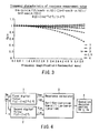
- L m /L (true value) is as expressed in the expression (4) under conditions of the expressions (5) and (6), so that frequency characteristic of X m /X (true value) is as indicated with the dotted curve of FIG. 2 .
- L m / L true value tan ⁇ 0 ⁇ T / 2 / tan ⁇ ⁇ T / 2
- i m Isin ⁇ ⁇ t m
- frequency characteristic of X m /X (true value) is as indicated with the dotted curve of FIG. 2 .
- FIG. 2 indicates that the value of ( ⁇ T/2) only should be suppressed to substantially 1 (that is, the sampling period should be set small) when this value (L m /L) is near twice or three times the fundamental wave.
- the value of the expression (7) is a very small value with respect to an amplitude value I. Therefore, a relative value of noise (quantization error generated at the time of A/D conversion, white noise generated in an analog circuit) contained in sampling data (i m , i m-1 ) is increased thereby disabling practical use of this method.
- EP 0 718 949 discloses a protection relay for determining whether or not a fault point of a power system exists in a predetermined range by using a trapezoidal integration approximation algorithm which can improve the accuracy by the fast sampling to the protective relay.
- An object of the present invention is to provide an improved protection relay.
- a protection relay for determining whether or not a faultal point of a power system exists in a predetermined range according to a first aspect of the present invention which is disclosed in claim 1.
- a protection relay for determining whether or not a faultal point of a power system exists in a predetermined range according to a second aspect of the present invention which is disclosed in claim 7.
- a protection relay for determining whether or not a faultal point of power system exists in a predetermined range according to a third aspect of the present invention which is disclosed in claim 9.
- Voltage can be obtained in the same manner as current and if it is assumed that the voltages are v sm and v jm , they are in such a relation that they are normal to each other.
- i jm , i sm , and v sm at time t m and i jm-1 , i sm-1 , and v sm-1 at time t m-1 are substituted for:
- Xm - v sm ⁇ i sm - p + i sm ⁇ v sm - p - i jm ⁇ i sm - p + i jm - p ⁇ i sm
- voltage v sm is provided in the form of:
- v sm V ⁇ k + 2 ⁇ cos ⁇ ⁇ T ⁇ ( sin n + 1 ⁇ ⁇ ⁇ T / 2 / sin ⁇ ⁇ T / 2 ⁇ sin ⁇ ⁇ t m + ⁇ - n + 2 ⁇ ⁇ ⁇ T / 2
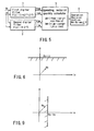
- FIG. 4 is a block diagram showing schematically the structure of the protection relay according to the first embodiment.
- the protection relay of the first embodiment suppresses amplification of the noise error contained in minute quantity of data even when the sampling period is shortened, in order to secure performance of frequency characteristic indicated in the expression (4).
- a first (digital) filter 1 comprises a digital filter (Z indicates a Z conversion operator) which outputs sampling data v m and i m about voltage v and current i of a power system as voltage data v sm and current data i sm through transfer function f(Z) ⁇ (1+k ⁇ Z -1 +Z -2 ) and extracts predetermined frequency components of voltage and current of a power system (not shown), which is a protecting object.
- Z indicates a Z conversion operator
- a second (digital) filter 2 comprises a digital filter (Z indicates a Z conversion operator) which outputs sampling data v m and i m as voltage data v jm and i jm through transfer function f(Z) ⁇ (1-Z -2 ) and extracts voltage and current normal to the first filter 1 in all frequency components.
- Z indicates a Z conversion operator
- a reactance value calculator 3 calculates a reactance value X m from voltage data v sm , current data i sm , voltage data v jm and voltage data i jm at time t m and voltage data i sm-p , current data i sm-p , voltage data v jm-p and current data i jm-p at time t m-p .
- An operation decision section 4 compares the reactance value X m obtained by the reactance calculator 3 with a preliminarily set integer (whether or not X m ⁇ X s is determined with X s ).
- the preliminarily set integer value is called setting value in this specification.
- the first filter having the transfer function f(Z) ⁇ (1+k ⁇ Z -1 +Z -2 ) receives input of sampling data v m and i m about voltage v and current i of the power system and outputs voltage data v sm and current data i sm .
- the second filter having the transfer function f(Z) ⁇ (1-Z -2 ) receives input of sampling data v m and i m about the voltage v and current i and outputs voltage data v jm and current data i jm .
- the reactance value calculator 3 calculates a reactance value X m from the voltage data v sm and current data i sm obtained by the first filter 1 and voltage data v jm and current data i jm obtained by the second filter 2 at time t m , and voltage data v sm-p and current data i sm-p obtained by the first filter 1 and voltage data v jm-p and current data i jm-p obtained by the second filter 2 at time t m-p according to the expression (17):
- Xm - v sm ⁇ i sm - p + i sm ⁇ v sm - p - i jm ⁇ i sm - p + i jm - p ⁇ i sm
- m and p represent sampling time series.
- the operation decision section 4 decides whether or not X m ⁇ X s is established from the reactance value X m and setting value X s obtained by the reactance value calculator 3 and when that relation is established, it decides it is active and otherwise, it decides it is inactive.
- the transfer functions of the first and second filters 1 and 2 are expressed in f(Z) ⁇ (1+k ⁇ Z -1 +Z -2 ) and f(Z) ⁇ (1-Z -2 ) when the Z conversion operator is employed.
- the outputs of the first and second filters 1 and 2 are normal to each other. There is a relation that the output of the first filter 1 is delayed at 90° with respect to the output of the second filter 2.
- transfer function 1 f(Z)
- transfer function 2 (1+k ⁇ Z -1 +Z -2 )
- transfer function 3 1-Z -2 and form the first filter 1 and the second filter 2 by combining those.
- the same output can be obtained by passing the input voltage and current through a digital filter of the transfer function 1 and then passing its output through digital filters of the transfer functions 2 and 3.
- the operation decision section 4 corrects the decision expression using the reactance value X m , setting value X s and preliminarily set fundamental wave constant sin ( ⁇ 0 T)/(k+2 ⁇ cos( ⁇ 0 T)) with respect to the reactance value X m calculated by the reactance value calculator 3 as indicated in the expression (18) so as to decide whether or not it is active.
- Such operation decision is carried out plural times ordinarily.
- the reactance value calculator 3 calculates the reactance value using outputs of the first filter 1 and the second filter 2 and the operation decision section 4 decides whether or not it is active according to the condition expression (18) based on that reactance value.
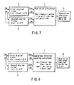
- an operating restarint quantity calculator 5 to calculate a m and b m according to the expression (19) based on the outputs of the first filter 1 and the second filter 2 and then for an operation decision section 6 to decide the operation according to the expression (20) to be described later using that result.
- a m - v m ⁇ i sm - p + v sm - p ⁇ i m
- b m - i jm ⁇ i sm - p + i jm - p ⁇ i sm
- the operation decision section 6 corrects sensitivity constant K 0 and reactance setting value X s to X s ⁇ X s /(sin( ⁇ 0 T)/(k+2 ⁇ cos( ⁇ 0 T)) using a m and b m outputted in this way and decides the operation according to a decision expression of the expression (21).
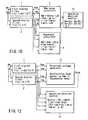
- Ohm value calculator 7 defined by expression (22) as shown in FIG. 7 as such calculation means or an operation decision section 8 defined by the expression (25), which will be described later.
- Xm - v sm ⁇ i sm - p + i sm ⁇ v sm - p - i jm ⁇ i sm - p + i jm - p ⁇ i sm
- the operation decision section 8 decides whether or not a decision expression for the expression (25) is established based on the Ohm value R m and the setting value R s calculated from the expression (24) and when that expression is established, it decides it is active.
- the operation decision section 10 decides whether or not it is active based on the decision expression (28) from c m , b m , Ohm setting value R s and sensitivity constant K l .
- Such protection relay has Ohm characteristic shown in FIG. 9 like the configuration described with reference to FIG. 7 before and is different from it only in its realization method.
- FIG. 4 indicates calculation of reactance and FIGS. 5 , 8 indicate calculation of operating restarint quantity, and FIG. 7 indicates calculation of Ohm value and decision of operation based thereon.
- This embodiment contains the Ohm value calculator 7 and reactance value calculator 3 as shown in FIG. 10 and then, the operation decision section 11 decides the operation using these outputs.
- the reactance value calculator 3 calculates reactance X m according to the expression (13).
- the operation decision section 11 decides whether or not it is active according to the expression (29) using the Ohm value R m and the reactance value X m .
- R 0 (Ohm component) represents an offset mho near side setting value
- X 0 (reactance component) represents an offset mho near side setting value
- R F Ohm component
- X F reactance component
- a protection relay of this embodiment comprises a polarized voltage value calculator 12 in which voltage v sm , current i sm and voltage v jm , current i jm are inputted in order to extract voltage v pim normal to voltage v sm and an operation decision section 13 in which the aforementioned voltages and currents are inputted while voltage v pim is inputted from the polarized voltage value calculator 12 so as to decide whether or not it is active according to the expression (30).
- R s and X s are setting value s of an Ohm component and a reactance component respectively, while X s is corrected in the form of X s ⁇ X s / (sin( ⁇ 0T)/(k+2 ⁇ cos( ⁇ 0T)).
- expression (32) indicates operation principle expression of mho characteristic shown in FIG. 14 if its frequency is basic frequency.
- the above-described structure indicates a case where voltage v pjm normal to voltage v sm in the fundamental wave is extracted by the polarized voltage value calculator 12.
- the present invention is not restricted to this example.
- the voltage v pjm and voltage v sm are indicated in the expression (33).
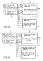
- a polarized voltage value calculator 15 for extracting voltage v pim normal to voltage v sm as shown in FIG. 16 and if this is for detecting a short-circuit, in case of, for example, AB phase, extract positive sequence voltage relative to the AB phase.
- A, B, and C indicate each phase of three-phase AC quantity of electricity.
- v psm (AB) -3 1/2 (v jm (C) - v jm (0)) + v sm (AB).
- v sm (0) indicates zero phase quantity of electricity.
- a fourth embodiment of the present invention will be described with reference to FIG. 17 . Description of the same configuration as the above-described embodiments is omitted while like reference numerals are attached thereto.
- FIG. 17 is a block diagram of a protection relay applied to description of this embodiment.
- outputs from the first filter 1 and the second filter 2 are inputted to a charging current compensation calculator 16 and its output is inputted to an operation decision section 18 which follows operation decision principle of ratio differential relay type so as to decide whether or not it is active.
- the charging current compensation calculator 16 corrects a setting value C s in the form of C s ⁇ C s ⁇ (k+2cos( ⁇ 0 T)/sin( ⁇ 0 T) and calculates i sm -C s ⁇ v jm using output current i sm from the first filter 1 and output voltage v jm from the second filter 2. In the meantime, C s ⁇ v jm indicates current compensation generated by charge capacity C s .
- opposing quantity of electricity (i sm -C s ⁇ v jm )B of an opposite terminal is received by transmission and reception section 17 and quantity of electricity of itself terminal is transmitted to the electric power station.
- B indicates quantity of electricity at an opposite terminal.
- the operation decision section 18 decides the operation based on vectorial sum of current which compensates for charge current at itself terminal obtained by the charging current compensation calculator 16 and current which compensates for charge current at a terminal of the opposite terminal, namely, scalar sum of amplitude value of differential current and currents which compensate for charge current at each terminal, according to expression (34) : ⁇ i sm - Cs ⁇ v jm + i sm - Cs ⁇ v jm ⁇ B ⁇ ⁇ ka ⁇ ⁇ i sm - Cs ⁇ v jm + i sm - Cs ⁇ v jm ⁇ B ⁇ + kb where, ⁇ am ⁇ represents quantity parallel to amplitude of AC quantity of electricity at time t m ; ka represents a proportion restricting coefficient; and kb represents minimum sensitivity current.
- noise error can be compressed by that amount.
- Such transfer function f(Z) is constructed with FIR fileter.
- the present invention is not restricted to this example, but the same integration error characteristic can be achieved even when it is constructed with recursive digital filter.
- a predetermined time differential equation can be solved approximately by passing through predetermined digital filters normal to each other in a wide frequency band, thereby achieving a high accuracy protection relay.
Landscapes
- Emergency Protection Circuit Devices (AREA)
- Testing Electric Properties And Detecting Electric Faults (AREA)
- Measurement Of Resistance Or Impedance (AREA)
- Locating Faults (AREA)
Claims (9)
- Schutzrelais zum Bestimmen, ob ein Fehlerpunkt eines Leistungssystems in einem vorbestimmten Bereich existiert, oder nicht, enthaltend
ein Filtermittel (1, 2) zum Eingeben von Abtastdaten einer Spannung und eines Stroms in dem Leistungssystem in ein digitales Filter, das eine vorbestimmte Übertragungsfunktion aufweist, und zum Ausgeben von ersten Spannungsdaten und ersten Stromdaten, und von zweiten Spannungsdaten und zweiten Stromdaten normal zu den ersten Spannungsdaten bzw. ersten Stromdaten;
ein Berechnungsmittel zum Berechnen eines vorbestimmten Messwerts basierend auf den ersten Spannungsdaten, den ersten Stromdaten, den zweiten Spannungsdaten und den zweiten Stromdaten zu einem ersten Zeitpunkt, und den ersten Spannungsdaten, ersten Stromdaten, zweiten Spannungsdaten und zweiten Stromdaten zu einem zweiten Zeitpunkt, der von dem ersten Zeitpunkt verschieden ist; und
ein Betriebsentscheidungsmittel zum Durchführen einer Betriebsentscheidung basierend auf dem vorbestimmten Messwert, der von dem Berechnungsmittel erhalten wird;
wobei das Filtermittel aufweist: ein erstes Filtermittel zum Eingeben der Abtastdaten in ein digitales Filter, das die erste Übertragungsfunktion f(Z)·(1+k·Z-1+Z-2) (Z gibt einen Z Umwandlungsoperator an) aufweist, um die ersten Spannungsdaten und Stromdaten auszugeben; und ein zweites Filtermittel zum Eingeben der Abtastdaten in ein digitales Filter, das die zweite Übertragungsfunktion f(Z)·(1-Z-2) (Z gibt einen Z Umwandlungsoperator an) aufweist, um die zweiten Spannungsdaten und die zweiten Stromdaten auszugeben. - Schutzrelais nach Anspruch 1, dadurch gekennzeichnet, dass der vorbestimmte Messwert, der durch das Berechnungsmittel erhalten wird, mindestens einen Reaktanzwert und/oder einen Ohm-Wert aufweist.
- Schutzrelais nach Anspruch 2, dadurch gekennzeichnet, dass das Filtermittel (1, 2) aufweist:ein erstes Filtermittel (1) zum Eingeben der Abtastdaten vm und im zu dem ersten Zeitpunkt Tm in ein digitales Filter, das eine Übertragungsfunktion f(Z)·(1+k·Z-1+Z-2) (Z gibt einen Z Umwandlungsoperator an) aufweist, um Spannungsdaten vsm und Stromdaten ism auszugeben; und ein zweites Filtermittel (2) zum Eingeben der Abtastdaten vm, im zu dem ersten Zeitpunkt Tm in ein digitales Filter, das die Übertragungsfunktion f(Z)·(1-Z-2) (Z gibt einen Z Umwandlungsoperator an) aufweist, um die Spannungsdaten vjm und Stromdaten ijm normal zu den Spannungsdaten vsm und Stromdaten ism auszugeben, wobeidas Berechnungsmittel einen Reaktanzwert Xm berechnet basierend auf:

indem die Erstspannungsdaten vsm, die ersten Stromdaten ism, die zweiten Spannungsdaten vjm und die zweiten Stromdaten ijm zu dem ersten Zeitpunkt tm und die ersten Spannungsdaten vsm-p, die ersten Stromdaten ism-p, die zweiten Spannungsdaten vjm-p und die zweiten Stromdaten ijm-p zu dem zweiten Zeitpunkt tm-p verwendet werden, unddas Betriebsentscheidungsmittel einen Betriebsentscheidungsabschnitt aufweist, der den Betrieb basierend auf dem Reaktanzwert Xm entscheidet. - Schutzrelais nach Anspruch 3, dadurch gekennzeichnet, dass das Betriebsentscheidungsmittel den Betrieb basierend auf einem Entscheidungsausdruck Xm≤Xs, der auf dem Reaktanzwert Xm und einem Setzwert Xs basiert, entscheidet.
- Schutzrelais nach Anspruch 3, dadurch gekennzeichnet, dass das Berechnungsmittel einen Ohm-Wert Rm berechnet basierend auf:Verwenden der ersten Spannungsdaten vsm, der ersten Stromdaten ism, der zweiten Spannungsdaten Vjm und der zweiten Stromdaten ijm zu dem ersten Zeitpunkt tm, und der ersten Spannungsdaten vsm-p, der ersten Stromdaten ism-p, der zweiten Spannungsdaten vjm-p und der zweiten Stromdaten ijm-p zu dem zweiten Zeitpunkt tm-p, wobei der Ohm-Wert Rm berechnet wird basierend auf
 das Betriebsentscheidungsmittel den Betrieb entscheidet von dem Reaktanzwert Xm von dem Berechnungsmittel gemäß einem Entscheidungsausdrucks:wobei;
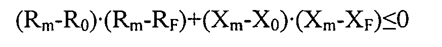 R0 (Ohm-Komponente) einen Offset mho zu einer Seite des Setzwerts darstellt;X0 (Reaktanz-Komponente) einen Offset mho zu der einen Seite des Setzwerts auch darstellt;RF (Ohm-Komponente) einen Offset mho zu einer anderen Seite des Setzwerts darstellt; undXF (eine Reaktanz-Komponente) einen Offset mho zu der anderen Seite des Setzwerts darstellt.
 - Schutzrelais nach Anspruch 2, dadurch gekennzeichnet, dass
das Filtermittel (1, 2) aufweist: ein erstes Filtermittel (1) zum Eingeben der Abtastdaten vm und im zu dem ersten Zeitpunkt Tm in ein digitales Filter, das eine Übertragungsfunktion f(Z)·(1+k·Z-1+Z-2) (Z gibt einen Z Umwandlungsoperator an) aufweist, um Spannungsdaten vsm und Stromdaten ism auszugeben; und ein zweites Filtermittel (2) zum Eingeben der Abtastdaten vm und im zu dem ersten Zeitpunkt Tm in ein digitales Filter, das eine Übertragung f(Z)-(1-Z-2) (Z gibt einen Z Umwandlungsoperator an) aufweist, um Spannungsdaten vjm und Stromdaten ijm normal zu den Spannungsdaten vsm und den Stromdaten ism auszugeben, und
das Berechnungsmittel einen Ohm-Wert Rm berechnet unter Verwendung der ersten und zweiten Spannungsdaten vsm, vjm, vsm-p und vjm-p und der ersten und zweiten Stromdaten ism, ijm, ism-p und ijm-p zu dem ersten und zweiten Zeitpunkt Tm und Tm-p, die durch das erste Filtermittel (1) und das zweite Filtermittel (2) erhalten werden, und
das Betriebsentscheidungsmittel den Betrieb basierend auf dem Ohm-Wert Rm von dem Berechnungsmittel entscheidet. - Schutzrelais nach Anspruch 1, ferner gekennzeichnet durch
ein polarisierter-Spannungswert-Berechnungsmittel zum Eingeben der ersten und zweiten Spannungsdaten und der ersten und zweiten Stromdaten, um eine dritte Spannung normal zu der ersten Spannung zu berechnen;
wobei das polarisierter-Spannungswert-Berechnungsmittel eine dritte Spannung vpjm basierend auf den ersten Spannungsdaten vsm, den ersten Stromdaten ism, den zweiten Spannungsdaten vjm und den zweiten Stromdaten ijm berechnet, und
das Betriebsentscheidungsmittel den Betrieb entscheidet basierend auf: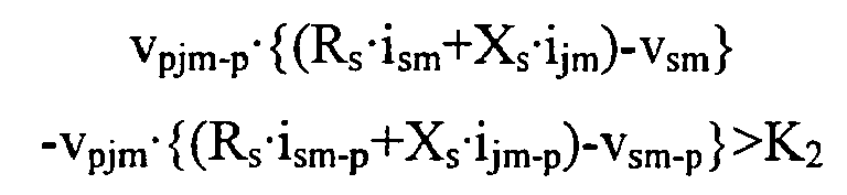
indem die dritte Spannung vpjm, die erste Spannung vsm, die ersten Stromdaten ism, die zweiten Spannungsdaten vjm, die zweiten Stromdaten ijm zu dem ersten Zeitpunkt tm und die ersten Spannungsdaten vjm-p, die ersten Stromdaten ijm-p zu dem zweiten Zeitpunkt tm-p und ein Setzwert (Rs, Xs) verwendet werden. - Schutzrelais nach Anspruch 7, dadurch gekennzeichnet, dass das polarisierter-Spannungswert-Berechnungsmittel eine Spannung vor vorbestimmten Zyklen einer Spannung normal zu den ersten Spannungen als die dritte Spannung berechnet.
- Schutzrelais nach Anspruch 1, dadurch gekennzeichnet, dass
das erste Filtermittel (1) Abtastdaten vm und im der Spannung v und des Stroms i in dem Leistungssystem in ein digitales Filter eingibt, um Spannungsdaten vsm und Stromdaten ism auszugeben, und
das zweite Filtermittel (2), in das die Spannungsdaten vm, im in ein digitales Filter eingegeben werden, Spannungsdaten vjm und Stromdaten ijm normal zu den Spannungsdaten vsm und Stromdaten ism ausgibt, ferner mit
einem Ladestromkompensationsberechnungsmittel (16) zum Berechnen einer Menge von Elektrizität, die in ism-C·vjm definiert ist durch die Stromdaten ism, die Spannungsdaten vjm und einen Setzwert Cs zum Zeitpunkt tm; und
ein Sende- und Empfangsmittel (17) zum Senden einer Ausgabe von dem Ladestromkompensationsberechnungsmittel an einen gegenüberliegenden Anschluss, und wenn die Elektrizitätsmenge an dem gegenüberliegenden Anschluss als B angenommen wird, empfangen eine Elektrizitätsmenge, die definiert ist durch (ism-C·vjm)B an den gegenüberliegenden Anschluss, und wobei
das Betriebsentscheidungsmittel (18) eine Betriebsentscheidung basierend auf den Ausgaben von dem Ladestromkompensationsberechnungsmittel und dem Sende/Empfangs-Mittel gemäß dem folgenden Ausdruck durchführt:
wobei,∥am∥ eine Größe parallel zur Amplitude einer AC Elektrizitätsgröße "a" zum Zeitpunkt tm darstellt;ka einen Proportionseinschränkungskoeffizienten darstellt; undkb einen Minimumempfindlichkeitsstrom darstellt.
Applications Claiming Priority (2)
| Application Number | Priority Date | Filing Date | Title |
|---|---|---|---|
| JP2001057948A JP2002262447A (ja) | 2001-03-02 | 2001-03-02 | 保護継電装置 |
| JP2001057948 | 2001-03-02 |
Publications (4)
| Publication Number | Publication Date |
|---|---|
| EP1237249A2 EP1237249A2 (de) | 2002-09-04 |
| EP1237249A3 EP1237249A3 (de) | 2004-02-04 |
| EP1237249B1 EP1237249B1 (de) | 2009-08-12 |
| EP1237249B9 true EP1237249B9 (de) | 2010-02-03 |
Family
ID=18917748
Family Applications (1)
| Application Number | Title | Priority Date | Filing Date |
|---|---|---|---|
| EP02004755A Expired - Lifetime EP1237249B9 (de) | 2001-03-02 | 2002-03-01 | Schutzrelais |
Country Status (6)
| Country | Link |
|---|---|
| US (1) | US6906903B2 (de) |
| EP (1) | EP1237249B9 (de) |
| JP (1) | JP2002262447A (de) |
| KR (1) | KR100465945B1 (de) |
| CN (1) | CN1374727B (de) |
| DE (1) | DE60233284D1 (de) |
Families Citing this family (9)
| Publication number | Priority date | Publication date | Assignee | Title |
|---|---|---|---|---|
| JP3857195B2 (ja) * | 2002-07-09 | 2006-12-13 | 株式会社東芝 | 距離継電装置 |
| US7319576B2 (en) * | 2005-08-18 | 2008-01-15 | Schweitzer Engineering Labortories, Inc. | Apparatus and method for providing differential protection for a phase angle regulating transformer in a power system |
| JP5401710B2 (ja) * | 2010-03-16 | 2014-01-29 | 株式会社東芝 | 保護継電装置および保護継電方法 |
| US8717725B2 (en) | 2010-12-02 | 2014-05-06 | Schweitzer Engineering Laboratories Inc | Dual-comparator restricted earth fault protection |
| CN103630726B (zh) * | 2013-10-30 | 2017-01-25 | 惠州市亿能电子有限公司 | 一种bms休眠模式下电池极化电压的估算方法 |
| EP2908397B1 (de) * | 2014-02-14 | 2017-08-09 | Nse Ag | Verfahren zum Schutz eines elektrischen Versorgungsnetzes |
| CN105572495B (zh) * | 2015-11-09 | 2019-08-23 | 上海凌翼动力科技有限公司 | 直流高压大电流电路开路故障动态模拟电子装置 |
| CN106324403B (zh) * | 2016-08-29 | 2019-03-19 | 国网江苏省电力公司电力科学研究院 | 一种基于状态识别的继电保护适应性滤波算法 |
| US10938198B2 (en) * | 2018-10-03 | 2021-03-02 | Schweitzer Engineering Laboratories, Inc. | Variable window length filter for protective relaying |
Family Cites Families (8)
| Publication number | Priority date | Publication date | Assignee | Title |
|---|---|---|---|---|
| SE384611B (sv) * | 1974-06-20 | 1976-05-10 | Asea Ab | Filtreringsanordning vid releskydd |
| US4093977A (en) * | 1976-06-15 | 1978-06-06 | Westinghouse Electric Corp. | Ground fault protective device |
| JPH0828934B2 (ja) * | 1984-07-31 | 1996-03-21 | 株式会社東芝 | 保護制御装置 |
| KR950004805B1 (ko) * | 1993-02-27 | 1995-05-10 | 현대중공업주식회사 | 전자식 배전반의 전동기 보호를 위한 디지탈 계전방법 |
| JP3322996B2 (ja) * | 1994-07-01 | 2002-09-09 | 東京電力株式会社 | 保護継電方式 |
| KR20000007462U (ko) * | 1998-09-30 | 2000-04-25 | 이해규 | 동작요소의 자동검출기능을 갖는 디지털보호계전기 |
| US6473723B1 (en) * | 1999-03-17 | 2002-10-29 | General Electric Company | Mimic high pass filter in a protective relay |
| CN2368206Y (zh) * | 1999-04-21 | 2000-03-08 | 国家电力公司南京电力自动化设备总厂 | 电力设备用微机继电保护装置 |
-
2001
- 2001-03-02 JP JP2001057948A patent/JP2002262447A/ja active Pending
-
2002
- 2002-03-01 EP EP02004755A patent/EP1237249B9/de not_active Expired - Lifetime
- 2002-03-01 DE DE60233284T patent/DE60233284D1/de not_active Expired - Lifetime
- 2002-03-01 CN CN021067163A patent/CN1374727B/zh not_active Expired - Fee Related
- 2002-03-01 US US10/085,708 patent/US6906903B2/en not_active Expired - Lifetime
- 2002-03-02 KR KR10-2002-0011210A patent/KR100465945B1/ko not_active Expired - Lifetime
Also Published As
| Publication number | Publication date |
|---|---|
| US20020149893A1 (en) | 2002-10-17 |
| US6906903B2 (en) | 2005-06-14 |
| KR100465945B1 (ko) | 2005-01-13 |
| CN1374727B (zh) | 2010-05-26 |
| CN1374727A (zh) | 2002-10-16 |
| KR20020070899A (ko) | 2002-09-11 |
| EP1237249A2 (de) | 2002-09-04 |
| JP2002262447A (ja) | 2002-09-13 |
| DE60233284D1 (de) | 2009-09-24 |
| EP1237249B1 (de) | 2009-08-12 |
| EP1237249A3 (de) | 2004-02-04 |
Similar Documents
| Publication | Publication Date | Title |
|---|---|---|
| US6456947B1 (en) | Digital current differential system | |
| US9461458B2 (en) | Method of distance protection of parallel transmission line | |
| US7106565B2 (en) | Directional ground relay system | |
| US4329727A (en) | Directional power distance relay | |
| US11757282B2 (en) | Method and device for controlling at least one circuit breaker of a power system | |
| EP1237249B9 (de) | Schutzrelais | |
| CA1198201A (en) | Protective relay apparatus | |
| JP2011015583A (ja) | 漏電検出方法、漏電検出装置及び漏電遮断器 | |
| EP2502318B1 (de) | Fuzzy-interferenzrelais und verfahren für stromdifferenzialschutz einer übertragungsleitung | |
| EP0718949B1 (de) | Schutzrelaissystem mit differenzfilter und summierfilter | |
| JP2011227020A (ja) | 配電用変圧器2次側地絡検出システム | |
| KR100699221B1 (ko) | 혼합 송전 선로 보호용 고장 판별 시스템 및 그 방법 | |
| US11962140B2 (en) | Coordination of protective elements in an electric power system | |
| JP4921246B2 (ja) | 地絡距離継電器 | |
| Johns et al. | A novel non-unit protection scheme based on fault generated high frequency noise on transmission lines | |
| Mao et al. | Protection of Teed transmission circuit using a new directional comparison technique | |
| US20250279255A1 (en) | Protection through a power transformer using compensated voltages and currents | |
| Gajić et al. | Earth-fault protection challenges for modern distribution power systems | |
| CN120414444A (zh) | 一种基于电压补偿的中性点绝缘的配电网零序电流保护方法 | |
| AU6542200A (en) | Digital current differential system | |
| Lai et al. | A new approach to protecting transmission systems with fault generated noise | |
| JPS6124899B2 (de) | ||
| JPS5986418A (ja) | 静止形保護継電器 |
Legal Events
| Date | Code | Title | Description |
|---|---|---|---|
| PUAI | Public reference made under article 153(3) epc to a published international application that has entered the european phase |
Free format text: ORIGINAL CODE: 0009012 |
|
| 17P | Request for examination filed |
Effective date: 20020301 |
|
| AK | Designated contracting states |
Kind code of ref document: A2 Designated state(s): AT BE CH CY DE DK ES FI FR GB GR IE IT LI LU MC NL PT SE TR |
|
| AX | Request for extension of the european patent |
Free format text: AL;LT;LV;MK;RO;SI |
|
| PUAL | Search report despatched |
Free format text: ORIGINAL CODE: 0009013 |
|
| AK | Designated contracting states |
Kind code of ref document: A3 Designated state(s): AT BE CH CY DE DK ES FI FR GB GR IE IT LI LU MC NL PT SE TR |
|
| AX | Request for extension of the european patent |
Extension state: AL LT LV MK RO SI |
|
| AKX | Designation fees paid |
Designated state(s): DE SE |
|
| 17Q | First examination report despatched |
Effective date: 20070208 |
|
| GRAP | Despatch of communication of intention to grant a patent |
Free format text: ORIGINAL CODE: EPIDOSNIGR1 |
|
| GRAS | Grant fee paid |
Free format text: ORIGINAL CODE: EPIDOSNIGR3 |
|
| GRAA | (expected) grant |
Free format text: ORIGINAL CODE: 0009210 |
|
| AK | Designated contracting states |
Kind code of ref document: B1 Designated state(s): DE SE |
|
| REF | Corresponds to: |
Ref document number: 60233284 Country of ref document: DE Date of ref document: 20090924 Kind code of ref document: P |
|
| REG | Reference to a national code |
Ref country code: SE Ref legal event code: TRGR |
|
| PLBE | No opposition filed within time limit |
Free format text: ORIGINAL CODE: 0009261 |
|
| STAA | Information on the status of an ep patent application or granted ep patent |
Free format text: STATUS: NO OPPOSITION FILED WITHIN TIME LIMIT |
|
| 26N | No opposition filed |
Effective date: 20100517 |
|
| PGFP | Annual fee paid to national office [announced via postgrant information from national office to epo] |
Ref country code: DE Payment date: 20180214 Year of fee payment: 17 |
|
| PGFP | Annual fee paid to national office [announced via postgrant information from national office to epo] |
Ref country code: SE Payment date: 20180313 Year of fee payment: 17 |
|
| REG | Reference to a national code |
Ref country code: DE Ref legal event code: R119 Ref document number: 60233284 Country of ref document: DE |
|
| REG | Reference to a national code |
Ref country code: SE Ref legal event code: EUG |
|
| PG25 | Lapsed in a contracting state [announced via postgrant information from national office to epo] |
Ref country code: SE Free format text: LAPSE BECAUSE OF NON-PAYMENT OF DUE FEES Effective date: 20190302 |
|
| PG25 | Lapsed in a contracting state [announced via postgrant information from national office to epo] |
Ref country code: DE Free format text: LAPSE BECAUSE OF NON-PAYMENT OF DUE FEES Effective date: 20191001 |