EP1237249B1 - Protection relay - Google Patents
Protection relay Download PDFInfo
- Publication number
- EP1237249B1 EP1237249B1 EP02004755A EP02004755A EP1237249B1 EP 1237249 B1 EP1237249 B1 EP 1237249B1 EP 02004755 A EP02004755 A EP 02004755A EP 02004755 A EP02004755 A EP 02004755A EP 1237249 B1 EP1237249 B1 EP 1237249B1
- Authority
- EP
- European Patent Office
- Prior art keywords
- data
- voltage
- current
- current data
- value
- Prior art date
- Legal status (The legal status is an assumption and is not a legal conclusion. Google has not performed a legal analysis and makes no representation as to the accuracy of the status listed.)
- Expired - Lifetime
Links
- 230000014509 gene expression Effects 0.000 claims description 67
- 238000012546 transfer Methods 0.000 claims description 30
- 238000005070 sampling Methods 0.000 claims description 27
- 238000004364 calculation method Methods 0.000 claims description 20
- 230000005540 biological transmission Effects 0.000 claims description 13
- 230000005611 electricity Effects 0.000 claims description 12
- 238000006243 chemical reaction Methods 0.000 claims description 10
- 238000005259 measurement Methods 0.000 claims description 6
- 230000035945 sensitivity Effects 0.000 claims description 5
- 238000010586 diagram Methods 0.000 description 20
- 238000000034 method Methods 0.000 description 9
- 230000003321 amplification Effects 0.000 description 8
- 238000003199 nucleic acid amplification method Methods 0.000 description 8
- 238000012986 modification Methods 0.000 description 5
- 230000004048 modification Effects 0.000 description 5
- 239000000284 extract Substances 0.000 description 3
- 230000010354 integration Effects 0.000 description 3
- 238000013016 damping Methods 0.000 description 2
- 230000003111 delayed effect Effects 0.000 description 2
- 238000009434 installation Methods 0.000 description 2
- 101100042630 Caenorhabditis elegans sin-3 gene Proteins 0.000 description 1
- 239000003990 capacitor Substances 0.000 description 1
- 238000007796 conventional method Methods 0.000 description 1
- 230000007423 decrease Effects 0.000 description 1
- 230000003247 decreasing effect Effects 0.000 description 1
- 238000001514 detection method Methods 0.000 description 1
- 230000000694 effects Effects 0.000 description 1
- 230000001939 inductive effect Effects 0.000 description 1
- 230000002035 prolonged effect Effects 0.000 description 1
- 230000001681 protective effect Effects 0.000 description 1
- 238000013139 quantization Methods 0.000 description 1
Images

Classifications
-
- H—ELECTRICITY
- H02—GENERATION; CONVERSION OR DISTRIBUTION OF ELECTRIC POWER
- H02H—EMERGENCY PROTECTIVE CIRCUIT ARRANGEMENTS
- H02H3/00—Emergency protective circuit arrangements for automatic disconnection directly responsive to an undesired change from normal electric working condition with or without subsequent reconnection ; integrated protection
- H02H3/02—Details
-
- H—ELECTRICITY
- H02—GENERATION; CONVERSION OR DISTRIBUTION OF ELECTRIC POWER
- H02H—EMERGENCY PROTECTIVE CIRCUIT ARRANGEMENTS
- H02H3/00—Emergency protective circuit arrangements for automatic disconnection directly responsive to an undesired change from normal electric working condition with or without subsequent reconnection ; integrated protection
- H02H3/40—Emergency protective circuit arrangements for automatic disconnection directly responsive to an undesired change from normal electric working condition with or without subsequent reconnection ; integrated protection responsive to ratio of voltage and current
-
- H—ELECTRICITY
- H02—GENERATION; CONVERSION OR DISTRIBUTION OF ELECTRIC POWER
- H02H—EMERGENCY PROTECTIVE CIRCUIT ARRANGEMENTS
- H02H1/00—Details of emergency protective circuit arrangements
- H02H1/0092—Details of emergency protective circuit arrangements concerning the data processing means, e.g. expert systems, neural networks
Definitions
- the present invention relates to a protection relay in which an influence of distortion component of fault current generated by a fault in a power system is suppressed.
- a protection relay is used to monitor a power system.
- a main technical subject of such a protection relay is to reduce an influence of harmonics in fault current and fault voltage generated in a fault in a system contained in a signal inputted from the system.
- filter delay time needs to be prolonged, so that relay operation time is delayed.
- L m /L (true value) is as expressed in the expression (4) under conditions of the expressions (5) and (6), so that frequency characteristic of X m /X (true value) is as indicated with the dotted curve of FIG. 2 .
- L m / L true value tan ⁇ 0 ⁇ T / 2 / tan ⁇ ⁇ T / 2
- i m Isin ⁇ ⁇ t m
- frequency characteristic of X m /X (true value) is as indicated with the dotted curve of FIG. 2 .
- FIG. 2 indicates that the value of ( ⁇ T/2) only should be suppressed to substantially 1 (that is, the sampling period should be set small) when this value (L m /L) is near twice or three times the fundamental wave.
- the value of the expression (7) is a very small value with respect to an amplitude value I. Therefore, a relative value of noise (quantization error generated at the time of A/D conversion, white noise generated in an analog circuit) contained in sampling data (i m , i m-1 ) is increased thereby disabling practical use of this method.
- EP 0 718 949 discloses a protection relay for determining whether or not a fault point of a power system exists in a predetermined range by using a trapezoidal integration approximation algorithm which can improve the accuracy by the fast sampling to the protective relay.
- An object of the present invention is to provide an improved protection relay.
- a protection relay for determining whether or not a faultal point of a power system exists in a predetermined range according to a first aspect of the present invention which is disclosed in claim 1.
- a protection relay for determining whether or not a faultal point of a power system exists in a predetermined range according to a second aspect of the present invention which is disclosed in claim 7.
- a protection relay for determining whether or not a faultal point of power system exists in a predetermined range according to a third aspect of the present invention which is disclosed in claim 9.
- Voltage can be obtained in the same manner as current and if it is assumed that the voltages are v sm and v jm , they are in such a relation that they are normal to each other.
- i jm , i sm , and v sm at time t m and i jm-1 , i sm-1 , and v sm-1 at time t m-1 are substituted for:
- Xm - v sm ⁇ i sm - p + i sm ⁇ v sm - p - i jm ⁇ i sm - p + i jm - p ⁇ i sm
- voltage v sm is provided in the form of:
- v sm V ⁇ k + 2 ⁇ cos ⁇ ⁇ T ⁇ ( sin n + 1 ⁇ ⁇ ⁇ T / 2 / sin ⁇ ⁇ T / 2 ⁇ sin ⁇ ⁇ t m + ⁇ - n + 2 ⁇ ⁇ ⁇ T / 2
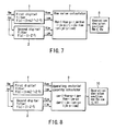
- FIG. 4 is a block diagram showing schematically the structure of the protection relay according to the first embodiment.
- the protection relay of the first embodiment suppresses amplification of the noise error contained in minute quantity of data even when the sampling period is shortened, in order to secure performance of frequency characteristic indicated in the expression (4).
- a first (digital) filter 1 comprises a digital filter (Z indicates a Z conversion operator) which outputs sampling data v m and i m about voltage v and current i of a power system as voltage data v sm and current data i sm through transfer function f(Z) ⁇ (1+k ⁇ Z -1 +Z -2 ) and extracts predetermined frequency components of voltage and current of a power system (not shown), which is a protecting object.
- Z indicates a Z conversion operator
- a second (digital) filter 2 comprises a digital filter (Z indicates a Z conversion operator) which outputs sampling data v m and i m as voltage data v jm and i jm through transfer function f(Z) ⁇ (1-Z -2 ) and extracts voltage and current normal to the first filter 1 in all frequency components.
- Z indicates a Z conversion operator
- a reactance value calculator 3 calculates a reactance value X m from voltage data v sm , current data i sm , voltage data v jm and voltage data i jm at time t m and voltage data i sm-p , current data i sm-p , voltage data v jm-p and current data i jm-p at time t m-p .
- An operation decision section 4 compares the reactance value X m obtained by the reactance calculator 3 with a preliminarily set integer (whether or not X m ⁇ X s is determined with X s ).
- the preliminarily set integer value is called setting value in this specification.
- the first filter having the transfer function f(Z) ⁇ (1+k ⁇ Z -1 +Z -2 ) receives input of sampling data v m and i m about voltage v and current i of the power system and outputs voltage data v sm and current data i sm .
- the second filter having the transfer function f(Z) ⁇ (1-Z -2 ) receives input of sampling data v m and i m about the voltage v and current i and outputs voltage data v jm and current data i jm .
- the reactance value calculator 3 calculates a reactance value X m from the voltage data v sm and current data i sm obtained by the first filter 1 and voltage data v jm and current data i jm obtained by the second filter 2 at time t m , and voltage data v sm-p and current data i sm-p obtained by the first filter 1 and voltage data v jm-p and current data i jm-p obtained by the second filter 2 at time t m-p according to the expression (17):
- Xm - v sm ⁇ i sm - p + i sm ⁇ v sm - p - i jm ⁇ i sm - p + i jm - p ⁇ i sm
- m and p represent sampling time series.
- the operation decision section 4 decides whether or not X m ⁇ X s is established from the reactance value X m and setting value X s obtained by the reactance value calculator 3 and when that relation is established, it decides it is active and otherwise, it decides it is inactive.
- the transfer functions of the first and second filters 1 and 2 are expressed in f(Z) ⁇ (1+k ⁇ Z -1 +Z -2 ) and f(Z) ⁇ (1-Z -2 ) when the Z conversion operator is employed.
- the outputs of the first and second filters 1 and 2 are normal to each other. There is a relation that the output of the first filter 1 is delayed at 90° with respect to the output of the second filter 2.
- transfer function 1 f(Z)
- transfer function 2 (1+k ⁇ Z -1 +Z -2 )
- transfer function 3 1-Z -2 and form the first filter 1 and the second filter 2 by combining those.
- the same output can be obtained by passing the input voltage and current through a digital filter of the transfer function 1 and then passing its output through digital filters of the transfer functions 2 and 3.
- the operation decision section 4 corrects the decision expression using the reactance value X m , setting value X s and preliminarily set fundamental wave constant sin ( ⁇ 0 T)/(k+2 ⁇ cos( ⁇ 0 T)) with respect to the reactance value X m calculated by the reactance value calculator 3 as indicated in the expression (18) so as to decide whether or not it is active.
- Such operation decision is carried out plural times ordinarily.
- the reactance value calculator 3 calculates the reactance value using outputs of the first filter 1 and the second filter 2 and the operation decision section 4 decides whether or not it is active according to the condition expression (18) based on that reactance value.
- an operating restarint quantity calculator 5 to calculate a m and b m according to the expression (19) based on the outputs of the first filter 1 and the second filter 2 and then for an operation decision section 6 to decide the operation according to the expression (20) to be described later using that result.
- a m - v m ⁇ i sm - p + v sm - p ⁇ i m
- b m - i jm ⁇ i sm - p + i jm - p ⁇ i sm
- the operation decision section 6 corrects sensitivity constant K 0 and reactance setting value X s to X s ⁇ X s /(sin( ⁇ 0 T)/(k+2 ⁇ cos( ⁇ 0 T)) using a m and b m outputted in this way and decides the operation according to a decision expression of the expression (21).
- Ohm value calculator 7 defined by expression (22) as shown in FIG. 7 as such calculation means or an operation decision section 8 defined by the expression (25), which will be described later.
- Xm - v sm ⁇ i sm - p + i sm ⁇ v sm - p - i jm ⁇ i sm - p + i jm - p ⁇ i sm
- the operation decision section 8 decides whether or not a decision expression for the expression (25) is established based on the Ohm value R m and the setting value R s calculated from the expression (24) and when that expression is established, it decides it is active.
- the operation decision section 10 decides whether or not it is active based on the decision expression (28) from c m , b m , Ohm setting value R s and sensitivity constant K l .
- Such protection relay has Ohm characteristic shown in FIG. 9 like the configuration described with reference to FIG. 7 before and is different from it only in its realization method.
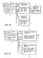
- FIG. 4 indicates calculation of reactance and FIGS. 5 , 8 indicate calculation of operating restarint quantity, and FIG. 7 indicates calculation of Ohm value and decision of operation based thereon.
- This embodiment contains the Ohm value calculator 7 and reactance value calculator 3 as shown in FIG. 10 and then, the operation decision section 11 decides the operation using these outputs.
- the reactance value calculator 3 calculates reactance X m according to the expression (13).
- the operation decision section 11 decides whether or not it is active according to the expression (29) using the Ohm value R m and the reactance value X m .
- R 0 (Ohm component) represents an offset mho near side setting value
- X 0 (reactance component) represents an offset mho near side setting value
- R F Ohm component
- X F reactance component
- a protection relay of this embodiment comprises a polarized voltage value calculator 12 in which voltage v sm , current i sm and voltage v jm , current i jm are inputted in order to extract voltage v pim normal to voltage v sm and an operation decision section 13 in which the aforementioned voltages and currents are inputted while voltage v pim is inputted from the polarized voltage value calculator 12 so as to decide whether or not it is active according to the expression (30).
- R s and X s are setting value s of an Ohm component and a reactance component respectively, while X s is corrected in the form of X s ⁇ X s / (sin( ⁇ 0T)/(k+2 ⁇ cos( ⁇ 0T)).
- expression (32) indicates operation principle expression of mho characteristic shown in FIG. 14 if its frequency is basic frequency.
- the above-described structure indicates a case where voltage v pjm normal to voltage v sm in the fundamental wave is extracted by the polarized voltage value calculator 12.
- the present invention is not restricted to this example.
- the voltage v pjm and voltage v sm are indicated in the expression (33).
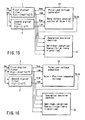
- a polarized voltage value calculator 15 for extracting voltage v pim normal to voltage v sm as shown in FIG. 16 and if this is for detecting a short-circuit, in case of, for example, AB phase, extract positive sequence voltage relative to the AB phase.
- A, B, and C indicate each phase of three-phase AC quantity of electricity.
- v psm (AB) -3 1/2 (v jm (C) - v jm (0)) + v sm (AB).
- v sm (0) indicates zero phase quantity of electricity.
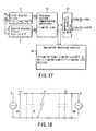
- a fourth embodiment of the present invention will be described with reference to FIG. 17 . Description of the same configuration as the above-described embodiments is omitted while like reference numerals are attached thereto.
- FIG. 17 is a block diagram of a protection relay applied to description of this embodiment.
- outputs from the first filter 1 and the second filter 2 are inputted to a charging current compensation calculator 16 and its output is inputted to an operation decision section 18 which follows operation decision principle of ratio differential relay type so as to decide whether or not it is active.
- the charging current compensation calculator 16 corrects a setting value C s in the form of C s ⁇ C s ⁇ (k+2cos( ⁇ 0 T)/sin( ⁇ 0 T) and calculates i sm -C s ⁇ v jm using output current i sm from the first filter 1 and output voltage v jm from the second filter 2. In the meantime, C s ⁇ v jm indicates current compensation generated by charge capacity C s .
- opposing quantity of electricity (i sm -C s ⁇ v jm )B of an opposite terminal is received by transmission and reception section 17 and quantity of electricity of itself terminal is transmitted to the electric power station.
- B indicates quantity of electricity at an opposite terminal.
- the operation decision section 18 decides the operation based on vectorial sum of current which compensates for charge current at itself terminal obtained by the charging current compensation calculator 16 and current which compensates for charge current at a terminal of the opposite terminal, namely, scalar sum of amplitude value of differential current and currents which compensate for charge current at each terminal, according to expression (34) : ⁇ i sm - Cs ⁇ v jm + i sm - Cs ⁇ v jm ⁇ B ⁇ ⁇ ka ⁇ ⁇ i sm - Cs ⁇ v jm + i sm - Cs ⁇ v jm ⁇ B ⁇ + kb where, ⁇ am ⁇ represents quantity parallel to amplitude of AC quantity of electricity at time t m ; ka represents a proportion restricting coefficient; and kb represents minimum sensitivity current.
- noise error can be compressed by that amount.
- Such transfer function f(Z) is constructed with FIR fileter.
- the present invention is not restricted to this example, but the same integration error characteristic can be achieved even when it is constructed with recursive digital filter.
- a predetermined time differential equation can be solved approximately by passing through predetermined digital filters normal to each other in a wide frequency band, thereby achieving a high accuracy protection relay.
Landscapes
- Emergency Protection Circuit Devices (AREA)
- Testing Electric Properties And Detecting Electric Faults (AREA)
- Measurement Of Resistance Or Impedance (AREA)
- Locating Faults (AREA)
Description
- The present invention relates to a protection relay in which an influence of distortion component of fault current generated by a fault in a power system is suppressed.
- Generally, a protection relay is used to monitor a power system. A main technical subject of such a protection relay is to reduce an influence of harmonics in fault current and fault voltage generated in a fault in a system contained in a signal inputted from the system.
- Particularly because charging capacity of a system is increased in underground power transmission cable, phase modifying capacitor and the like, the order of generated harmonics tends to be lowered.
- Thus, if it is intended to secure a desired damping amount according to a conventional method for damping the harmonic component with a digital filter, filter delay time needs to be prolonged, so that relay operation time is delayed.
- For the reason, an approximation method, which is not affected by harmonic theoretically even if such harmonics is contained has been employed in recent years.
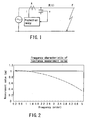
- An example of such approximation method will be described with reference to
FIG. 1 . Power transmission impedance constant up to a fault point F will be considered with reference toFIG. 1 . Voltage and current of a protection relay installation point A are assumed to be v and i when resistance is R and inductance is L. If it is assumed that the voltage at the faultal point F is zero, differential equation of apower transmission line 2 can be expressed in an expression (1).
- By calculating a differential item (di/dt) of the expression (1) approximately, detection accuracy can be improved even if harmonic is not removed with a filter. An example of a concrete method for digital calculation actually adapted is shown below.

- When a reactance value X (= ω0 · L) is calculated from the expression (2), the inductance is expressed in expression (3).

- Lm/L (true value) is as expressed in the expression (4) under conditions of the expressions (5) and (6), so that frequency characteristic of Xm/X (true value) is as indicated with the dotted curve of
FIG. 2 .
- Where,


- Therefore, frequency characteristic of Xm/X (true value) is as indicated with the dotted curve of
FIG. 2 . - In
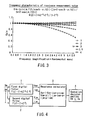
FIG. 2 , its abscissa axis indicates frequency (order) and its ordinate axis indicates a reactance measurement value when basic frequency of system electrical quantity is 50 Hz. Further, inFIG. 2 , its dotted curve indicates a case of sampling at 600 Hz and its solid line indicates a case of sampling at 4800 Hz. - As indicated in
FIG. 2 , the value of Lm/L (true value) decreases below 1 as the frequency departs from its fundamental wave.FIG. 2 indicates that the value of (ωT/2) only should be suppressed to substantially 1 (that is, the sampling period should be set small) when this value (Lm/L) is near twice or three times the fundamental wave. - Frequency characteristic when the sampling frequency is actually multiplied eight times is indicated by the solid line of
FIG. 2 . Quantitavely, the relation between an approximate amount (im - im-1) of the differential item and a differentiated amount (vm+vm-1) is indicated by the expressions (7) and (8). Therefore, if the sampling frequency is raised (the period is decreased), approximation accuracy of the differential item can be raised.

- However, the value of the expression (7) is a very small value with respect to an amplitude value I. Therefore, a relative value of noise (quantization error generated at the time of A/D conversion, white noise generated in an analog circuit) contained in sampling data (im, im-1) is increased thereby disabling practical use of this method.
- For example, when the sampling period T is T = 1/4800 sec, ω0 = 2π·50 Hz, the second item ε/ (ω0T/2) on the right side of the expression (9) is amplified to about 30 times. An ε in the expression (9) is noise error.

-
EP 0 718 949 - An object of the present invention is to provide an improved protection relay.
- A protection relay for determining whether or not a faultal point of a power system exists in a predetermined range, according to a first aspect of the present invention which is disclosed in
claim 1. - A protection relay for determining whether or not a faultal point of a power system exists in a predetermined range, according to a second aspect of the present invention which is disclosed in
claim 7. - A protection relay for determining whether or not a faultal point of power system exists in a predetermined range, according to a third aspect of the present invention which is disclosed in
claim 9. - This summary of the invention does not necessarily describe all necessary features so that the invention may also be a sub-combination of these described features.
- The invention can be more fully understood from the following detailed description when taken in conjunction with the accompanying drawings, in which:
-
FIG. 1 is a power system diagram, which is an object of the present invention; -
FIG. 2 is a diagram showing frequency characteristic of a reactance measurement value which is an object of the present invention; -
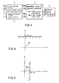
FIG. 3 is a diagram showing frequency characteristic of a reactance measurement value in a digital filter structure, which is an object of the present invention; -
FIG. 4 is a block diagram of a protection relay according to a first embodiment of the present invention; -
FIG. 5 is a block diagram of a protection relay according to a first modification of the first embodiment; -
FIG. 6 is a diagram showing reactance characteristic on an impedance plane; -
FIG. 7 is a block diagram of a protection relay according to a second modification of the first embodiment; -
FIG. 8 is a block diagram of a protection relay according to a third modification of the first embodiment; -
FIG. 9 is a diagram showing Ohm characteristic on an impedance plane: -
FIG. 10 is a block diagram of a protection relay according to a second embodiment of the present invention; -
FIG. 11 is a diagram showing offset mho characteristic on an impedance plane; -
FIG. 12 is a block diagram of a protection relay according to a third embodiment of the present invention; -
FIG. 13 is a diagram showing the relation between maximum sensitive angle of mho characteristic and permanent impedance; -
FIG. 14 is a diagram showing mho characteristic expressed with reference to current; -
FIG. 15 is a block diagram of a protection relay according to a first modification of the third embodiment; -
FIG. 16 is a block diagram of a protection relay according to a second modification of the third embodiment; -
FIG. 17 is a block diagram of a protection relay according to a fourth embodiment of the present invention; and -
FIG. 18 is a diagram for explaining a telegraph equation of a power transmission line. - Prior to description of respective embodiments of the present invention, the principle of the present invention will be described. If sampling data of current i = I · sin(ωt) is passed through transfer function f(Z) = (1+Z-1+Z-2+ ··· +Z-n), current i'sm at time tm indicated in the expression (10) is obtained.

- If this current i'sm is passed through transfer function (1+k·Z-1+Z-2), current ism at time tm indicated in the expression (11) is obtained.

- Likewise, current i = I · sin (ωt) is passed through the transfer function f(Z) · (1-Z-2), current ijm at time tm is obtained as indicated in the expression (12).
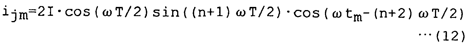
- Voltage can be obtained in the same manner as current and if it is assumed that the voltages are vsm and vjm, they are in such a relation that they are normal to each other.
- Thus, if as the fundamental wave, its value which is as near 1 as possible is selected as long as the quantity for determining the size of the right side of the expression (12) is not |sin((n+1)ωT/2)| << 1, performance of frequency characteristic can be assured while suppressing amplification of noise error.
- Therefore, if ijm, ism, and vsm at time tm and ijm-1, ism-1, and vsm-1 at time tm-1 are substituted for:


- As a result, a reactance value Xm is indicated in the expression (15):

- Therefore, when n is increased sufficiently in the expression (12), an influence of the noise error can be reduced. Frequency characteristic of Xm relative to the fundamental wave can be indicated in a graph shown in
FIG. 3 . From this graph, it is evident that k = 4 provides the most excellent frequency characteristic.
- A protection relay according to a first embodiment of the present invention will be described based on the above-described principle with reference to
FIG. 4. FIG. 4 is a block diagram showing schematically the structure of the protection relay according to the first embodiment. The protection relay of the first embodiment suppresses amplification of the noise error contained in minute quantity of data even when the sampling period is shortened, in order to secure performance of frequency characteristic indicated in the expression (4). - Referring to
FIG. 4 , a first (digital)filter 1 comprises a digital filter (Z indicates a Z conversion operator) which outputs sampling data vm and im about voltage v and current i of a power system as voltage data vsm and current data ism through transfer function f(Z) · (1+k·Z-1+Z-2) and extracts predetermined frequency components of voltage and current of a power system (not shown), which is a protecting object. - A second (digital)
filter 2 comprises a digital filter (Z indicates a Z conversion operator) which outputs sampling data vm and im as voltage data vjm and ijm through transfer function f(Z) · (1-Z-2) and extracts voltage and current normal to thefirst filter 1 in all frequency components. - A
reactance value calculator 3 calculates a reactance value Xm from voltage data vsm, current data ism, voltage data vjm and voltage data ijm at time tm and voltage data ism-p, current data ism-p, voltage data vjm-p and current data ijm-p at time tm-p. - An operation decision section 4 compares the reactance value Xm obtained by the
reactance calculator 3 with a preliminarily set integer (whether or not Xm ≤ Xs is determined with Xs). The preliminarily set integer value is called setting value in this specification. - With such a configuration, the first filter having the transfer function f(Z)·(1+k·Z-1+Z-2) receives input of sampling data vm and im about voltage v and current i of the power system and outputs voltage data vsm and current data ism.
- Further, the second filter having the transfer function f(Z) · (1-Z-2) receives input of sampling data vm and im about the voltage v and current i and outputs voltage data vjm and current data ijm.
- The
reactance value calculator 3 calculates a reactance value Xm from the voltage data vsm and current data ism obtained by thefirst filter 1 and voltage data vjm and current data ijm obtained by thesecond filter 2 at time tm, and voltage data vsm-p and current data ism-p obtained by thefirst filter 1 and voltage data vjm-p and current data ijm-p obtained by thesecond filter 2 at time tm-p according to the expression (17):
- Further, the operation decision section 4 decides whether or not Xm ≤ Xs is established from the reactance value Xm and setting value Xs obtained by the
reactance value calculator 3 and when that relation is established, it decides it is active and otherwise, it decides it is inactive. - The transfer functions of the first and
second filters second filters first filter 1 is delayed at 90° with respect to the output of thesecond filter 2. - It is permissible to define these transfer functions with transfer function 1: f(Z), transfer function 2: (1+k·Z-1+Z-2) and transfer function 3: 1-Z-2 and form the
first filter 1 and thesecond filter 2 by combining those. - That is, the same output can be obtained by passing the input voltage and current through a digital filter of the
transfer function 1 and then passing its output through digital filters of thetransfer functions - The
reactance value calculator 3 ofFIG. 4 calculates a reactance value from a protection relay installation point in a power transmission line ofFIG. 1 up to a faultal point according to the expression (17). Assuming that the input voltage and current are i = I · sin(ωt), and v = V · sin(ωt+θ), the expression (17) can be expressed in the expression (15). - The operation decision section 4 corrects the decision expression using the reactance value Xm, setting value Xs and preliminarily set fundamental wave constant sin (ω0T)/(k+2·cos(ω0T)) with respect to the reactance value Xm calculated by the
reactance value calculator 3 as indicated in the expression (18) so as to decide whether or not it is active. Such operation decision is carried out plural times ordinarily.
- Consequently, amplification of error due to approximation of the differential item is suppressed, so that Lm/L (true value) becomes a characteristic which is as near 1 as possible in a wide frequency band. Therefore, it is possible to block an influence even when a harmonic component occurs in fault voltage and fault current of the power system thereby improving reliability.
- According to the above description, the
reactance value calculator 3 calculates the reactance value using outputs of thefirst filter 1 and thesecond filter 2 and the operation decision section 4 decides whether or not it is active according to the condition expression (18) based on that reactance value. - The present invention is not restricted to this example, but it is permissible for an operating
restarint quantity calculator 5 to calculate am and bm according to the expression (19) based on the outputs of thefirst filter 1 and thesecond filter 2 and then for anoperation decision section 6 to decide the operation according to the expression (20) to be described later using that result.
- That is, when current i = I · sin(ωt) and voltage v = V·sin(ωt+θ) are inputted to the
first filter 1 of the transfer function f(Z) · (1-k · Z-1+Z-2) and thesecond filter 2 of the transfer function f(Z) · (1-Z-2), the expression (19) is converted to the expression (20), providing that f(Z) = (1+Z-1+Z-2+ ··· +Z-n) .
- The
operation decision section 6 corrects sensitivity constant K0 and reactance setting value Xs to Xs ← Xs/(sin(ω0T)/(k+2·cos(ω0T)) using am and bm outputted in this way and decides the operation according to a decision expression of the expression (21).
- Although this is a different method from the above-described method, it has the reactance characteristic as shown in
FIG. 6 like that example. - Consequently, amplification of error due to approximation of the differential item is suppressed, so that Lm/L (true value) becomes a characteristic which is as near 1 as possible in a wide frequency band. Therefore, it is possible to block an influence even when a harmonic component occurs in fault voltage and fault current of the power system thereby improving reliability.
- Further, it is permissible to use an
Ohm value calculator 7 defined by expression (22) as shown inFIG. 7 as such calculation means or anoperation decision section 8 defined by the expression (25), which will be described later.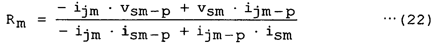
- With this configuration, when current i = I·sin(ωt) and voltage v = V·sin(ωt+θ) are inputted into the
first filter 1 of the transfer function f(Z) · (1+k · Z-1+Z-2) and thesecond filter 2 of the transfer function f(Z) . (1-Z-2), the expression (23) is established, providing that f(Z) = (1+Z-1+Z-2+ ··· +Z-n). Further, the Ohm value Rm is converted to the expression (24) because of the relation of the expression (20).

- The
operation decision section 8 decides whether or not a decision expression for the expression (25) is established based on the Ohm value Rm and the setting value Rs calculated from the expression (24) and when that expression is established, it decides it is active.
- Consequently, amplification of error due to approximation of the differential item is suppressed, so that Lm/L (true value) becomes a characteristic which is as near 1 as possible in a wide frequency band. Therefore, it is possible to block an influence even when a harmonic component occurs in fault voltage and fault current of the power system thereby improving reliability.
- Further, it is permissible to use an operation restricting
quantity calculator 9 defined by the expression (26) shown inFIG. 8 or anoperation decision section 10 defined by the expression (28) which will be described later, as such calculation means.
- That is, when current i = I·sin(ωt) and voltage v = V·sin(ωt+θ) are inputted to the
first filter 1 of the transfer function f(Z) · (1-k·Z-1+Z-2) and thesecond filter 2 of the transfer function f(Z) · (1-Z-2), the expression (26) is converted to the expression (27), providing that f(Z) = (1+Z-1+Z-2+ ... +Z-n).
- Then, the
operation decision section 10 decides whether or not it is active based on the decision expression (28) from cm, bm, Ohm setting value Rs and sensitivity constant Kl.
- Such protection relay has Ohm characteristic shown in
FIG. 9 like the configuration described with reference toFIG. 7 before and is different from it only in its realization method. - Consequently, amplification of error due to approximation of the differential item is suppressed, so that Lm/L (true value) becomes a characteristic which is as near 1 as possible in a wide frequency band. Therefore, it is possible to block an influence even when a harmonic component occurs in fault voltage and fault current of the power system thereby improving reliability.
- Next, a second embodiment of the present invention will be described with reference to the accompanying drawings. A description of the same configuration as the above-described embodiment is omitted appropriately while like reference numerals are attached to the same components in the Figures.
- According to the first embodiment, for example,
FIG. 4 indicates calculation of reactance andFIGS. 5 ,8 indicate calculation of operating restarint quantity, andFIG. 7 indicates calculation of Ohm value and decision of operation based thereon. - This embodiment contains the
Ohm value calculator 7 andreactance value calculator 3 as shown inFIG. 10 and then, theoperation decision section 11 decides the operation using these outputs. - That is, the voltage vsm, current ism and voltage vjm, current ijm outputted from the
first filter 1 and thesecond filter 2 are inputted to theOhm value calculator 7 for calculating Ohm value and thereactance value calculator 3 for calculating reactance. TheOhm value calculator 7 calculates an Ohm value Rm according to the expression:
- The
reactance value calculator 3 calculates reactance Xm according to the expression (13). - The
operation decision section 11 decides whether or not it is active according to the expression (29) using the Ohm value Rm and the reactance value Xm. This protection relay has offset mho characteristic indicated inFIG. 11 :
X0 (reactance component) represents an offset mho near side setting value;
RF (Ohm component) represents an offset mho far side setting value; and
XF (reactance component) represents an offset mho far side setting value. - A third embodiment of the present invention will be described with reference to the accompanying drawings. Description of the same configuration as the above-described embodiments is omitted while like reference numerals are attached thereto.
- A protection relay of this embodiment comprises a polarized
voltage value calculator 12 in which voltage vsm, current ism and voltage vjm, current ijm are inputted in order to extract voltage vpim normal to voltage vsm and anoperation decision section 13 in which the aforementioned voltages and currents are inputted while voltage vpim is inputted from the polarizedvoltage value calculator 12 so as to decide whether or not it is active according to the expression (30).
- In the expression (30), the quantities of electricity in the item of (Rs·ism + Xs·ijm) and item of (Rs·ism-p + Xs·ijm-p) are in such a relation that they are advanced only in size of (Rs 2 + Xs 2)1/2 and phase of φ= tan-1(Xs/Rs) with respect to current ism. Its example will be shown in
FIG. 13 . - If current i = I·sin(ωt) and voltage v = V·sin(ωt+θ) are inputted to the
first filter 1 of the transfer function f(Z) · (1-k · Z-1+Z-2) and thesecond filter 2 of the transfer function f(Z) · (1-Z-2), the expression (31) is established, providing that f(Z) = (1+Z-1+Z-2+ ··· +Z-n) :
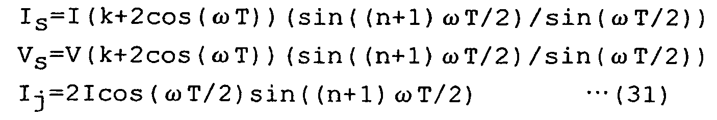
- Then, if the expression (31) is expressed with Zs (size: (Rs 2 + Xs 2)1/2 and phase φ = tan-1(Xs/Rs), expression (32) is established. Therefore, the expression (32) indicates operation principle expression of mho characteristic shown in
FIG. 14 if its frequency is basic frequency.
- The above-described structure indicates a case where voltage vpjm normal to voltage vsm in the fundamental wave is extracted by the polarized
voltage value calculator 12. The present invention is not restricted to this example. For example, it is permissible to provide with a polarizedvoltage value calculator 14 which regards a voltage before predetermined cycles (data before N samplings) of the voltage vjm normal to voltage Vsm as polarized voltage as shown inFIG. 15 . In this case, the voltage vpjm and voltage vsm are indicated in the expression (33).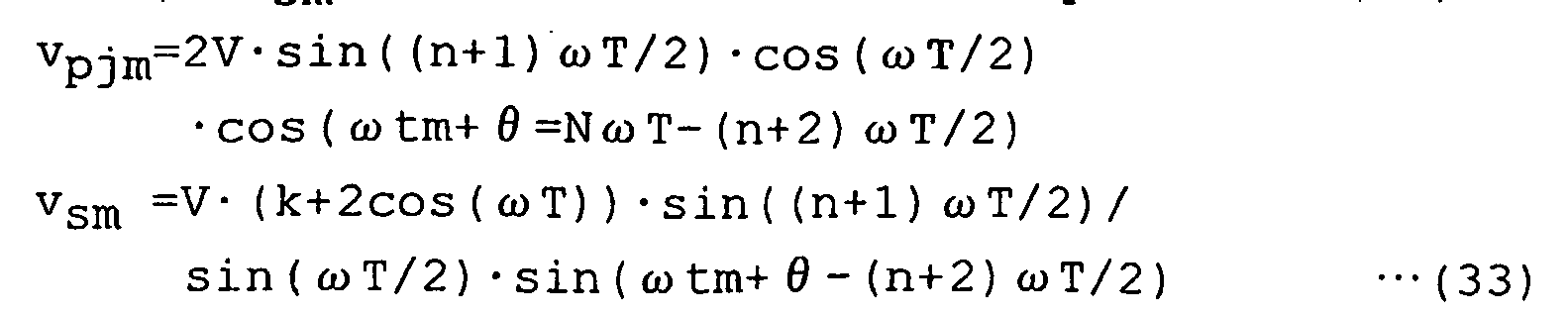
- It is permissible to provide with a polarized
voltage value calculator 15 for extracting voltage vpim normal to voltage vsm as shown inFIG. 16 and if this is for detecting a short-circuit, in case of, for example, AB phase, extract positive sequence voltage relative to the AB phase. A, B, and C indicate each phase of three-phase AC quantity of electricity. - For example, positive sequence voltage relative to the AB phase can be extracted according to vpsm(AB) = -31/2 (vjm(C) - vjm(0)) + vsm(AB). Here, vsm(0) indicates zero phase quantity of electricity.
- Further, if this is for ground fault, the positive sequence voltage relative to A phase can be calculated according to vpsm(A) = 31/2. (vsm(A) - vsm(0) + vjm(BC).
- In addition to the method for extracting voltage vector from two electricity quantities normal to each other, it is permissible to apply a method in which sampling time series is shifted by 90° or equivalent.
- Consequently, amplification of error due to approximation of the differential item is suppressed, so that Lm/L (true value) becomes a characteristic which is as near 1 as possible in a wide frequency band. Therefore, it is possible to block an influence even when a harmonic component occurs in fault voltage and fault current of power system thereby improving reliability.
- A fourth embodiment of the present invention will be described with reference to
FIG. 17 . Description of the same configuration as the above-described embodiments is omitted while like reference numerals are attached thereto. -
FIG. 17 is a block diagram of a protection relay applied to description of this embodiment. According to the fourth embodiment, outputs from thefirst filter 1 and thesecond filter 2 are inputted to a chargingcurrent compensation calculator 16 and its output is inputted to anoperation decision section 18 which follows operation decision principle of ratio differential relay type so as to decide whether or not it is active. - The charging
current compensation calculator 16 corrects a setting value Cs in the form of Cs ← Cs · (k+2cos(ω0T)/sin(ω0T) and calculates ism-Cs · vjm using output current ism from thefirst filter 1 and output voltage vjm from thesecond filter 2. In the meantime, Cs · vjm indicates current compensation generated by charge capacity Cs. - Then, opposing quantity of electricity (ism-Cs · vjm)B of an opposite terminal is received by transmission and
reception section 17 and quantity of electricity of itself terminal is transmitted to the electric power station. Here, B indicates quantity of electricity at an opposite terminal. - After that, the
operation decision section 18 decides the operation based on vectorial sum of current which compensates for charge current at itself terminal obtained by the chargingcurrent compensation calculator 16 and current which compensates for charge current at a terminal of the opposite terminal, namely, scalar sum of amplitude value of differential current and currents which compensate for charge current at each terminal, according to expression (34) :
ka represents a proportion restricting coefficient; and
kb represents minimum sensitivity current. - Physical meaning of the charging current compensation indicated in the expression (34) will be described with reference to a power transmission line in
FIG. 18 . A well known telegraph equation is expressed at transmission/reception terminal as shown in expression (35). Then, if Taylor expansion approximation is executed on differential current iDD (t) with the condition of (τ ≒ 0), the expression (36) is obtained:
Waveform of forward movement:


R represents a receiving terminal;
Z represents a surge impedance =; and
τ represents propagation time = 1/ν (LC) .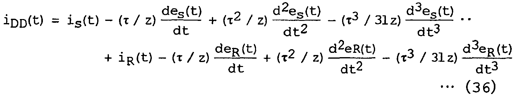
- Even if differential current is extracted with only current vectorial sum current (is(t) + iR(t)) at the transmission/reception terminal, the aforementioned charge current component becomes error current, thereby inducing a drop of sensitivity of the differential relay. Thus, only a fault current component can be extracted by compensating for this.

- In the above description, the transfer function f(Z) in the
first filter 1 and thesecond filter 2 has been described in the form of f(Z) = (1+Z-1+Z-2+ ··· +Z-n). It is evident that the same effect can be obtained even if the transfer function is f(Z) = (1+Z-2+Z-4+ ··· +Z-2n). - In this case, in the expression (10), ωT/2 only should be replaced for ωT and in that case, the expression (38) is established. Likewise, the expressions (8) and (12) only should be replaced. For convenience of following description, it is described that f1 = f(Z) = (1+Z-1+Z-2+ ··· +Z-n), and f2 = f(Z) = (1+Z-2+Z-4+ ··· +Z-2n).

- If f1 is replaced to f2, the quantity of data in the latter can be reduced assuming that the window length of data for use is the same and approximation error of integration is of the same value. For example, if n = 2 is adapted in case of f1, n = 1 may be adapted in case of f2.
- Because gain in the
first filter 1 and thesecond filter 2 using f1 is larger than gain in thefirst filter 1 and thesecond filter 2 using f2, noise error can be compressed by that amount. - For example, when f1 is used, gain G1 of n = 2 is expressed in the expression (39) and if f2 is used, gain G2 of n = 2 is expressed in the expression (40).


- Such transfer function f(Z) is constructed with FIR fileter. The present invention is not restricted to this example, but the same integration error characteristic can be achieved even when it is constructed with recursive digital filter.
- Consequently, amplification of error due to approximation of the differential item is suppressed, so that Lm/L (true value) becomes a characteristic which is as near 1 as possible in a wide frequency band. Therefore, it is possible to block an influence even when a harmonic component occurs in fault voltage and fault current of the power system thereby improving reliability.
- According to the present invention, as described above, even when a harmonic component is overlaid on a fault current and a fault voltage generated upon a fault of a power system, a predetermined time differential equation can be solved approximately by passing through predetermined digital filters normal to each other in a wide frequency band, thereby achieving a high accuracy protection relay.
Claims (9)
- A protection relay for determining whether or not a fault point of a power system exists in a predetermined range, comprising:filter means (1, 2) for inputting sampling data of a voltage and a current in the power system to a digital filter having a predetermined transfer function and outputting a first voltage data and a first current data, and a second voltage data and a second current data normal to the first voltage data and the first current data, respectively;calculation means for calculating a predetermined measurement value based on the first voltage data, the first current data, the second voltage data and the second current data at a first time and the first voltage data, the first current data, the second voltage data and the second current data at a second time different from the first time; andoperation decision means for performing an operation decision based on the predetermined measurement value obtained by the calculation means,wherein the filter means comprises: first filter means for inputting the sampling data to a digital filter having the first transfer function f(Z)·(1+k·Z-1+Z-2) (Z indicates a Z conversion operator) so as to output the first voltage data and current data; and second filter means for inputting the sampling data to a digital filter having the second transfer function f(Z)·(1-Z-2) (Z indicates a Z conversion operator) so as to output the second voltage data and the second current data.
- The protection relay according to claim 1, characterized in that the predetermined measurement value obtained by the calculation means contains at least one of a reactance value and an Ohm value.
- The protection relay according to claim 2, characterized in that the filter means (1, 2) comprises :first filter means (1) for inputting the sampling data vm and im at the first time Tm to a digital filter having transfer function f(Z)·(1+k·Z-1+Z-2) (Z indicates a Z conversion operator) so as to output voltage data vsm and current data ism; and second filter means (2) for inputting the sampling data vm, im at the first time Tm is inputted to a digital filter having transmission f(Z)·(1-Z-2) (Z indicates a Z conversion operator) so as to output voltage data vjm and current data ijm normal to the voltage data vsm and the current data ism.the calculation means calculates a reactance value Xm based on:

using the first voltage data vsm, the first current data ism, the second voltage data vjm and the second current data ijm at the first time tm and the first voltage data vsm-p, the first current data ism-p, the second voltage data vjm-p and the second current data ijm-p at the second time tm-p, andthe operation decision means has an operation decision section which decides the operation based on the reactance value Xm. - The protection relay according to claim 3, characterized in that the operation decision means decides the operation based on a decision expression of Xm ≤ Xs based on the reactance value Xm and a setting value Xs.
- The protection relay according to claim 3, characterized in that the calculation means calculates an Ohm value Rm based on:using the first voltage data vsm, the first current data ism, the second voltage data vjm and the second current data ijm at the first time tm and the first voltage data vsm-p, the first current data ism-p, the second voltage data vjm-p and the second current data i¡m-p at the second time tm-p, the Ohm value Rm is calculated based on
 the operation decision means decides the operation from the reactance value Xm from the calculation means according to a decision expression:where;
 Ro (Ohm component) represents an offset mho near side setting value;Xo (reactance component) represents an offset mho near side setting value;RF (Ohm component) represents an offset mho far side setting value; andXF (reactance component) represents an offset mho far side setting value.
 - The protection relay according to claim 2, characterized in thatthe filter means (1, 2) comprises: first filter means (1) for inputting the sampling data vm and im at the first time Tm to a digital filter having transfer function f(Z)·(1+k·Z-1+Z-2) (Z indicates a Z conversion operator) so as to output voltage data vsm and current data ism; and second filter means (2) for inputting the sampling data vm and im at the first time Tm to a digital filter having transmission f(Z)·(1-Z-2) (Z indicates a Z conversion operator) so as to output voltage data vjm and current data ijm, normal to the voltage data vsm and the current data ism, andthe calculation means calculates an Ohm value Rm using the first and second voltage data vsm, vjm, vsm-p and vjm-p and the first and second current data ism, ijm, ism-p and ijm-p at the first and second times Tm and Tm-p, which are obtained by the first fitter means (1) and second filter means (2), andthe operation decision means decides the operation based on the Ohm value Rm from the calculation means.
- The protection relay according to claim 1 characterized by further comprising:polarized voltage value calculation means for inputting the first and second voltage data and the first and second current data so as to calculate a third voltage normal to the fist voltage;wherein the polarized voltage value calculation means calculates a third voltage vpjm based on the first voltage data vsm, the first current data ism, the second voltage data vjm, and the second current data ijm and
the operation decision means decides the operation based on:
using the third voltage vpjm, the first voltage vsm, the first current data ism, the second voltage data vjm, the second current data ijm at the first time tm and the first voltage data vjm-p, the first current data ijm-p at the second time tm-p and a setting value (Rs, Us). - The protection relay according to claim 7, characterized in that the polarized voltage value calculation means calculates a voltage before predetermined cycles of a voltage normal to the first voltages as the third voltage.
- The protection relay according to claim 1, characterized in that:the first filter means (1) inputs sampling data vm and im of voltage v and current i in the power system to a digital filter so as to output voltage data vsm and current data ism, andthe second filter means (2) in which the sampling data vm, im are inputted to a digital filter outputs voltage data vjm and current data ijm normal to the voltage data vsm and current data ism, further comprises:where,charging current compensation calculation means (16) for calculating quantity of electricity defined in ism-C·vjm by the current data ism, the voltage data vjm, and a setting value Cs at time tm; andtransmission and reception means (17) for transmitting output of the charging current compensation calculation means to an opposite terminal and when quantity of electricity at the opposite terminal is assumed to be B, receiving quantity of electricity defined by (ism-C·vjm)B at the opposite terminal, and whereinthe operation decision means (18) performs an operation decision based on the outputs from the charging current compensation calculation means and the transmission/reception means according to the following expression:
 ∥am∥ represents a quantity parallel to amplitude of AC quantity of electricity "a" at time tm;ka represents a proportion restricting coefficient; andkb represents minimum sensitivity current.
Applications Claiming Priority (2)
| Application Number | Priority Date | Filing Date | Title |
|---|---|---|---|
| JP2001057948A JP2002262447A (en) | 2001-03-02 | 2001-03-02 | Protective relay |
| JP2001057948 | 2001-03-02 |
Publications (4)
| Publication Number | Publication Date |
|---|---|
| EP1237249A2 EP1237249A2 (en) | 2002-09-04 |
| EP1237249A3 EP1237249A3 (en) | 2004-02-04 |
| EP1237249B1 true EP1237249B1 (en) | 2009-08-12 |
| EP1237249B9 EP1237249B9 (en) | 2010-02-03 |
Family
ID=18917748
Family Applications (1)
| Application Number | Title | Priority Date | Filing Date |
|---|---|---|---|
| EP02004755A Expired - Lifetime EP1237249B9 (en) | 2001-03-02 | 2002-03-01 | Protection relay |
Country Status (6)
| Country | Link |
|---|---|
| US (1) | US6906903B2 (en) |
| EP (1) | EP1237249B9 (en) |
| JP (1) | JP2002262447A (en) |
| KR (1) | KR100465945B1 (en) |
| CN (1) | CN1374727B (en) |
| DE (1) | DE60233284D1 (en) |
Families Citing this family (9)
| Publication number | Priority date | Publication date | Assignee | Title |
|---|---|---|---|---|
| JP3857195B2 (en) * | 2002-07-09 | 2006-12-13 | 株式会社東芝 | Distance relay device |
| US7319576B2 (en) * | 2005-08-18 | 2008-01-15 | Schweitzer Engineering Labortories, Inc. | Apparatus and method for providing differential protection for a phase angle regulating transformer in a power system |
| JP5401710B2 (en) * | 2010-03-16 | 2014-01-29 | 株式会社東芝 | Protection relay device and protection relay method |
| US8717725B2 (en) | 2010-12-02 | 2014-05-06 | Schweitzer Engineering Laboratories Inc | Dual-comparator restricted earth fault protection |
| CN103630726B (en) * | 2013-10-30 | 2017-01-25 | 惠州市亿能电子有限公司 | Estimation method of battery polarization voltage in BMS (battery management system) sleep mode |
| EP2908397B1 (en) * | 2014-02-14 | 2017-08-09 | Nse Ag | Method for protecting an electrical supply network |
| CN105572495B (en) * | 2015-11-09 | 2019-08-23 | 上海凌翼动力科技有限公司 | High direct voltage high-current circuit open-circuit fault dynamic analog electronic device |
| CN106324403B (en) * | 2016-08-29 | 2019-03-19 | 国网江苏省电力公司电力科学研究院 | An Adaptive Filtering Algorithm for Relay Protection Based on State Recognition |
| US10938198B2 (en) * | 2018-10-03 | 2021-03-02 | Schweitzer Engineering Laboratories, Inc. | Variable window length filter for protective relaying |
Family Cites Families (8)
| Publication number | Priority date | Publication date | Assignee | Title |
|---|---|---|---|---|
| SE384611B (en) * | 1974-06-20 | 1976-05-10 | Asea Ab | FILTER PROTECTION FOR RELAY PROTECTION |
| US4093977A (en) * | 1976-06-15 | 1978-06-06 | Westinghouse Electric Corp. | Ground fault protective device |
| JPH0828934B2 (en) * | 1984-07-31 | 1996-03-21 | 株式会社東芝 | Protection control device |
| KR950004805B1 (en) * | 1993-02-27 | 1995-05-10 | 현대중공업주식회사 | Digital Relaying Method for Motor Protection of Electronic Switchgear |
| JP3322996B2 (en) * | 1994-07-01 | 2002-09-09 | 東京電力株式会社 | Protection relay method |
| KR20000007462U (en) * | 1998-09-30 | 2000-04-25 | 이해규 | Digital protective relay with automatic detection of operating elements |
| US6473723B1 (en) * | 1999-03-17 | 2002-10-29 | General Electric Company | Mimic high pass filter in a protective relay |
| CN2368206Y (en) * | 1999-04-21 | 2000-03-08 | 国家电力公司南京电力自动化设备总厂 | Microcomputor delay protection device for power equipment |
-
2001
- 2001-03-02 JP JP2001057948A patent/JP2002262447A/en active Pending
-
2002
- 2002-03-01 EP EP02004755A patent/EP1237249B9/en not_active Expired - Lifetime
- 2002-03-01 DE DE60233284T patent/DE60233284D1/en not_active Expired - Lifetime
- 2002-03-01 CN CN021067163A patent/CN1374727B/en not_active Expired - Fee Related
- 2002-03-01 US US10/085,708 patent/US6906903B2/en not_active Expired - Lifetime
- 2002-03-02 KR KR10-2002-0011210A patent/KR100465945B1/en not_active Expired - Lifetime
Also Published As
| Publication number | Publication date |
|---|---|
| US20020149893A1 (en) | 2002-10-17 |
| US6906903B2 (en) | 2005-06-14 |
| KR100465945B1 (en) | 2005-01-13 |
| CN1374727B (en) | 2010-05-26 |
| CN1374727A (en) | 2002-10-16 |
| EP1237249B9 (en) | 2010-02-03 |
| KR20020070899A (en) | 2002-09-11 |
| EP1237249A2 (en) | 2002-09-04 |
| JP2002262447A (en) | 2002-09-13 |
| DE60233284D1 (en) | 2009-09-24 |
| EP1237249A3 (en) | 2004-02-04 |
Similar Documents
| Publication | Publication Date | Title |
|---|---|---|
| US6456947B1 (en) | Digital current differential system | |
| US9461458B2 (en) | Method of distance protection of parallel transmission line | |
| US7106565B2 (en) | Directional ground relay system | |
| US4329727A (en) | Directional power distance relay | |
| US11757282B2 (en) | Method and device for controlling at least one circuit breaker of a power system | |
| EP1237249B1 (en) | Protection relay | |
| CA1198201A (en) | Protective relay apparatus | |
| JP2011015583A (en) | Leakage detection method, leakage detection device, and earth leakage breaker | |
| EP2502318B1 (en) | Fuzzy interference relay and method for current differential protection of a transmission line | |
| EP0718949B1 (en) | Protective relay system with difference filter and addition filter | |
| JP2011227020A (en) | Ground fault detecting system for distribution transformer secondary side | |
| KR100699221B1 (en) | Fault discrimination system and method for mixed transmission line protection | |
| US11962140B2 (en) | Coordination of protective elements in an electric power system | |
| JP4921246B2 (en) | Ground fault distance relay | |
| Johns et al. | A novel non-unit protection scheme based on fault generated high frequency noise on transmission lines | |
| Mao et al. | Protection of Teed transmission circuit using a new directional comparison technique | |
| US20250279255A1 (en) | Protection through a power transformer using compensated voltages and currents | |
| Gajić et al. | Earth-fault protection challenges for modern distribution power systems | |
| CN120414444A (en) | A zero-sequence current protection method for distribution network based on voltage-compensated neutral point insulation | |
| JP3132011B2 (en) | Harmonic filter equipment protection relay | |
| AU6542200A (en) | Digital current differential system | |
| Lai et al. | A new approach to protecting transmission systems with fault generated noise | |
| JPS6124899B2 (en) | ||
| JPS5986418A (en) | Stationary protecting relay |
Legal Events
| Date | Code | Title | Description |
|---|---|---|---|
| PUAI | Public reference made under article 153(3) epc to a published international application that has entered the european phase |
Free format text: ORIGINAL CODE: 0009012 |
|
| 17P | Request for examination filed |
Effective date: 20020301 |
|
| AK | Designated contracting states |
Kind code of ref document: A2 Designated state(s): AT BE CH CY DE DK ES FI FR GB GR IE IT LI LU MC NL PT SE TR |
|
| AX | Request for extension of the european patent |
Free format text: AL;LT;LV;MK;RO;SI |
|
| PUAL | Search report despatched |
Free format text: ORIGINAL CODE: 0009013 |
|
| AK | Designated contracting states |
Kind code of ref document: A3 Designated state(s): AT BE CH CY DE DK ES FI FR GB GR IE IT LI LU MC NL PT SE TR |
|
| AX | Request for extension of the european patent |
Extension state: AL LT LV MK RO SI |
|
| AKX | Designation fees paid |
Designated state(s): DE SE |
|
| 17Q | First examination report despatched |
Effective date: 20070208 |
|
| GRAP | Despatch of communication of intention to grant a patent |
Free format text: ORIGINAL CODE: EPIDOSNIGR1 |
|
| GRAS | Grant fee paid |
Free format text: ORIGINAL CODE: EPIDOSNIGR3 |
|
| GRAA | (expected) grant |
Free format text: ORIGINAL CODE: 0009210 |
|
| AK | Designated contracting states |
Kind code of ref document: B1 Designated state(s): DE SE |
|
| REF | Corresponds to: |
Ref document number: 60233284 Country of ref document: DE Date of ref document: 20090924 Kind code of ref document: P |
|
| REG | Reference to a national code |
Ref country code: SE Ref legal event code: TRGR |
|
| PLBE | No opposition filed within time limit |
Free format text: ORIGINAL CODE: 0009261 |
|
| STAA | Information on the status of an ep patent application or granted ep patent |
Free format text: STATUS: NO OPPOSITION FILED WITHIN TIME LIMIT |
|
| 26N | No opposition filed |
Effective date: 20100517 |
|
| PGFP | Annual fee paid to national office [announced via postgrant information from national office to epo] |
Ref country code: DE Payment date: 20180214 Year of fee payment: 17 |
|
| PGFP | Annual fee paid to national office [announced via postgrant information from national office to epo] |
Ref country code: SE Payment date: 20180313 Year of fee payment: 17 |
|
| REG | Reference to a national code |
Ref country code: DE Ref legal event code: R119 Ref document number: 60233284 Country of ref document: DE |
|
| REG | Reference to a national code |
Ref country code: SE Ref legal event code: EUG |
|
| PG25 | Lapsed in a contracting state [announced via postgrant information from national office to epo] |
Ref country code: SE Free format text: LAPSE BECAUSE OF NON-PAYMENT OF DUE FEES Effective date: 20190302 |
|
| PG25 | Lapsed in a contracting state [announced via postgrant information from national office to epo] |
Ref country code: DE Free format text: LAPSE BECAUSE OF NON-PAYMENT OF DUE FEES Effective date: 20191001 |