EP0718949A1 - Protective relay system with spacial difference filter and summing filter - Google Patents
Protective relay system with spacial difference filter and summing filter Download PDFInfo
- Publication number
- EP0718949A1 EP0718949A1 EP95923544A EP95923544A EP0718949A1 EP 0718949 A1 EP0718949 A1 EP 0718949A1 EP 95923544 A EP95923544 A EP 95923544A EP 95923544 A EP95923544 A EP 95923544A EP 0718949 A1 EP0718949 A1 EP 0718949A1
- Authority
- EP
- European Patent Office
- Prior art keywords
- data
- filter
- voltage
- current
- value
- Prior art date
- Legal status (The legal status is an assumption and is not a legal conclusion. Google has not performed a legal analysis and makes no representation as to the accuracy of the status listed.)
- Granted
Links
Images


Classifications
-
- H—ELECTRICITY
- H02—GENERATION; CONVERSION OR DISTRIBUTION OF ELECTRIC POWER
- H02H—EMERGENCY PROTECTIVE CIRCUIT ARRANGEMENTS
- H02H3/00—Emergency protective circuit arrangements for automatic disconnection directly responsive to an undesired change from normal electric working condition with or without subsequent reconnection ; integrated protection
- H02H3/40—Emergency protective circuit arrangements for automatic disconnection directly responsive to an undesired change from normal electric working condition with or without subsequent reconnection ; integrated protection responsive to ratio of voltage and current
-
- H—ELECTRICITY
- H02—GENERATION; CONVERSION OR DISTRIBUTION OF ELECTRIC POWER
- H02H—EMERGENCY PROTECTIVE CIRCUIT ARRANGEMENTS
- H02H3/00—Emergency protective circuit arrangements for automatic disconnection directly responsive to an undesired change from normal electric working condition with or without subsequent reconnection ; integrated protection
- H02H3/44—Emergency protective circuit arrangements for automatic disconnection directly responsive to an undesired change from normal electric working condition with or without subsequent reconnection ; integrated protection responsive to the rate of change of electrical quantities
Definitions
- This invention relates to a protective relay system provided with a difference filter and an addition filter, and more particularly to a protective relay system substantially free from influence of harmonic components which may be included in a fault current.
- the main technical object of protective relay systems used for protecting the power system is to lessen influence of harmonic components of fault current and fault voltage produced at the time of system failure.
- charge capacity component of the system in equipments or facilities such as cable (power) transmission line and/or phase modifying capacitor, etc.
- phase modifying capacitor, etc. since charge capacity component of the system in equipments or facilities such as cable (power) transmission line and/or phase modifying capacitor, etc. has been increased, the order of harmonic wave produced in the system power has tendency to increase (value twice or three times greater than the fundamental wave).
- FIG. 2 is a graph in which frequency is taken on the abscissa and reactance measured value is taken on the ordinate.
- the line (a) indicates the characteristic in the case where sampling frequency is 600 Hz
- the line (b) indicates the characteristic in the case where sampling frequency is 4800 Hz.
- L m /L (true value) tan ( ⁇ 0 T/2)/tan ( ⁇ T/2)
- i m I ⁇ sin ( ⁇ t m )
- v m V ⁇ sin ( ⁇ t m
- T sampling period
- ⁇ angular frequency
- ⁇ voltage lead phase with respect to current.
- This invention has been made in view of the above-mentioned circumstances, and its object is to provide a protective relay system in which error amplification by differential approximation is suppressed so that there results the characteristic that L m /L (true value) is unlimitedly equal to 1 in broad frequency band, and free from influence of harmonic components produced in fault voltage/fault current of the power system.
- a protective relay system is directed to a protective relay system adapted for detecting, in time series manner, first electric variable (quantity of electricity) and second electric variable of the power system to discriminate on the basis of changes in the respective electric variables in the time series whether or not fault portion (point) of line or equipment included in the power system exists (falls) within a predetermined range thus to protect the power system, the system comprising: digital filter means including a difference filter for outputting first difference electric variable data indicative of difference between at least two sample data of plural sample data of the first electric variable and second difference electric variable data indicative of difference between at least two sample data of plural sample data of the second electric variable at plural sampling times of the time series, and an addition filter for outputting first and second additive electric variable data indicative of data respectively orthogonal to the first and second difference electric variable data in terms of vector; and relay control means for calculating controlled variable of the relay operation in the power system on the basis of the first and second difference electric variable data at a certain sampling time, first and second additive
- the relay control means includes controlled variable calculation means for calculating relay controlled variable including at least one of reactance value, ohm value and operation/suppression quantity on the basis of the voltage data v jm and v jm-p and the current data i jm and i jm-p which are outputs of the difference filter of the digital filter means and the voltage data v sm and v sm-p and the current data i sm and i sm-p which are outputs of the addition filter; and operation judgment means for judging whether or not value of the relay controlled variable calculated by the controlled variable calculation means has a predetermined relationship with respect to a predetermined setting value and constant.
- the controlled variable calculation means is constituted by ohm value calculation means for determining ohm value Rm by the following equation (C) on the basis of the current data i jm and i jm-p which are outputs of the difference filter and the voltage data v sm and v sm-p and the current data i sm and i sm-p which are outputs of the additive filter:
- R m - i jm ⁇ v sm - p + v sm ⁇ i jm - p - i jm ⁇ i sm - p + i jm - p ⁇ i sm
- the operation judgment means judges discriminant "R m ⁇ R s " from the ohm value R m determined by the ohm value calculation means and setting value R s .
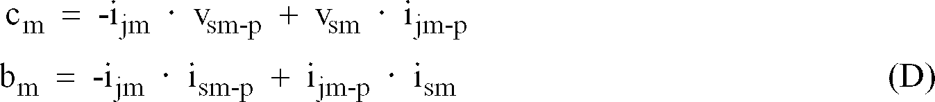
- the controlled variable calculation means is constituted by operation/suppression quantity calculation means corresponding to ohm value by the following equation (D) on the basis of the current data i jm and i jm-p which are outputs of the difference filter and the voltage data v sm and v sm-p and the current data i sm and i sm-p which are outputs of the addition filter:
- c m -i jm ⁇ v sm-p + v sm ⁇ i jm-p
- b m -i jm ⁇ i sm-p + i jm-p ⁇ i sm
- the operation judgment means judges discriminant " b m ⁇ R s -c m ⁇ Kl " from the operation/suppression quantity C m and b m determined by the operation/suppression quantity calculation means
- the polarity voltage preparation means serves to output a voltage earlier by predetermined time of voltage data v jm from the difference filter at the sampling time point t m to the operation judgement means as the polarity voltage v pjm .
- the polarity voltage preparation means serves to synthesize positive phase voltage from output v jm of the difference filter and output v sm of the addition filter with three-phase voltage of the power system at the sampling time tm being as reference to output it as the polarity voltage j pjm to the operation determination means.
- the controlled variable calculation means is composed of charge current compensation means for determining a predetermined electric variable ( i sm - C s ⁇ v jm ) on the basis of the voltage data v jm as output of the difference filter, and the current data i sm as output of the addition filter at the sampling time point t m , and setting value C s ; and transmitting/receiving means adapted for transmitting the predetermined electric variable ( i sm - C s ⁇ v jm ) delivered from the charge current compensation means to a destination electric station (B electric station) where the protective relay system is installed and for receiving electric variable ( i sm - C s ⁇ v jm ) B from any other protective relay system installed in the destination electric station (B electric station), and the operation judgment means serves to judges, on the basis of the predetermined electric variable ( i sm -
- current i' sm at the time point t m is as indicated by the following equation.
- X m V I ⁇ tan( ⁇ T /2) ⁇ sin( ⁇ ) Accordingly, if n is caused to be sufficiently greater value, influence of noise error on the current data of the equation (15) can be lessened, and the frequency characteristic performance with respect to the fundamental wave of X m can satisfy the characteristic of FIG. 2.
- X m /X (value in terms of the fundamental wave) tan ( ⁇ 0 T /2)/tan ( ⁇ T/2) .
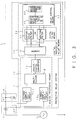
- FIG. 3 is a block diagram showing the entirety of a power system provided in the protective relay system.
- the protective relay system 1 is connected to a transmission line 2 comprising an a.c. power supply 3, a potential transformer (PT) 4 and a current transformer (CT) 5.
- the potential transformer 4 is voltage transformer used for measuring high voltage to measure voltage at a certain point of the transmission line 2.
- the current transformer 5 is an instrument transformer to measure a current at a certain point of the transmission line 2.
- the voltage and the current are the above-described first and second electric variables.
- the protective relay system 1 comprises analog processing means 10 for processing analog data relating to voltage and current measured at plural sampling points continuous in time series manner, and digital protective relay means 15 for carrying out protective relay operation on the basis of digital data obtained by allowing the analog data to undergo analog-digital conversion.
- the analog processing means 10 comprises a voltage sample-hold circuit 11 for detecting, every predetermined sampling time, voltage at a certain point of the transmission line 2 measured by the potential transformer 4, a current sample-hold circuit 12 for detecting, every sampling time, current at a certain point of the transmission line 2 measured by the current transformer 5, a multiplexer 13 for multiplexing or selecting voltage data and current data of time series respectively outputted from the voltage sample-hold circuit 11 and the current sample-hold circuit 12 to output them, and an analog-to-digital converter 14 for converting voltage data and current data delivered from the multiplexer 13 from analog signal to digital signal to deliver it to the digital protective relay system 15.
- the digital protective relay system 15 comprises a memory 16 for temporarily storing respective digital data relating to voltage and current delivered from the analog/digital converter 14 of the analog processing means 10, digital filter means 20 for allowing voltage and current digital data as first and second electric variables delivered from the memory 16 to respectively undergo filtering (processing) to obtain output necessary for control, and relay control means 30 for determining controlled variable of the relay operation on the basis of plural outputs from the digital filter means 20.
- the digital filter means 20 comprises a difference filter 21 for outputting first difference electric variable data which is difference between at least two sample data of plural sample data with respect to voltage as the first electric variable and second difference electric variable data which is difference between at least two sample data of plural data as the second electric variable at plural sampling times of the time series, and an addition filter 22 for outputting first and second additive electric variable data which are data respectively orthogonal to the first and second difference electric variable data in terms of vector.
- the differential filter 21 is a filter in which transfer function "Z -k - Z -q " (Z is Z transform operator, and k ⁇ q) is used to output voltage data v jm and current data i jm which serve as the first and second difference electric variable data at a certain sampling time t m , and voltage data v jm-p and current data i jm-p at any other sampling time t m-p .
- the relay control means 30 comprises controlled variable calculation means 31 for calculating relay controlled variable including at least one of reactance value, ohm value, operation/suppression quantity on the basis of the voltage data V jm and v jm-p and the current data i jm and i jm-p outputs of the difference filter of the digital filter means, and the voltage data v sm and v sm-p and the current data i sm and i sm-p which are outputs of the addition filter, and operation judgment means 32 for judging whether or not the value of the relay controlled variable calculated by the controlled variable calculating means has a predetermined relationship with respect to predetermined setting value and constant.
- the relay control means calculates controlled variable of the relay operation in the power system on the basis of the first and second difference electric variable data at a certain sampling time, first and second additive electric variable data at the certain sampling time, first and second difference electric variable data at any other sampling time, and first and second additive electric variable data at the other sampling time to judge, on the basis of the controlled variable, the operation as to whether or not protection of the power system should be carried out, thus making it possible to control the relay operation of the power system.
- the gist of this invention resides in that there is used digital filter means comprising difference filter 21 using the transfer function "(Z -k - Z -q )" and addition filter 22 operative while correlating with the operational action of the difference filter 21, and using the transfer function " (1+Z -1 +Z -2 + ⁇ + Z -n ) (1+Z -1 ) ".
- the first to ninth embodiments are characterized in that the kinds of controlled variables calculated by using respective outputs of the filters 21, 22 constituting the digital filter means are respectively different in various manners.
- FIG. 4 is a block diagram of the first embodiment for explaining the protective relay system according to the first aspect of this invention This invention is characterized in that a measure is taken such that even if the sampling period is reduced, noise error included in data of differential quantity is not amplified, thereby making it possible to ensure performance of the frequency characteristic indicated by the equation (14).
- reference numeral 21 denotes a digital difference filter for extracting predetermined frequency components of voltage and current of power system (not shown) subject to protection
- reference numeral 22 denotes a digital addition filter for extracting voltage and current orthogonal to output data of the difference filter 21 in terms of vector even with respect to all frequency components.
- reference numeral 31 denotes reactance value calculation means for calculating reactance
- reference numeral 41 denotes operation judgment means for judgment of operation.
- Sample values v m , i m at time t m of voltage v and current i of the power system are inputted to the addition filter 22 of FIG. 4 to allow them to be passed through a filter having transfer function (1+Z -1 +Z -2 + ⁇ +Z -n ) (1+Z -1 ) (Z indicates Z transform operator) to thereby obtain voltage v sm , current i sm .
- the reactance value calculation means 31 calculates reactance value X m on the basis of the following equation (11) from voltage v sm and current i sm obtained at the addition filter 22 and voltage v jm and current i jm obtained at the differential filter at time t m , and voltage v sm-p , current i sm-p obtained from the addition filter 22 and voltage v jm-p and current i jm-p obtained from the differential filter 21 at time t m-p .
- the operation judgment means 41 judges, from the reactance value X m obtained at the reactance value calculation means 31 and setting value X s , whether or not X m ⁇ X s hold to conduct judgment of operation such that if the above relationship holds, the protective relay is in operative state, while it does not hold, the it is inoperative state.
- X m - v sm ⁇ i sm - p + i sm ⁇ v sm - p - i jm ⁇ i sm - p + i jm - p ⁇ i sm
- Functions of respective digital filters are represented by using Z transform operator in a manner as indicated by the following equation.
- this configuration and the configuration of the addition filter 22 can be realized by divisional configuration consisting of three digital filters. Namely, input voltage and current are caused to be first passed through the first filter of the following equation to input its output to two filters, i.e., a second filter and a third filter, thus making it possible to obtain an output equivalent to the differential filter and the additive filter 22.
- the operation judgment means 41 makes a correction as indicated by X m ⁇ X s /tan ( ⁇ 0 ⁇ T/2) by X m calculated at the reactance value calculation means 31, setting value X s and constant tan ( ⁇ 0 T/2) at the fundamental wave determined in advance to judge whether or not the protective relay is operative. It is to be noted that, in the description of the gist of this invention, description of plural collating operations of the operation judgments is omitted here.
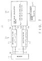
- FIG. 5 is a block diagram showing the configuration of the protective relay system according to the second embodiment of this invention.
- reactance value operation/suppression quantity calculation means 42 for calculating the following equation (17) is applied.
- a m -v sm ⁇ i sm-p +i sm ⁇ v sm-p (17)
- b m -i jm ⁇ i sm-p +i sm-p ⁇ i sm
- the operation judgment means 42 is of a structure to make a correction of reactance setting value X s such that " X s ⁇ X s /tan ( ⁇ 0 T/2) " to carry out judgement of operation on the basis of discriminant expressed as " b m ⁇ X a -a m ⁇ K0 " (K0 is sensitivity constant).
- the protective relay of the second embodiment is protective relay having reactance characteristic similar to FIG. 4, and differs from the system disclosed in the first embodiment of FIG. 4 only in the technique for realization. The reactance characteristic diagram is shown in FIG. 6.
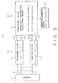
- FIG. 7 is a block diagram showing the configuration of the protective relay system according to the third embodiment corresponding to the third aspect.
- ohm value calculation means 33 for calculating the equation (c) is applied as the controlled variable calculation means 30.
- the operation judgment means 43 is of a structure to judge the relationship in magnitude between the ohm value calculated by the equation (19) and the setting value R s to judge the protective relay to be operative when "R m ⁇ R s " holds.
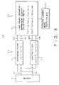
- FIG. 8 is a block diagram showing the configuration of the protective relay system according to the fourth embodiment corresponding to the fourth aspect of this invention.
- ohm value operation/suppression quantity calculation means 34 for calculating the equation (D) is applied as the controlled variable calculation means 30.
- the operation judgment means 44 is of a structure to carry out operation judgment on the basis of b m ⁇ R s -c m ⁇ k1 from ohm setting value Rs, sensitivity constant K1 and outputs c m , b m of the operation/suppression quantity calculation means 34.
- the protective relay of this embodiment is a protective relay having ohm characteristic in a manner similar to FIG. 5, and differs from the system disclosed in the second embodiment only in the technique for realization.
- the ohm characteristic diagram is shown in FIG. 9.
- FIG. 10 is a block diagram showing the configuration of the protective relay system according to the fifth embodiment corresponding to the fifth aspect of this invention.
- the protective relay of the fifth embodiment is combination of the protective relays which have been already described.
- the operation judgment means 45 judges whether or not the protective relay is operative, on the basis of discriminant " (R m -R 0 ) ⁇ (R m -R F )+(X m -X 0 ) ⁇ (X m -X F ) ⁇ 0 " from output Xm of a reactance value calculating means 31A and output Rm of ohm value calculation means 33.
- discriminant " (R m -R 0 ) ⁇ (R m -R F )+(X m -X 0 ) ⁇ (X m -X F ) ⁇ 0 " from output Xm of a reactance value calculating means 31A and output Rm of ohm value calculation means 33.
- R0, X0 and R s , X s are as indicated below.
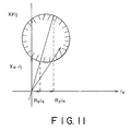
- the protective relay of the fifth embodiment is protective relay having offset mho characteristic.
- the offset mho characteristic diagram is shown in FIG. 11.
- the controlled variable calculation means is comprised of polarity voltage preparation means for preparing polarity voltage v pjm having a predetermined relationship with respect to these voltage data v jm and/or v sm on the basis of the voltage data v jm which is output of the difference filter and voltage data v sm which is output of the addition filter.
- the predetermined relationship is somewhat different in the sixth to eighth embodiments.
- the operation judgment means judges whether or not the following discriminant (F) holds, on the basis of voltage data v jm and current data i jm which are outputs of the difference filter, voltage data vsm and current data i sm which are outputs of the additive filter, polarity voltage v pjm which is output of the polarity voltage preparation means, and setting values R s and X s .
- FIG. 12 is a block diagram showing the configuration of the protective relay system according to the sixth embodiment corresponding to the seventh aspect.
- the protective relay of the sixth embodiment is combination of the protective relay already described.
- the polarity voltage preparation means 36 extracts voltage variable v pjm orthogonal to output vsm of the addition filter in terms of vector as controlled variable calculation means 30.
- the operation judgment means 46 judges, on the basis of the following equation, whether or not, whether or not the protective relay is operative.
- (R s , X s ) are setting values of the ohm component and the reactance component. It is necessary to use X s after undergone correction of X s ⁇ X s /tan( ⁇ 0 T/2) .
- V pj ⁇ ⁇ (R s ⁇ I s ⁇ cos( ⁇ ) + X s /tan ( ⁇ 0 T/2) ⁇ I j ⁇ sin ( ⁇ )) - V s ⁇ ⁇ sin (p ⁇ T) ⁇ K2
- I s , V s and I j are expressed as follows.
- I s 2I ⁇ sin((n+1) ⁇ T/2)/tan( ⁇ T/2)
- V s 2V ⁇ sin((n+1) ⁇ T/2)/tan( ⁇ T/2)
- I j 2I ⁇ sin((n+1) ⁇ T/2)
- the above-mentioned equation eventually the equation of the principle of operation of the mho characteristic.
- the mho characteristic is shown in FIG. 14.
- FIG. 15 is a block diagram showing the configuration of the protective relay system according to the seventh embodiment corresponding to the eighth aspect of this invention.
- operation judgment means 47 is provided in place of the operation judgment means 46 shown in FIG. 12.
- memory voltage earlier by predetermined cycle (data earlier by N samples) of voltage v jm orthogonal to the voltage v sm is caused to be polarity voltage.
- V pjm 2V ⁇ sin((n+1) ⁇ T/2) ⁇ cos( ⁇ t m + ⁇ - N ⁇ T - (n+1) ⁇ T/2
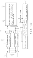
- FIG. 16 is a block diagram showing the configuration of the protective relay system according to the tenth embodiment corresponding to the ninth aspect.
- operation judgment means 48 is provided in place of the operation judgment means 46 shown in FIG. 12.
- voltage v pjm orthogonal to the voltage vsm if that voltage is voltage for detection of short circuit, e.g., in the case of AB phase, positive phase voltage having AB phase as reference is extracted (A, B, C represent respective phases of three-phase a.c. electric variable).
- v pjm (A) 3 1/2 ⁇ v jm (A)-v jm (BC) .
- a method in which the sampling time series is shifted by 90 degrees may be applied.
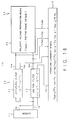
- FIG. 17 is a block diagram showing the configuration of the protective relay system according to the ninth embodiment corresponding to the tenth aspect of this invention.
- Charge current compensation means 35 makes a correction of setting value C s such that C s ⁇ C s /tan( ⁇ 0 T/2) to calculate i sm -C s .v jm from output ism of the additive filter 22 and output v jm of the differential filter 21.
- the C s ⁇ v jm is compensation component of current produced by the charge capacity C s .
- the electric variable " (i sm -C s ⁇ v jm )B " for the destination electric station B is received by transmitting/receiving means 39, and the electric variable of the terminal for source of transmission is transmitted to the B electric station.
- the operation judgment means 49 carries out operation judgment on the basis of the following equation from vector sum current of current obtained by compensating charge current of the terminal for source of transmission provided by the charge current compensation means 35 and current obtained by compensating charge current of the destination electric station B terminal, i.e., scalar sum current of amplitude value of differential current and amplitude of current obtained by compensating charge currents of respective terminals.
- This equation is the operation principle equation of the ratio differential relay system well known as the transmission line differential protective relay ⁇ (i sm C s ⁇ v jm )+(i sm -C s ⁇ v jm B ⁇ ⁇ ka ⁇ i sm -C s ⁇ v jm ⁇ + ⁇ i sm -C s ⁇ v jm )B ⁇ +kb
- the protective relay system even if harmonic components are superimposed on fault current or fault voltage produced at the time of occurrence of failure of the power system, an approach is employed to approximate, with higher accuracy, a predetermined time differential equation by predetermined digital filters of which characteristics are orthogonal to each other in terms of vector in a broad frequency band. Accordingly, there is provided protective relay system of high accuracy free from influence of noise error in failure of the system.
- this protective relay system can be widely applied to power system including various power equipments, particularly equipments such as cable transmission line, phase modifying capacitor and the like.
Landscapes
- Emergency Protection Circuit Devices (AREA)
Abstract
Description
- This invention relates to a protective relay system provided with a difference filter and an addition filter, and more particularly to a protective relay system substantially free from influence of harmonic components which may be included in a fault current.
- The main technical object of protective relay systems used for protecting the power system is to lessen influence of harmonic components of fault current and fault voltage produced at the time of system failure. Particularly, in recent years, since charge capacity component of the system in equipments or facilities such as cable (power) transmission line and/or phase modifying capacitor, etc. has been increased, the order of harmonic wave produced in the system power has tendency to increase (value twice or three times greater than the fundamental wave).
- For this reason, in a method of attenuating harmonic components by filter which has been conventionally applied, it is necessary to prolong delay time of the filter in order to ensure desired attenuation quantity, resulting in delayed operation time of the relay. In order to solve such a problem, there has been conventionally employed an approximation system such that even if any harmonic component is included in the system power, there essentially results no influence of the harmonic wave.
- One example of the system employed at present will be described below.
- In a
transmission line 2 of FIG. 1, assuming now that voltage and current at point A of installation of aprotective relay 1 are respectively v and i when transmission line impedance constants up to the fault point F are such that resistance is R and inductance is L, the differential equation of thetransmission line 2 is expressed by the following equation (1) in the case where fault point (F) voltage is zero. By carrying out approximate calculation of the differential term (di/dt) of this equation (1), it is possible to calculate, with high accuracy, value proportional to inductance L without eliminating harmonic wave by using filter.


- As shown in FIG. 2, it is understood that according as frequency deviates from that of the fundamental wave, value of Lm/L (true value) becomes smaller than 1. This value is permitted to keep value in the vicinity of 1 at values approximately twice or third times greater than the fundamental wave if the value of (ωT/2) is further held down to lower value (the sampling period is reduced). The frequency characteristic when the sampling frequency is set to value eight times greater than the fundamental wave is shown FIG. 2(b). Namely, from a qualitative point of view, the relationship between the differential approximation quantity "im - im-1" and the differentiated quantity "vm + vm-1" are as indicated by the following equations (7) and (8). From these equations, it is indicated that its approximation accuracy is improved.


- When the sampling period


value 30 times greater than the original value.
- This invention has been made in view of the above-mentioned circumstances, and its object is to provide a protective relay system in which error amplification by differential approximation is suppressed so that there results the characteristic that Lm/L (true value) is unlimitedly equal to 1 in broad frequency band, and free from influence of harmonic components produced in fault voltage/fault current of the power system.
- To achieve the above-mentioned object, a protective relay system according to this invention is directed to a protective relay system adapted for detecting, in time series manner, first electric variable (quantity of electricity) and second electric variable of the power system to discriminate on the basis of changes in the respective electric variables in the time series whether or not fault portion (point) of line or equipment included in the power system exists (falls) within a predetermined range thus to protect the power system, the system comprising: digital filter means including a difference filter for outputting first difference electric variable data indicative of difference between at least two sample data of plural sample data of the first electric variable and second difference electric variable data indicative of difference between at least two sample data of plural sample data of the second electric variable at plural sampling times of the time series, and an addition filter for outputting first and second additive electric variable data indicative of data respectively orthogonal to the first and second difference electric variable data in terms of vector; and relay control means for calculating controlled variable of the relay operation in the power system on the basis of the first and second difference electric variable data at a certain sampling time, first and second additive electric variable data at the certain sampling time point, the first and second difference electric variable data at any other sampling time point and the first and second additive electric variable data at the other sampling time point to judge (discriminate), on the basis of the controlled variables, the operation as to whether or not protection of the power system should be carried out.
- In the above-mentioned protective relay system, the difference filter is a filter in which transfer function "


- Further, in the above-mentioned protective relay system, the relay control means includes controlled variable calculation means for calculating relay controlled variable including at least one of reactance value, ohm value and operation/suppression quantity on the basis of the voltage data vjm and vjm-p and the current data ijm and ijm-p which are outputs of the difference filter of the digital filter means and the voltage data vsm and vsm-p and the current data ism and ism-p which are outputs of the addition filter; and operation judgment means for judging whether or not value of the relay controlled variable calculated by the controlled variable calculation means has a predetermined relationship with respect to a predetermined setting value and constant. These components are the fundamental configuration of the protective relay system according to this invention.
- In accordance with the protective relay system according to the first aspect of this invention, in the above-mentioned fundamental configuration, the controlled variable calculation means is constituted by reactance value calculation means for determining reactance value Xm by the following equation (A) on the basis of the current data ijm and ijm-p which are outputs of the difference filter, and the voltage data vsm and vsm-p and the current data ism and ism-p which are outputs of the addition filter


- In accordance with the protective relay system according to the second aspect of this invention, in the above-mentioned configuration, the controlled variable calculation means is constituted by operation/suppression quantity calculation means for calculating operation/suppression quantities am and bm corresponding to reactance value by the following equation (B) on the basis of the current data ijm and ijm-p which are outputs of the difference filter and the voltage data vsm and vsm-p and the current data ism and ism-p which are outputs of the addition filter:


- In accordance with the protective relay system according to the third aspect of this invention, in the above-mentioned fundamental configuration, the controlled variable calculation means is constituted by ohm value calculation means for determining ohm value Rm by the following equation (C) on the basis of the current data ijm and ijm-p which are outputs of the difference filter and the voltage data vsm and vsm-p and the current data ism and ism-p which are outputs of the additive filter:

- In accordance with the protective relay system according to the fourth aspect of this invention, in the fundamental configuration, the controlled variable calculation means is constituted by operation/suppression quantity calculation means corresponding to ohm value by the following equation (D) on the basis of the current data ijm and ijm-p which are outputs of the difference filter and the voltage data vsm and vsm-p and the current data ism and ism-p which are outputs of the addition filter:

- In accordance with the protective relay system according to the fifth aspect of this invention, in the above-mentioned configuration, the controlled variable calculation means is constituted by reactance value calculation means for determining reactance value Xm by the following equation (A) on the basis of the current data ijm and ijm-p which are outputs of the difference filter, and the voltage data vsm and vsm-p and the current data ism and ism-p which are outputs of the addition filter


- where
- R₀ (ohmic component) is the offset mho near side setting value
X₀ (reactance component) is offset mho near side setting value
RF (ohmic component) is the offset mho far side setting value, and
XF (reactance component) is the offset mho far side setting value - In accordance with the protective relay system according to the eighth aspect of this invention, in the above-mentioned sixth aspect, the polarity voltage preparation means serves to output a voltage earlier by predetermined time of voltage data vjm from the difference filter at the sampling time point tm to the operation judgement means as the polarity voltage vpjm.
- In accordance with the protective relay system according to the ninth aspect of this invention, in the above-mentioned sixth aspect, the polarity voltage preparation means serves to synthesize positive phase voltage from output vjm of the difference filter and output vsm of the addition filter with three-phase voltage of the power system at the sampling time tm being as reference to output it as the polarity voltage jpjm to the operation determination means.
- In accordance with the protective relay system according to the tenth aspect of this invention, in the above-mentioned fundamental configuration, the controlled variable calculation means is composed of charge current compensation means for determining a predetermined electric variable (


- where
- ∥am∥ is quantity proportional to amplitude value of a.c. electric variable a at the time point of tm,
- ka
- is No. ratio suppression digits (absolute number), and
- kb
- is minimum sensitively current.
- The fundamental operation of the protective relay system constructed as above will be described below.
- When sample data of current

- Initially, by allowing such sample data to be passed through the digital filter of the first stage (


- Moreover, if value as close as to 1 is selected in the fundamental wave so that quantity which determines magnitudes of the right side of the equation (14) does not become


- As described above, in accordance with this invention, even if harmonic components are superimposed on fault current/voltage produced at the times of failure of the power system, input data is caused to be passed through predetermined digital filters of which characteristics are orthogonal to each other in terms of vector in a broad frequency band, thereby making it possible to approximately solve, with high accuracy, a predetermined differential equation. Thus, high accuracy protective relay system can be realized.
- In the accompanying drawings:
- FIG. 1 is a block circuit diagram showing power system to which a protective relay system according to this invention is applied,
- FIG. 2 is a characteristic diagram showing an example of frequency characteristic of reactance measured value for explaining protective operation in protective relay system according to this invention;
- FIG. 3 is a block diagram showing the fundamental configuration of the protective relay system according to this invention;
- FIG. 4 is a block diagram showing the configuration of the protective relay system according to a first embodiment (first aspect) of this invention;
- FIG. 5 is a block diagram showing the configuration of the protective relay system according to a second embodiment (second aspect) of this invention;
- FIG. 6 is a characteristic diagram showing reactance characteristic on the impedance plane in the protective relay system according to the first and second embodiments of this invention;
- FIG. 7 is a block diagram showing the configuration of the protective relay system according to the third embodiment (third aspect) of this invention;
- FIG. 8 is a block diagram showing the configuration of the protective relay system according to the fourth embodiment (fourth aspect) of this invention;
- FIG. 9 is a characteristic diagram showing ohm characteristic on the impedance plane in the protective relay system according to the fourth embodiment of this invention;
- FIG. 10 is a block diagram showing the configuration of the protective relay system according to a fifth embodiment (fifth aspect) of this invention;
- FIG. 11 is a characteristic diagram showing offset mho characteristic on the impedance plane in the protective relay system according to the fifth embodiment of this invention;
- FIG. 12 is a block diagram showing the protective relay system according to the sixth embodiment (seventh aspect) of this invention;
- FIG. 13 is a characteristic diagram showing the relationship between the maximum sensitivity angle and setting impedance of the mho characteristic in the protective relay system according to the sixth embodiment of this invention;
- FIG. 14 is a characteristic diagram showing mho characteristic in which the relationship shown in FIG. 15 is represented by current reference.
- FIG. 15 is a block diagram showing the configuration of the protective relay system according to the seventh embodiment (eighth aspect) of this invention;
- FIG. 16 is a block diagram showing the configuration of the protective relay system according to an eighth embodiment (ninth aspect) of this invention;
- FIG. 17 is a block diagram sowing the configuration of the protective relay system according to a ninth embodiment (tenth aspect) of this invention; and
- FIG. 18 is a circuit diagram of power transmission line for explaining transmission equation with respect to the charge current compensation in the protective relay system shown in FIG. 17.
- Preferred embodiments of a protective relay system according to this invention will now be described in detail with reference to the attached drawings.
- Prior to description of the embodiments of the protective relay system according to this invention, the fundamental concept of this invention will now be described with reference to FIG. 3.
- FIG. 3 is a block diagram showing the entirety of a power system provided in the protective relay system. In FIG. 3, the
protective relay system 1 is connected to atransmission line 2 comprising an a.c.power supply 3, a potential transformer (PT) 4 and a current transformer (CT) 5. Thepotential transformer 4 is voltage transformer used for measuring high voltage to measure voltage at a certain point of thetransmission line 2. Thecurrent transformer 5 is an instrument transformer to measure a current at a certain point of thetransmission line 2. The voltage and the current are the above-described first and second electric variables. - The
protective relay system 1 comprises analog processing means 10 for processing analog data relating to voltage and current measured at plural sampling points continuous in time series manner, and digital protective relay means 15 for carrying out protective relay operation on the basis of digital data obtained by allowing the analog data to undergo analog-digital conversion. - The analog processing means 10 comprises a voltage sample-hold circuit 11 for detecting, every predetermined sampling time, voltage at a certain point of the
transmission line 2 measured by thepotential transformer 4, a current sample-hold circuit 12 for detecting, every sampling time, current at a certain point of thetransmission line 2 measured by thecurrent transformer 5, amultiplexer 13 for multiplexing or selecting voltage data and current data of time series respectively outputted from the voltage sample-hold circuit 11 and the current sample-hold circuit 12 to output them, and an analog-to-digital converter 14 for converting voltage data and current data delivered from themultiplexer 13 from analog signal to digital signal to deliver it to the digitalprotective relay system 15. - The digital
protective relay system 15 comprises amemory 16 for temporarily storing respective digital data relating to voltage and current delivered from the analog/digital converter 14 of the analog processing means 10, digital filter means 20 for allowing voltage and current digital data as first and second electric variables delivered from thememory 16 to respectively undergo filtering (processing) to obtain output necessary for control, and relay control means 30 for determining controlled variable of the relay operation on the basis of plural outputs from the digital filter means 20. - The digital filter means 20 comprises a difference filter 21 for outputting first difference electric variable data which is difference between at least two sample data of plural sample data with respect to voltage as the first electric variable and second difference electric variable data which is difference between at least two sample data of plural data as the second electric variable at plural sampling times of the time series, and an
addition filter 22 for outputting first and second additive electric variable data which are data respectively orthogonal to the first and second difference electric variable data in terms of vector. In more practical sense, the differential filter 21 is a filter in which transfer function "Z-k - Z-q" (Z is Z transform operator, and k < q) is used to output voltage data vjm and current data ijm which serve as the first and second difference electric variable data at a certain sampling time tm, and voltage data vjm-p and current data ijm-p at any other sampling time tm-p. Moreover, theaddition filter 22 is a filter in which transfer function "


- Further, the relay control means 30 comprises controlled variable calculation means 31 for calculating relay controlled variable including at least one of reactance value, ohm value, operation/suppression quantity on the basis of the voltage data Vjm and vjm-p and the current data ijm and ijm-p outputs of the difference filter of the digital filter means, and the voltage data vsm and vsm-p and the current data ism and ism-p which are outputs of the addition filter, and operation judgment means 32 for judging whether or not the value of the relay controlled variable calculated by the controlled variable calculating means has a predetermined relationship with respect to predetermined setting value and constant. By such a configuration, the relay control means calculates controlled variable of the relay operation in the power system on the basis of the first and second difference electric variable data at a certain sampling time, first and second additive electric variable data at the certain sampling time, first and second difference electric variable data at any other sampling time, and first and second additive electric variable data at the other sampling time to judge, on the basis of the controlled variable, the operation as to whether or not protection of the power system should be carried out, thus making it possible to control the relay operation of the power system.
- The gist of this invention resides in that there is used digital filter means comprising difference filter 21 using the transfer function "(Z-k - Z-q)" and
addition filter 22 operative while correlating with the operational action of the difference filter 21, and using the transfer function "
filters 21, 22 constituting the digital filter means are respectively different in various manners. - Explanation will now be given in detail in connection with digital protective relay means by different configurations caused to corresponding to different kinds of controlled variables, e.g., reactance value, ohm value, respective operation/suppression quantities, polarity voltage, and charge current compensation quantity, etc.
- FIG. 4 is a block diagram of the first embodiment for explaining the protective relay system according to the first aspect of this invention This invention is characterized in that a measure is taken such that even if the sampling period is reduced, noise error included in data of differential quantity is not amplified, thereby making it possible to ensure performance of the frequency characteristic indicated by the equation (14). In FIG. 4, reference numeral 21 denotes a digital difference filter for extracting predetermined frequency components of voltage and current of power system (not shown) subject to protection, and
reference numeral 22 denotes a digital addition filter for extracting voltage and current orthogonal to output data of the difference filter 21 in terms of vector even with respect to all frequency components. Moreover,reference numeral 31 denotes reactance value calculation means for calculating reactance, and reference numeral 41 denotes operation judgment means for judgment of operation. - Sample values vm, im at time tm of voltage v and current i of the power system are inputted to the
addition filter 22 of FIG. 4 to allow them to be passed through a filter having transfer function

- The reactance value calculation means 31 calculates reactance value Xm on the basis of the following equation (11) from voltage vsm and current ism obtained at the
addition filter 22 and voltage vjm and current ijm obtained at the differential filter at time tm, and voltage vsm-p, current ism-p obtained from theaddition filter 22 and voltage vjm-p and current ijm-p obtained from the differential filter 21 at time tm-p. Further, the operation judgment means 41 judges, from the reactance value Xm obtained at the reactance value calculation means 31 and setting value Xs, whether or not Xm ≦ Xs hold to conduct judgment of operation such that if the above relationship holds, the protective relay is in operative state, while it does not hold, the it is inoperative state.
addition filter 22 is lag by 90 degrees with respect to the difference filter 21).

Further, in the case where setting is made such that k=0,
addition filter 22 may be caused to be (

addition filter 22 can be realized by divisional configuration consisting of three digital filters. Namely, input voltage and current are caused to be first passed through the first filter of the following equation to input its output to two filters, i.e., a second filter and a third filter, thus making it possible to obtain an output equivalent to the differential filter and theadditive filter 22. - First filter:
- (
- Second filter:
- (1+Z-1)
- Third filter:
- (1-Z-1)
- The operation judgment means 41 makes a correction as indicated by


- The protective relay system of the second embodiment corresponding to the second aspect will now be described.
- FIG. 5 is a block diagram showing the configuration of the protective relay system according to the second embodiment of this invention.
- In the second embodiment, in place of the reactance value calculation means 41 of FIG. 4, reactance value operation/suppression quantity calculation means 42 for calculating the following equation (17) is applied.

digital filter 20 consisting of difference filter 21 andaddition filter 22 of FIG. 4 are respectively expressed as


- FIG. 7 is a block diagram showing the configuration of the protective relay system according to the third embodiment corresponding to the third aspect.
- In the third embodiment, ohm value calculation means 33 for calculating the equation (c) is applied as the controlled variable calculation means 30.
- In accordance with this equation, when current and voltage inputs of the
digital filter 20 consisting of difference filter 21 andaddition filter 22 of FIG. 4 are respectively expressed as


- FIG. 8 is a block diagram showing the configuration of the protective relay system according to the fourth embodiment corresponding to the fourth aspect of this invention. In the fourth embodiment, ohm value operation/suppression quantity calculation means 34 for calculating the equation (D) is applied as the controlled variable calculation means 30.
- In the fourth embodiment, when current and voltage inputs of
digital filter 20 consisting of differential filter 21 andaddition filter 22 of FIG. 3 are respectively expressed as

- The operation judgment means 44 is of a structure to carry out operation judgment on the basis of

- FIG. 10 is a block diagram showing the configuration of the protective relay system according to the fifth embodiment corresponding to the fifth aspect of this invention. The protective relay of the fifth embodiment is combination of the protective relays which have been already described.
- Namely, this system comprises controlled variable calculation means 30 including reactance value calculation means 31 for carrying out an operation described below,

- The operation judgment means 45 judges whether or not the protective relay is operative, on the basis of discriminant "

- offset mho:
- near side setting value (R₀ (ohm component) X₀ (reactance component)).
far side setting value (RF (ohm component), XF (reactance component)). - The protective relay of the fifth embodiment is protective relay having offset mho characteristic. The offset mho characteristic diagram is shown in FIG. 11.
- The sixth to eighth embodiment of this invention will now be described. These three embodiments respectively correspond to the seventh to ninth aspects, and are conceptually included within the sixth aspect as the higher rank concept.
- Accordingly, the controlled variable calculation means is comprised of polarity voltage preparation means for preparing polarity voltage vpjm having a predetermined relationship with respect to these voltage data vjm and/or vsm on the basis of the voltage data vjm which is output of the difference filter and voltage data vsm which is output of the addition filter. The predetermined relationship is somewhat different in the sixth to eighth embodiments.
- Moreover, the operation judgment means judges whether or not the following discriminant (F) holds, on the basis of voltage data vjm and current data ijm which are outputs of the difference filter, voltage data vsm and current data ism which are outputs of the additive filter, polarity voltage vpjm which is output of the polarity voltage preparation means, and setting values Rs and Xs.


addition filter 22 of the embodiment, the following equation is provided.

R s²+Xs²)1/2 and phase

- FIG. 15 is a block diagram showing the configuration of the protective relay system according to the seventh embodiment corresponding to the eighth aspect of this invention. In FIG. 15, operation judgment means 47 is provided in place of the operation judgment means 46 shown in FIG. 12. In this embodiment, memory voltage earlier by predetermined cycle (data earlier by N samples) of voltage vjm orthogonal to the voltage vsm is caused to be polarity voltage. Namely,

Others are similar to those of FIG. 12. - FIG. 16 is a block diagram showing the configuration of the protective relay system according to the tenth embodiment corresponding to the ninth aspect. In FIG. 16, operation judgment means 48 is provided in place of the operation judgment means 46 shown in FIG. 12. In this embodiment, as voltage vpjm orthogonal to the voltage vsm, if that voltage is voltage for detection of short circuit, e.g., in the case of AB phase, positive phase voltage having AB phase as reference is extracted (A, B, C represent respective phases of three-phase a.c. electric variable). The voltage vpjm can be extracted by

- Moreover, if positive phase voltage is voltage for grounding, the positive phase voltage having A phase as reference can be calculated by

- FIG. 17 is a block diagram showing the configuration of the protective relay system according to the ninth embodiment corresponding to the tenth aspect of this invention. Charge current compensation means 35 makes a correction of setting value Cs such that


additive filter 22 and output vjm of the differential filter 21. The Cs·vjm is compensation component of current produced by the charge capacity Cs. The electric variable "
- The operation judgment means 49 carries out operation judgment on the basis of the following equation from vector sum current of current obtained by compensating charge current of the terminal for source of transmission provided by the charge current compensation means 35 and current obtained by compensating charge current of the destination electric station B terminal, i.e., scalar sum current of amplitude value of differential current and amplitude of current obtained by compensating charge currents of respective terminals. This equation is the operation principle equation of the ratio differential relay system well known as the transmission line differential protective relay

- where
- ∥a∥ indicates quantity proportional to amplitude value of a.c. electric variable a at time point of tm
- Ka
- is No. of ratio suppression digits (absolute number), and
- Kb
- is minimum sensitivity current.
- The physical meaning of the charge current compensation of this equation will be described below with reference to the transmission line of FIG. 18. The well known transmission equation is indicated at the transmitting/receiving terminal.

- where
- suffix s is transmission terminal,
R is charge terminal, - In accordance with the protective relay system according to this invention, even if harmonic components are superimposed on fault current or fault voltage produced at the time of occurrence of failure of the power system, an approach is employed to approximate, with higher accuracy, a predetermined time differential equation by predetermined digital filters of which characteristics are orthogonal to each other in terms of vector in a broad frequency band. Accordingly, there is provided protective relay system of high accuracy free from influence of noise error in failure of the system. Thus, this protective relay system can be widely applied to power system including various power equipments, particularly equipments such as cable transmission line, phase modifying capacitor and the like.
(1/2 of charge capacity of SR entire interval)
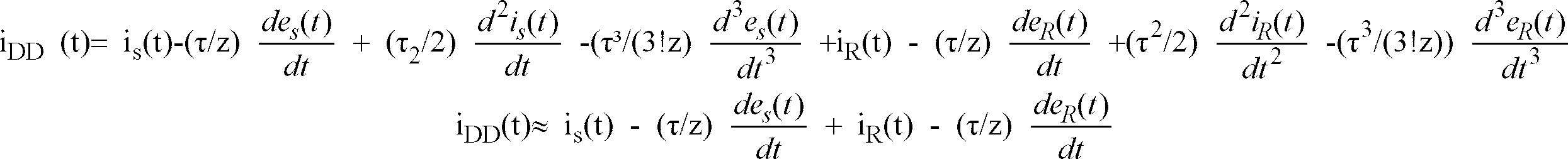
If differential current is extracted only by current vector sum current (is(t)+iR(t)) of the transmitting/receiving terminal, the previously described charge current component would be error current, leading to lowering of sensitivity of the differential relay. Accordingly, such error current is compensated so that only the fault current component can be extracted. It is apparent as previously described that this invention can be applied to the time differential equation of the above-mentioned equation. In addition, it is omitted that the meaning of the ratio differential system is described here.
Claims (13)
- A protective relay system adapted for detecting, in time series manner, first electric variable and second electric variable of the power system to discriminate on the basis of changes in the respective electric values in the time series whether or not fault portion (point) of line or equipment included in the power system exists within a predetermined range,
the system comprising:
digital filter means including a difference filter for outputting first difference electric variable data indicative of difference between at least two sample data of plural sampling data of the first electric variable and second difference electric variable data indicative of
between at least two sample data of plural sample data of the second electric variable at plural sampling times of the time series, and an addition filter for outputting first and second additive electric variable data indicative of data respectively orthogonal to the first and second difference electric variable data in terms of vector; and
relay control means for calculating controlled variables of the relay operation in the power system on the basis of the first and second difference electric variable data at a certain sampling time, first and second additive electric variable data at the certain sampling time point, the first and second difference electric variable data at any other sampling time point and the first and second additive electric variable data at the other sampling time point to judge (discriminate), on the basis of the controlled variables, the operation as to whether not protection of the power system should be carried out. - A protective relay system as set forth in claim 1,
wherein the difference filter is a filter in which transfer function "Z-k-Z-q" (Z is Z transform operator and k < q) is used to output voltage data vjm and current data ijm serving as the first and second difference electric variable data at a certain sampling time tm and voltage data vjm-p and current data ijm-p at any other sampling time tm-p, and the addition filter is a filter in which transfer function "

- A protective relay system as set forth in claim 2,
wherein the relay control means includes
controlled variable calculating means for calculating relay controlled variable including at least one of reactance value, resistance value and operation/suppression quantity on the basis of the voltage data vjm and vjm-p and the current data ijm and ijm-p which are outputs of the difference filter of the digital filter means and the voltage data vsm and vsm-p and the current data ism and ism-p which are outputs of the addition filter thereof; and
operation judging means for judging whether or not value of the relay controlled variable calculated by the controlled variable calculation means has a predetermined relationship with respect to a predetermined setting value and constant. - A protective relay system as set forth in claim 3,
wherein the controlled variable calculation means is constituted by reactance value calculation means for determining reactance value Xm by the following equation (A) on the basis of the current data ijm and ijm-p which are outputs of the differential filter, and the voltage data vsm and vsm-p and the current data ism and ism-p which are outputs of the addition filter
wherein the operation judging means judges the discriminant "Xm ≦ Xs" from reactance value Xm and setting value Xs determined by the reactance calculating means. - A protective relay system as set forth in claim 3,
wherein the controlled variable calculating means is constituted by operation/suppression quantity calculating means for calculating operation/suppression quantities am and bm corresponding to the reactance value by the following equation (B) on the basis of the current data ijm and ijm-p which are outputs of the differential filter and the voltage data vsm and vsm-p and the current data ism and ism-p which are outputs of the additive filter:
wherein the operation judging means judges discriminant "
- A protective relay system as set forth in claim 3,
wherein the controlled variable calculation means is constituted by ohm value calculating means for determining ohm value Rm by the following equation (C) on the basis of the current data ijm and ijm-p which are outputs of the difference filter and the voltage data vsm and vsm-p and the current data ism and ism-p which are outputs of the addition filter:
wherein the operation judgment means judges discriminant "Rm ≦ Rs" from ohm value Rm determined by the ohm value calculating means and setting value Rs. - A protective relay system as set forth in claim 3,
wherein the controlled variable calculating means is constituted by operation/suppression quantity calculating means corresponding to ohm value by the following equation (D) on the basis of the current data ijm and ijm-p which are outputs of the differential filter and the voltage data vsm and vsm-p and the current data ism and ism-p which are outputs of the additive filter: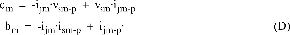
wherein the operation judging means judges discriminant "
- A protective relay system as set forth in claim 3,
wherein the controlled variable calculating means is constituted by reactance value calculating means for determining reactance value Xm by the following equation (A) on the basis of the current data ijm and ijm-p which are outputs of the difference filter, and the voltage data vsm and vsm-p and the current data ism and ism-p which are outputs of the addition filter

wherein the operation judging means serves to discriminate the discriminant (E) on the basis of the reactance value determined by the reactance value calculating means the ohm value Rm determined by the ohm value calculating means: where R₀ (ohmic component) is setting value at the side close to the offset mho,X₀ (reactance component) is setting value at the side close to the offset mho,RF (ohmic component) is setting value at the side remote from the offset mho, andXF (reactance component) is setting value at the side remote from the offset mho.
 - A protective relay system as set forth in claim 3,
wherein the controlled variable calculation means is constituted by polarity voltage preparation means for preparing polarity voltage vpjm having a predetermined relationship with respect to the voltage data vjm and/or vsm on the basis of the voltage data vjm which is output of the difference filter and voltage data vsm which is output of the addition filter, and the operation judgment for judging, on the basis of voltage data vjm and current data ijm which are outputs of the difference filter, voltage data vsm and current data ism which are outputs of the additive filter, polarity voltage Vpjm which is output of the polarity voltage preparation means, and setting values Rs and Xs:
- A protective relay system as set forth in claim 9,
wherein the polarity voltage preparation means synthesizes a voltage orthogonal in a fundamental wave with respect to output vsm of the addition filter in terms of vector to output it as the polarity voltage vpjm to the operation judgment means. - A protective relay system as set forth in claim 9,
wherein the polarity voltage preparation means serves to output a voltage earlier by predetermined time of voltage data vjm from the differential filter at the sampling time point tm to the operation judgement means. - A protective relay system as set forth in claim 9,
wherein the polarity voltage preparation means serves to synthesize positive phase voltage from output vjm of the differential filter and output vsm of the additive filter with three-phase voltage of the power system at the sampling time tm being as reference to output it as the polarity voltage vpjm to the operation determination means. - A protective relay system as set forth in claim 3,
wherein the controlled variable calculation means is composed of:
charge current compensation means for determining predetermined electric variable (


wherein the operation judgment means serves to judges, on the basis of the predetermined electric variable (

 where ∥am∥ is quantity proportional to amplitude value of a.c. electric variable a at the time point of tm,ka is No. ratio suppression digits (absolute number), andkb is minimum sensitivity current.
Applications Claiming Priority (4)
| Application Number | Priority Date | Filing Date | Title |
|---|---|---|---|
| JP17326694 | 1994-07-01 | ||
| JP17326694A JP3322996B2 (en) | 1994-07-01 | 1994-07-01 | Protection relay method |
| JP173266/94 | 1994-07-01 | ||
| PCT/JP1995/001297 WO1996001515A1 (en) | 1994-07-01 | 1995-06-29 | Protective relay system with spacial difference filter and summing filter |
Publications (3)
| Publication Number | Publication Date |
|---|---|
| EP0718949A1 true EP0718949A1 (en) | 1996-06-26 |
| EP0718949A4 EP0718949A4 (en) | 1998-03-04 |
| EP0718949B1 EP0718949B1 (en) | 2001-08-22 |
Family
ID=15957266
Family Applications (1)
| Application Number | Title | Priority Date | Filing Date |
|---|---|---|---|
| EP95923544A Expired - Lifetime EP0718949B1 (en) | 1994-07-01 | 1995-06-29 | Protective relay system with difference filter and addition filter |
Country Status (5)
| Country | Link |
|---|---|
| US (1) | US5796630A (en) |
| EP (1) | EP0718949B1 (en) |
| JP (1) | JP3322996B2 (en) |
| DE (1) | DE69522307T2 (en) |
| WO (1) | WO1996001515A1 (en) |
Cited By (1)
| Publication number | Priority date | Publication date | Assignee | Title |
|---|---|---|---|---|
| EP1237249A3 (en) * | 2001-03-02 | 2004-02-04 | Kabushiki Kaisha Toshiba | Protection relay |
Families Citing this family (9)
| Publication number | Priority date | Publication date | Assignee | Title |
|---|---|---|---|---|
| US6473723B1 (en) * | 1999-03-17 | 2002-10-29 | General Electric Company | Mimic high pass filter in a protective relay |
| JP3830824B2 (en) * | 2002-01-28 | 2006-10-11 | 株式会社東芝 | Digital directional relay |
| JP3857195B2 (en) * | 2002-07-09 | 2006-12-13 | 株式会社東芝 | Distance relay device |
| US8675327B2 (en) * | 2007-03-30 | 2014-03-18 | General Electric Company | Fast impedance protection technique immune to dynamic errors of capacitive voltage transformers |
| US7492298B2 (en) * | 2007-04-09 | 2009-02-17 | Infineon Technologies Ag | System having a signal converter device and method of operating |
| EP2424063B1 (en) * | 2010-08-23 | 2020-09-30 | Nexans | Quench detection system for a superconductor fault current limiter |
| US9007733B2 (en) * | 2011-11-01 | 2015-04-14 | Abb Technology Ag | Travelling-wave based fault protection of high-voltage transmission lines |
| CN103414148A (en) * | 2013-06-21 | 2013-11-27 | 苏州圣元电器有限公司 | Three-phase power supply protection recorder with fault recording function |
| JP7418245B2 (en) * | 2020-03-02 | 2024-01-19 | 三菱電機株式会社 | current differential relay device |
Family Cites Families (9)
| Publication number | Priority date | Publication date | Assignee | Title |
|---|---|---|---|---|
| GB2116792B (en) * | 1982-03-03 | 1985-07-31 | Nat Res Dev | Protection of electrical power supply systems |
| JPS62285512A (en) * | 1986-06-03 | 1987-12-11 | Fuji Electric Co Ltd | Digital filter |
| JPH04161018A (en) * | 1990-10-22 | 1992-06-04 | Nissin Electric Co Ltd | Method of calculating averaged effective value and protective relay using the same |
| JP2682930B2 (en) * | 1992-04-20 | 1997-11-26 | 三菱電機株式会社 | Digital relay device |
| JP3119541B2 (en) * | 1993-03-25 | 2000-12-25 | 株式会社東芝 | Frequency detection method |
| US5455776A (en) * | 1993-09-08 | 1995-10-03 | Abb Power T & D Company Inc. | Automatic fault location system |
| JP3000326B2 (en) * | 1993-09-22 | 2000-01-17 | 株式会社日立製作所 | Digital type distance relay |
| US5506789A (en) * | 1993-10-15 | 1996-04-09 | The Texas A & M University System | Load extraction fault detection system |
| SE502073C2 (en) * | 1994-01-03 | 1995-07-31 | Asea Brown Boveri | Method and apparatus for directional determination of faults on a power line |
-
1994
- 1994-07-01 JP JP17326694A patent/JP3322996B2/en not_active Expired - Fee Related
-
1995
- 1995-06-29 DE DE69522307T patent/DE69522307T2/en not_active Expired - Fee Related
- 1995-06-29 EP EP95923544A patent/EP0718949B1/en not_active Expired - Lifetime
- 1995-06-29 US US08/600,935 patent/US5796630A/en not_active Expired - Lifetime
- 1995-06-29 WO PCT/JP1995/001297 patent/WO1996001515A1/en not_active Ceased
Cited By (3)
| Publication number | Priority date | Publication date | Assignee | Title |
|---|---|---|---|---|
| EP1237249A3 (en) * | 2001-03-02 | 2004-02-04 | Kabushiki Kaisha Toshiba | Protection relay |
| US6906903B2 (en) | 2001-03-02 | 2005-06-14 | Kabushiki Kaisha Toshiba | Protection relay |
| CN1374727B (en) * | 2001-03-02 | 2010-05-26 | 株式会社东芝 | Protective relay device |
Also Published As
| Publication number | Publication date |
|---|---|
| WO1996001515A1 (en) | 1996-01-18 |
| EP0718949B1 (en) | 2001-08-22 |
| DE69522307T2 (en) | 2002-04-25 |
| JPH0819169A (en) | 1996-01-19 |
| JP3322996B2 (en) | 2002-09-09 |
| EP0718949A4 (en) | 1998-03-04 |
| US5796630A (en) | 1998-08-18 |
| DE69522307D1 (en) | 2001-09-27 |
Similar Documents
| Publication | Publication Date | Title |
|---|---|---|
| US6148267A (en) | Method and apparatus for transmission line phase angle comparisons | |
| US4314199A (en) | Method for locating a fault point on a transmission line | |
| US4731689A (en) | Directional detection in connection with faults in a power supply network | |
| US6311307B1 (en) | Digital current differential system | |
| CA1249337A (en) | Line protection | |
| CA1063174A (en) | Method and apparatus for locating a fault on a line | |
| US4063165A (en) | Apparatus for localization of a line fault by using traveling wave signals especially for locating faults both near and far from a measuring location | |
| GB2345810A (en) | Detecting faults on an electrical power line | |
| EP0369577A2 (en) | Apparatus for providing distance protection and distance measurement for a high voltage transmission line | |
| US4261038A (en) | Protection of electrical power supply systems | |
| EP0718949A1 (en) | Protective relay system with spacial difference filter and summing filter | |
| EP0684678B1 (en) | Methods and apparatus for identifying faulted phases on an electric power transmission line | |
| EP1388920A2 (en) | Directional ground relay system | |
| US6633166B1 (en) | Method for generating an error signal identifying a short circuit | |
| US4333151A (en) | Method for protecting an electric power system and digital protective system | |
| US4577254A (en) | Protective relay system | |
| US6046895A (en) | Distance protection method | |
| CN1374727B (en) | Protective relay device | |
| EP0214483B1 (en) | Method for measuring distance in digital distance relays | |
| US6115675A (en) | Double interpolation anti-skew compensation of sampled analog data points in a protective relay | |
| RU2014702C1 (en) | Gear for protection of synchronous generator against fault to ground in one point of excitation circuit | |
| US4755903A (en) | Distance measuring relay for line faults | |
| EP0801745B1 (en) | Measuring method for determining the amplitude and phase of the fundamental tone of an alternating voltage | |
| CA2179249C (en) | Resistive fault location | |
| SU1114986A1 (en) | Device for selective checking of three-phase electric network insulation resistance |
Legal Events
| Date | Code | Title | Description |
|---|---|---|---|
| PUAI | Public reference made under article 153(3) epc to a published international application that has entered the european phase |
Free format text: ORIGINAL CODE: 0009012 |
|
| 17P | Request for examination filed |
Effective date: 19960401 |
|
| AK | Designated contracting states |
Kind code of ref document: A1 Designated state(s): CH DE FR GB LI SE |
|
| A4 | Supplementary search report drawn up and despatched | ||
| AK | Designated contracting states |
Kind code of ref document: A4 Designated state(s): CH DE FR GB LI SE |
|
| GRAG | Despatch of communication of intention to grant |
Free format text: ORIGINAL CODE: EPIDOS AGRA |
|
| RTI1 | Title (correction) |
Free format text: PROTECTIVE RELAY SYSTEM WITH DIFFERENCE FILTER AND ADDITION FILTER |
|
| 17Q | First examination report despatched |
Effective date: 20001004 |
|
| GRAG | Despatch of communication of intention to grant |
Free format text: ORIGINAL CODE: EPIDOS AGRA |
|
| GRAH | Despatch of communication of intention to grant a patent |
Free format text: ORIGINAL CODE: EPIDOS IGRA |
|
| GRAH | Despatch of communication of intention to grant a patent |
Free format text: ORIGINAL CODE: EPIDOS IGRA |
|
| GRAA | (expected) grant |
Free format text: ORIGINAL CODE: 0009210 |
|
| AK | Designated contracting states |
Kind code of ref document: B1 Designated state(s): CH DE FR GB LI SE |
|
| REG | Reference to a national code |
Ref country code: CH Ref legal event code: NV Representative=s name: PATENTANWAELTE FELDMANN & PARTNER AG Ref country code: CH Ref legal event code: EP |
|
| REF | Corresponds to: |
Ref document number: 69522307 Country of ref document: DE Date of ref document: 20010927 |
|
| REG | Reference to a national code |
Ref country code: GB Ref legal event code: IF02 |
|
| ET | Fr: translation filed | ||
| PLBE | No opposition filed within time limit |
Free format text: ORIGINAL CODE: 0009261 |
|
| STAA | Information on the status of an ep patent application or granted ep patent |
Free format text: STATUS: NO OPPOSITION FILED WITHIN TIME LIMIT |
|
| 26N | No opposition filed | ||
| PGFP | Annual fee paid to national office [announced via postgrant information from national office to epo] |
Ref country code: SE Payment date: 20040604 Year of fee payment: 10 |
|
| PGFP | Annual fee paid to national office [announced via postgrant information from national office to epo] |
Ref country code: FR Payment date: 20040608 Year of fee payment: 10 |
|
| PGFP | Annual fee paid to national office [announced via postgrant information from national office to epo] |
Ref country code: GB Payment date: 20040623 Year of fee payment: 10 |
|
| PGFP | Annual fee paid to national office [announced via postgrant information from national office to epo] |
Ref country code: CH Payment date: 20040629 Year of fee payment: 10 |
|
| PGFP | Annual fee paid to national office [announced via postgrant information from national office to epo] |
Ref country code: DE Payment date: 20040708 Year of fee payment: 10 |
|
| PG25 | Lapsed in a contracting state [announced via postgrant information from national office to epo] |
Ref country code: GB Free format text: LAPSE BECAUSE OF NON-PAYMENT OF DUE FEES Effective date: 20050629 |
|
| PG25 | Lapsed in a contracting state [announced via postgrant information from national office to epo] |
Ref country code: SE Free format text: LAPSE BECAUSE OF NON-PAYMENT OF DUE FEES Effective date: 20050630 Ref country code: LI Free format text: LAPSE BECAUSE OF NON-PAYMENT OF DUE FEES Effective date: 20050630 Ref country code: CH Free format text: LAPSE BECAUSE OF NON-PAYMENT OF DUE FEES Effective date: 20050630 |
|
| PG25 | Lapsed in a contracting state [announced via postgrant information from national office to epo] |
Ref country code: DE Free format text: LAPSE BECAUSE OF NON-PAYMENT OF DUE FEES Effective date: 20060103 |
|
| REG | Reference to a national code |
Ref country code: CH Ref legal event code: PL |
|
| EUG | Se: european patent has lapsed | ||
| PG25 | Lapsed in a contracting state [announced via postgrant information from national office to epo] |
Ref country code: FR Free format text: LAPSE BECAUSE OF NON-PAYMENT OF DUE FEES Effective date: 20060228 |
|
| GBPC | Gb: european patent ceased through non-payment of renewal fee |
Effective date: 20050629 |
|
| REG | Reference to a national code |
Ref country code: FR Ref legal event code: ST Effective date: 20060228 |