EP1237227B1 - Stecker für einen elektrischen Leiter - Google Patents
Stecker für einen elektrischen Leiter Download PDFInfo
- Publication number
- EP1237227B1 EP1237227B1 EP02251330A EP02251330A EP1237227B1 EP 1237227 B1 EP1237227 B1 EP 1237227B1 EP 02251330 A EP02251330 A EP 02251330A EP 02251330 A EP02251330 A EP 02251330A EP 1237227 B1 EP1237227 B1 EP 1237227B1
- Authority
- EP
- European Patent Office
- Prior art keywords
- conductor
- connector
- port
- collet
- clamping means
- Prior art date
- Legal status (The legal status is an assumption and is not a legal conclusion. Google has not performed a legal analysis and makes no representation as to the accuracy of the status listed.)
- Expired - Lifetime
Links
- 239000004020 conductor Substances 0.000 title claims abstract description 129
- 230000015572 biosynthetic process Effects 0.000 claims description 8
- 238000005755 formation reaction Methods 0.000 claims description 8
- 230000006835 compression Effects 0.000 claims description 2
- 238000007906 compression Methods 0.000 claims description 2
- 239000000463 material Substances 0.000 description 3
- 238000010008 shearing Methods 0.000 description 3
- 230000000694 effects Effects 0.000 description 2
- 230000005611 electricity Effects 0.000 description 2
- 239000011810 insulating material Substances 0.000 description 2
- 238000007493 shaping process Methods 0.000 description 2
- 238000009413 insulation Methods 0.000 description 1
- 238000000034 method Methods 0.000 description 1
- 230000000750 progressive effect Effects 0.000 description 1
- 230000000007 visual effect Effects 0.000 description 1
- 230000003313 weakening effect Effects 0.000 description 1
Images


Classifications
-
- H—ELECTRICITY
- H01—ELECTRIC ELEMENTS
- H01R—ELECTRICALLY-CONDUCTIVE CONNECTIONS; STRUCTURAL ASSOCIATIONS OF A PLURALITY OF MUTUALLY-INSULATED ELECTRICAL CONNECTING ELEMENTS; COUPLING DEVICES; CURRENT COLLECTORS
- H01R4/00—Electrically-conductive connections between two or more conductive members in direct contact, i.e. touching one another; Means for effecting or maintaining such contact; Electrically-conductive connections having two or more spaced connecting locations for conductors and using contact members penetrating insulation
- H01R4/28—Clamped connections, spring connections
- H01R4/50—Clamped connections, spring connections utilising a cam, wedge, cone or ball also combined with a screw
- H01R4/5016—Clamped connections, spring connections utilising a cam, wedge, cone or ball also combined with a screw using a cone
- H01R4/5025—Clamped connections, spring connections utilising a cam, wedge, cone or ball also combined with a screw using a cone combined with a threaded ferrule operating in a direction parallel to the conductor
-
- H—ELECTRICITY
- H01—ELECTRIC ELEMENTS
- H01R—ELECTRICALLY-CONDUCTIVE CONNECTIONS; STRUCTURAL ASSOCIATIONS OF A PLURALITY OF MUTUALLY-INSULATED ELECTRICAL CONNECTING ELEMENTS; COUPLING DEVICES; CURRENT COLLECTORS
- H01R11/00—Individual connecting elements providing two or more spaced connecting locations for conductive members which are, or may be, thereby interconnected, e.g. end pieces for wires or cables supported by the wire or cable and having means for facilitating electrical connection to some other wire, terminal, or conductive member, blocks of binding posts
- H01R11/03—Individual connecting elements providing two or more spaced connecting locations for conductive members which are, or may be, thereby interconnected, e.g. end pieces for wires or cables supported by the wire or cable and having means for facilitating electrical connection to some other wire, terminal, or conductive member, blocks of binding posts characterised by the relationship between the connecting locations
-
- H—ELECTRICITY
- H01—ELECTRIC ELEMENTS
- H01R—ELECTRICALLY-CONDUCTIVE CONNECTIONS; STRUCTURAL ASSOCIATIONS OF A PLURALITY OF MUTUALLY-INSULATED ELECTRICAL CONNECTING ELEMENTS; COUPLING DEVICES; CURRENT COLLECTORS
- H01R11/00—Individual connecting elements providing two or more spaced connecting locations for conductive members which are, or may be, thereby interconnected, e.g. end pieces for wires or cables supported by the wire or cable and having means for facilitating electrical connection to some other wire, terminal, or conductive member, blocks of binding posts
- H01R11/11—End pieces or tapping pieces for wires, supported by the wire and for facilitating electrical connection to some other wire, terminal or conductive member
- H01R11/32—End pieces with two or more terminations
Definitions
- the invention which is the subject of this application relates to a connector for use in the connection of electrical conductors such as for example the connection of respective ends of conductors, branch connections of conductors.
- a first disadvantage is that the use of the clamping screws means that the length of the connector has to be such so as to accommodate the number of clamping screws which are required to be used and this can mean that the connector is in fact of a length determined mainly or solely by the number of clamping screws.
- the additional length of the connector means that the same can become bulky and, when one considers that the connector is typically required to be fitted in a confined space underground, and often in inclement conditions as, for example, the space may be flooded in wet weather, it will be appreciated that a bulky connector is not a desirable feature.
- a further problem is that there are now a number of different forms of conductors being used in the industry which are of different cross sectional shape and, in many instances, the conventional mechanical conductors are not satisfactory in connecting certain conductor types such as, for example, a conductor with a substantially circular cross section.
- US5573423 discloses a connector which includes a collet arrangement but there is no ability for the user to be able to identify that sufficient clamping force has been exerted on the conductor to secure the same in position. The same problem applies to the clamping arrangement shown in US2341970 .
- US5092797 discloses a separate clamping bolt with a shear facility.
- the aim of the present invention is to provide a mechanical connector for use in the connection of electrical conductors to provide electrical connection between the same and to provide the connector in a form which can be of relatively short length, is easy to fit in confined areas and can be adapted to allow the connection of conductors of different shapes and/or sizes. Furthermore, it is an aim of the present invention to provide a mechanical connector for electrical conductors which can be provided in a manner to match any of the known forms of mechanical connectors in terms of arrangement of the respective conductors which are to be joined together and therefore provide a range of mechanical connectors which can be used in accordance with conventional requirements.
- a connector for the connection of the ends of at least two electrical conductors in an end to end manner to allow electrical connection between the said conductors
- said connector including at least one body portion, said body portion having at least one port at one end thereof for the reception of a conductor end therein, a collet arrangement for location around said conductor and location within said port with the conductor, and a clamping means, positioned around the conductor and engageable with the body portion such that rotatable movement of the clamping means to exert a clamping force with respect to the body portion causes the clamping means to move inwardly of the port and exert a moving action on the collet which causes the same to move to a fixing position in the body portion port with respect to the conductor and/or connector body and causes the collet to exert a gripping action on the conductor and thereby secure the conductor in position within the connector, characterised in that the clamping means includes a shear line which shears when a predetermined clamping torque
- the connector is used to connect a number of conductor ends together although the connection means used for respective conductors may vary and may be in a number of different arrangements. It should therefore be appreciated that the connection arrangement for each conductor may or may not be formed in accordance with the invention.
- the connector includes port openings at each end which extend into the length of the connector body, with a conductor end being introduced into each port opening and secured therein with respective collet and clamping means arrangements in accordance with the invention.
- the body portion includes one port passing along the length thereof with two openings, each receiving a conductor end and clamping arrangement.
- the connector body portion includes two ports, one extending inwardly from each of the body portion ends but not being linked.
- the connector is formed by two connector body portions.
- each body portion is arranged with a port protruding inwardly from one end of each and, at the other end, an engagement formation is provided which, by connection of the mutual engagement formations allow the two body portions to be brought into contact and secured in contact to form the connector.
- the connector has at a first end, a port or number of ports and at a second end, a port or number of ports to allow the connection of more than two conductor ends.
- the collet is formed from one or more components, and, in use, the components are placed on the conductor and positioned in the port with the conductor.
- weakened lines and/or slots are provided at spaced locations on the collet to allow compression of the same during movement and the clamping of the collet on the conductor and connector within the connector body.
- the walls of the port which receives the collet taper inwardly so as to form a substantially frustoconical shape as they depend inwardly of the connector from the port opening.
- the collet when the clamping means is first moved inwardly of the port, the collet is caused to move further inwardly of the port along the conductor but, at the same time, the typically frustoconical shaping of the walls of the port, cause the collet to move inwardly and onto the conductor as the collet moves along to exert greater contact with the conductor. After a period of movement, the collet comes to a position where it can no longer move further along or inwardly of the port and becomes fixed in position with respect to the conductor and port and exerts a gripping action on the conductor.
- the clamping means can be of any suitable form which allows the progressive movement of the same inwardly of the port of the connector body when it is required to clamp the conductor in position within the connector.
- the clamping means is threaded and engages with a thread formed at the opening of the port such that rotation of the clamping means with respect to the connector body causes the same to progressively move inwardly of the port until the collet reaches a fixed position.
- the shearing feature means that when a predetermined selected clamping torque has been reached to cause the required tensile strength to be achieved, a portion of the clamping means shears thereby providing the visual indication required and, yet further, ensuring that the clamping means is not overly inserted into the container body.
- the line of shear and shape of same can be such so as to leave the connector "clean lined" and available for the application of a shroud thereover and/or insulation via a heatshrink material or moulded shroud without risk of the shroud being damaged by the line of shear.
- the clamping means comprises a main portion which is threaded for location with the connector body portion, a shear line and the detachable drive portion.
- the drive portion shears from the main portion of the clamping means, further detachment of the drive portion occurs to cause the same to split and hence be removable from the conductor.
- the shear line is formed so as to cause the splitting of the drive portion to occur or alternatively a separate shear line is included or, yet further, engagement means can be released to allow the drive portion to be detachable from the position round the conductor and hence leave only the main portion of the clamping means which is in contact with the connector body remaining.
- the conductor ends are at least partially encapsulated in insulating material and, prior to the fitting of the connector, a portion of the insulating material at the conductor end is removed to allow the connector to be fitted thereon and bring about the electrical connection.
- the collet can be formed of one piece or formed from a number of components brought together around the conductor.
- the internal faces of the collet may be smooth or may be provided with protrusions thereon to improve the grip into the conductor.
- the inner walls of the collet can be shaped to allow the receipt in a close fitting arrangement of the conductor.
- the inner walls of the collet will be curved in a similar manner so that a substantially circular passage is defined therein, or, if the conductor has a 90° or 120° sector shape, as is also possible in commercial use, the inner walls of the collet can be formed accordingly to receive the conductor in close fitting relationship.
- the inner walls of the collet and/or the body may be so formed as to be range taking inasmuch that they contact with a sufficient surface of the conductor to exert the gripping action thereon, regardless of the particular cross sectional shape of the conductor.
- the connector in accordance with the invention can be range taking and/or adaptable so as to take into account the dimensions and shapes of the conductors to be joined together.
- a clamping means and collet are inserted over and around the end of the conductor, said conductor and collet moved into a port in the connector and the clamping means engaged with and moved inwardly of the port, to move the collet further inwardly of the frustoconically shaped port causing the collet to move onto the conductor as the collet moves along the port to exert greater contact with the conductor, and after a period of movement, the collet comes to a position where it can no longer move longitudinally of the port and further movement of the clamping means inwardly of the port causes at least part of the collet to collapse to exert a gripping action on the conductor.
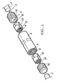
- the connector 4 is shown in section in Figure 2 and comprises a body with a port 6 defined at at least one end.
- the port is provided for the receipt of the conductor end 2 as indicated by arrow 8 and also receipt of a collet 10 which is placed onto the conductor as indicated by the arrow 12.
- the clamping means 16 which will already have been placed around the bared conductor end 2 can be rotated as indicated by arrow 18 so as to engage with a threaded section 20 in the port 6.
- the clamping means is rotated, so it moves inwardly of the port as indicated by arrow 22 to a position as shown in Figure 4 .
- Figure 3A illustrates the formation of the collet before the tightening occurs and the position of the collet after the gripping effect is shown in Figure 3B .
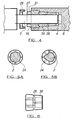
- the clamping means 16 is also provided with a shear line 27, which, upon a predetermined and selected clamping torque being reached when the clamping means is turned, shears as illustrated in Figure 4 .
- the connector collet is in the position and condition as shown in Figures 3b and Figure 4 to exert the required tensile and other clamping forces on the conductor so as to secure the same in the port.
- the shear line 27 is defined by a weakened line with narrower cross section on the clamping means.
- the cross section size and shaping of the shear line 27 is predetermined with respect to the required clamping toque, the size of conductor, shape of the conductor, material used for the clamping means and indeed any relevant detail can be taken into account such that the drive portion 29 of the clamping means will shear off when the selected clamping torque on the collet and conductor is reached. This portion is therefore detachable from the connector leaving the main portion 31 in engagement with the connector and maintaining the clamping torque on the connector.
- Figures 5a and 5b illustrate two forms of collet arrangement and Figure 5 illustrates that regardless of the internal shape of the collet, the external shape will be typically the same so as to allow the same to be acted upon by the inwardly sloping walls of the port 6 in the connector which forces the walls of the collet together and onto the conductor.
- the formations 24 need not always be of the same shape and equally, the cone shaped walls 30 of the collet portions equally need not be the same length at all times and, preferably, will be shortened as much as possible so as to allow the subsequent length of the connector to be shortened.
- Figure 5a illustrates the collet in use to exert a clamping effect on a conductor 2 with a circular cross section.
- Figure 5b illustrates a collet with internal formations to accommodate a conductor 32 in the form of a sector cross section, in this case a 90° sector, conductor.
- the internal area defined by the collet for the reception of the conductor can be formed to suit a particular conductor cross sectional shape.
- the internal surfaces of the collet which are to contact with the conductor to be provided with ridges, teeth or other means which can move into the conductor material to improve the securing of the collet on the conductor during the clamping operation.
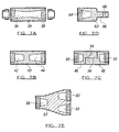
- Figures 7a to 7e illustrate alternative embodiments of the connector in accordance with the invention.
- Figure 7a illustrates a connector body 34 in section with first and second ports 36, 38 which join onto each other and each is for the respective location of a conductor end therein in accordance with the invention.
- Figure 7b illustrates a connector body 40 with ports 42 and 44 which are not linked as shown.
- Figure 7c illustrates a connector body which is formed of two connector parts 46, 48, each connector part having a port 50, 52 respectively for the engagement of a conductor end in accordance with the invention and furthermore, each connector part is provided with an engagement formation 54, 56 which, when brought together as shown, allow the two connector parts to be joined together to form the connector body.
- a clamping means such as a clamping screw, not shown, is passed through the two formations 54, 56 to join the connector parts 46, 48 together.
- Figure 7e illustrates a branch connector body 57 with each of the ports 58, 60, 62 used to receive a conductor end.
- Figure 7d illustrates a terminal conductor body 63 in which the port 64 receives a conductor end which is secured therein in accordance with the invention, and a lug 66 is provided with means 68 to allow the same to be attached to apparatus to which the conductor end is used to supply electricity.
- Figures 8-10 illustrate specific embodiments of a conductor body 100, collet 102 and clamping means 104 respectively.
- Figure 11 illustrates the components of Figures 8 -10 in a fixing position for conductor ends (not shown) to be located in ports 106,106' respectively.
- Figure 12 illustrates how the clamping means 104 can be moved inwardly of the connector body 100 as indicated by arrows 105 to a closed or clamping position. At this stage, continued turning of the clamping means results in the drive portions 129 of the clamping means shearing along shear line 127 and additionally at the same time or thereafter along shear line 133 which is shown in Figure 13 .
- the shear line 133 is provided to ensure that in addition to the drive portion shearing from the main portion 131 of the clamping means at the required clamping torque, the drive portion 129 splits in a manner to ensure that the split parts can be removed from the conductor completely and are not encircling the same.
- the shear lines 127 and 133 can be joined so as to form an integral shear line.
- the form and path of the shear lines 27, 127 and 133 can take any suitable design form, the important requirement being that upon a selected clamping torque being reached, the drive portion shears from the main portion of the clamping means and shears in such as manner so that the drive portion is removable from the conductor.
- the collet can be formed from more than one component, said components placed around the conductor to form the action required and herein described.
Landscapes
- Insulated Conductors (AREA)
- Cable Accessories (AREA)
- Processing Of Terminals (AREA)
- Connections Effected By Soldering, Adhesion, Or Permanent Deformation (AREA)
- Connections By Means Of Piercing Elements, Nuts, Or Screws (AREA)
- Connector Housings Or Holding Contact Members (AREA)
Claims (13)
- Verbinder (4) zur stoßverbindungsweisen Verbindung der Enden (2, 2') von wenigstens zwei elektrischen Leitern, um die elektrische Verbindung zwischen den genannten Leitern zu ermöglichen, wobei der genannte Verbinder wenigstens einen Körperabschnitt aufweist, wobei der genannte Körperabschnitt an einem Ende davon wenigstens einen Kanal (6) zur Aufnahme eines Leiterendes in ihm, eine Spannhülsenanordnung (10) zur Positionierung um den genannten Leiter (2, 2') und zur Positionierung mit dem Leiter in dem genannten Kanal und eine Klemmeinrichtung (16) hat, die um den Leiter (2, 2') positioniert ist und mit dem Körperabschnitt in Eingriff gebracht werden kann, so dass die drehbare Bewegung der Klemmeinrichtung zum Ausüben einer Spannkraft in Bezug auf den Körperabschnitt verursacht, dass sich die Klemmeinrichtung im Kanal einwärts bewegt und eine Bewegungswirkung auf die Spannhülse ausübt, die verursacht, dass sich dieselbe in Bezug auf den Leiter (2, 2') und/oder den Verbinderkörper auf eine Befestigungsposition im Kanal des Körperabschnitts bewegt, und verursacht, dass die Spannhülse (10) eine Festspannwirkung auf den Leiter (2, 2') ausübt und dadurch den Leiter in Solllage in dem Verbinder befestigt, dadurch gekennzeichnet, dass die Klemmeinrichtung eine Scherlinie aufweist, die schert, wenn von der Klemmeinrichtung ein vorbestimmtes Festspannmoment ausgeübt wird, um zu verursachen, dass ein Mitnehmerteil (29) der Klemmeinrichtung davon abgetrennt wird und der genannte Mitnehmerteil um den genannten Leiter und in Bezug auf ihn drehbar ist, wenn er am Rest der Klemmeinrichtung angebracht und wenn er vom Rest der Klemmeinrichtung abgetrennt ist.
- Verbinder nach Anspruch 1, dadurch gekennzeichnet, dass der Verbinder zum Verbinden einer Anzahl von Leiterenden miteinander verwendet wird, mit Kanalöffnungen an jedem Ende, die in die Länge des Verbinderkörpers hinein verlaufen, wobei in jede Kanalöffnung ein Leiterende eingeführt und mit jeweiligen Spannhülsen- und Klemmeinrichtungsanordnungen in ihr befestigt wird.
- Verbinder nach Anspruch 1, dadurch gekennzeichnet, dass der Körperabschnitt einen entlang seiner Länge verlaufenden Kanal aufweist.
- Verbinder nach Anspruch 1, dadurch gekennzeichnet, dass der Verbinderkörperabschnitt zwei Kanäle aufweist, wobei sich einer von jedem der Körperabschnittenden einwärts erstreckt.
- Verbinder nach Anspruch 1, dadurch gekennzeichnet, dass der Verbinder von zwei Verbinderkörperabschnitten gebildet wird, die so angeordnet sind, dass ein Kanal von einem Ende von jedem einwärts vorspringt und am anderen Ende gegenseitige Eingriffsgebilde bereitgestellt sind, die es ermöglichen, dass die zwei Abschnitte zum Bilden des Verbinders miteinander in Kontakt gebracht und befestigt werden.
- Verbinder nach Anspruch 1, dadurch gekennzeichnet, dass der Verbinder an einem ersten Ende einen Kanal oder eine Anzahl von Kanälen und an einem zweiten Ende einen Kanal oder eine Anzahl von Kanälen aufweist, um die Verbindung von mehr als zwei Leiterenden zu ermöglichen.
- Verbinder nach Anspruch 1, dadurch gekennzeichnet, dass der Verbinder an einem Ende mit einer Kanal- und Klemmanordnung und an dem anderen Ende mit einer Einrichtung zum Befestigen des Verbinders an einem Anschluss oder einem anderen Vorrichtungsteil versehen ist.
- Verbinder nach Anspruch 1, dadurch gekennzeichnet, das die Spannhülse von einer Anzahl von Komponenten gebildet wird und die Komponenten im Gebrauch auf dem Leiter platziert und mit dem Leiter im Kanal positioniert werden.
- Verbinder nach Anspruch 1, dadurch gekennzeichnet, dass die Spannhülse geschwächte Linien und/oder Aussparungen aufweist, um das Zusammendrücken derselben während des Festklemmens derselben in Solllage im Verbinderkörper zuzulassen.
- Verbinder nach Anspruch 1, dadurch gekennzeichnet, dass die Spannhülse so gestaltet ist, dass sie Leiter mit unerschiedlicher/n Querschnittsform und/oder Größen in einem bekannten Bereich von Formen und/oder Größen aufnehmen kann.
- Verbinder nach Anspruch 1, dadurch gekennzeichnet, dass die Klemmeinrichtung einen mit dem Körperabschnitt, der Scherlinie und einem Mitnehmerteil versehenen Hauptabschnitt aufweist.
- Verbinder nach Anspruch 1, dadurch gekennzeichnet, dass der Mitnehmerteil beim Abscheren bricht, um vom Leiter entfernt werden zu können.
- Verbinder nach Anspruch 1, dadurch gekennzeichnet, dass die Eingriffeinrichtungen an dem Mitnehmerteil auslösbar sind, damit der Mitnehmerteil vom Leiter entfernt werden kann.
Applications Claiming Priority (2)
| Application Number | Priority Date | Filing Date | Title |
|---|---|---|---|
| GB0104935 | 2001-02-28 | ||
| GBGB0104935.2A GB0104935D0 (en) | 2001-02-28 | 2001-02-28 | Electrical conductor connector |
Publications (3)
| Publication Number | Publication Date |
|---|---|
| EP1237227A2 EP1237227A2 (de) | 2002-09-04 |
| EP1237227A3 EP1237227A3 (de) | 2003-10-29 |
| EP1237227B1 true EP1237227B1 (de) | 2011-11-09 |
Family
ID=9909690
Family Applications (1)
| Application Number | Title | Priority Date | Filing Date |
|---|---|---|---|
| EP02251330A Expired - Lifetime EP1237227B1 (de) | 2001-02-28 | 2002-02-26 | Stecker für einen elektrischen Leiter |
Country Status (4)
| Country | Link |
|---|---|
| EP (1) | EP1237227B1 (de) |
| AT (1) | ATE533204T1 (de) |
| GB (1) | GB0104935D0 (de) |
| HK (1) | HK1046333B (de) |
Cited By (1)
| Publication number | Priority date | Publication date | Assignee | Title |
|---|---|---|---|---|
| CN104347969A (zh) * | 2013-07-25 | 2015-02-11 | 普雷斯曼电缆和系统有限公司 | 用于电力电缆的导体连接器 |
Families Citing this family (5)
| Publication number | Priority date | Publication date | Assignee | Title |
|---|---|---|---|---|
| GB2422966A (en) | 2005-02-04 | 2006-08-09 | Tyco Electronics Ltd Uk | Electrical connector with longitudinally-moving fastener |
| DE102007011096A1 (de) * | 2007-03-07 | 2008-09-11 | Nexans | Anordnung zum Kontaktieren eines Aluminium enthaltenden elektrischen Leiters |
| CN104795646A (zh) * | 2015-04-28 | 2015-07-22 | 国家电网公司 | 可组合式分支连接构件 |
| CN109149153A (zh) * | 2018-09-21 | 2019-01-04 | 广州番禺电缆集团有限公司 | 一种导线连接分流装置 |
| CN113013659B (zh) * | 2019-12-19 | 2023-11-10 | 金风科技股份有限公司 | 防扭连接器、电缆连接装置及风力发电机组 |
Family Cites Families (5)
| Publication number | Priority date | Publication date | Assignee | Title |
|---|---|---|---|---|
| US2341970A (en) | 1943-09-18 | 1944-02-15 | Thexton Mfg Company | Cable clamp |
| FR939596A (fr) * | 1947-01-08 | 1948-11-18 | Système de raccord pour connexions de fils et câbles électriques et toutes autres applications | |
| US2549665A (en) * | 1948-12-01 | 1951-04-17 | John F Conrad | Electric cable connector of the clamping type |
| US5092797A (en) | 1991-07-08 | 1992-03-03 | Amp Incorporated | Electrical wire connector |
| US5573423A (en) | 1995-01-18 | 1996-11-12 | Lin; Kuang-Ts'an | Innovative distribution cable mounting device |
-
2001
- 2001-02-28 GB GBGB0104935.2A patent/GB0104935D0/en not_active Ceased
-
2002
- 2002-02-26 EP EP02251330A patent/EP1237227B1/de not_active Expired - Lifetime
- 2002-02-26 AT AT02251330T patent/ATE533204T1/de active
- 2002-10-08 HK HK02107344.6A patent/HK1046333B/en not_active IP Right Cessation
Cited By (2)
| Publication number | Priority date | Publication date | Assignee | Title |
|---|---|---|---|---|
| CN104347969A (zh) * | 2013-07-25 | 2015-02-11 | 普雷斯曼电缆和系统有限公司 | 用于电力电缆的导体连接器 |
| CN104347969B (zh) * | 2013-07-25 | 2018-12-21 | 普雷斯曼电缆和系统有限公司 | 用于电力电缆的导体连接器 |
Also Published As
| Publication number | Publication date |
|---|---|
| HK1046333B (en) | 2012-05-25 |
| ATE533204T1 (de) | 2011-11-15 |
| EP1237227A2 (de) | 2002-09-04 |
| HK1046333A1 (en) | 2003-01-03 |
| EP1237227A3 (de) | 2003-10-29 |
| GB0104935D0 (en) | 2001-04-18 |
Similar Documents
| Publication | Publication Date | Title |
|---|---|---|
| US3963322A (en) | Torque controlling set screw for use with the cable of solderless connectors, or the like | |
| US9577351B2 (en) | Spring loaded insulation piercing electrical connector | |
| US8157603B2 (en) | Electrical screw terminal, block comprising one such electrical terminal and electrical apparatus comprising one such terminal block | |
| JP5237302B2 (ja) | 電気組継ぎ(splice)コネクタ | |
| US4199216A (en) | Torque controlling set screw for use with the cable of solderless connectors, or the like | |
| US4940856A (en) | Electrical connector | |
| US6979236B1 (en) | Wedge connector assembly | |
| EP1237227B1 (de) | Stecker für einen elektrischen Leiter | |
| US4845312A (en) | Electrical outlet box and outlet therefor | |
| EP0432957A1 (de) | Werkzeug zum Abnehmen von Schichten eines Koaxialkabels | |
| JP2007503683A (ja) | ケーブル接続システム | |
| CA2379840A1 (en) | No-crimp electrical connector side-by-side type | |
| EP2128932A2 (de) | Elektrischer Verbinder mit mechanischer Kompression für elektrische Leiter | |
| GB2286728A (en) | Electrical connector | |
| EP3490069B1 (de) | Leistungsanschluss | |
| US5401194A (en) | Cable clamp with reduced fastener length | |
| US5338222A (en) | Clamping assembly for electrical cables | |
| US2910525A (en) | Solderless connector | |
| EP4302365B1 (de) | Isolationsdurchdringender keilverbinder | |
| CN201084853Y (zh) | 同轴电缆用末端接头 | |
| AU2006241314B2 (en) | Electrical connector with power socket | |
| US1012102A (en) | Coupling. | |
| CN212968465U (zh) | 一种制作bv导线羊眼圈的工具 | |
| EP1844525B1 (de) | Elektrischer steckverbinder | |
| JP2001266971A (ja) | 防水型分岐コネクター |
Legal Events
| Date | Code | Title | Description |
|---|---|---|---|
| PUAI | Public reference made under article 153(3) epc to a published international application that has entered the european phase |
Free format text: ORIGINAL CODE: 0009012 |
|
| AK | Designated contracting states |
Kind code of ref document: A2 Designated state(s): AT BE CH CY DE DK ES FI FR GB GR IE IT LI LU MC NL PT SE TR |
|
| AX | Request for extension of the european patent |
Free format text: AL;LT;LV;MK;RO;SI |
|
| PUAL | Search report despatched |
Free format text: ORIGINAL CODE: 0009013 |
|
| AK | Designated contracting states |
Kind code of ref document: A3 Designated state(s): AT BE CH CY DE DK ES FI FR GB GR IE IT LI LU MC NL PT SE TR |
|
| AX | Request for extension of the european patent |
Extension state: AL LT LV MK RO SI |
|
| 17P | Request for examination filed |
Effective date: 20040329 |
|
| AKX | Designation fees paid |
Designated state(s): AT BE CH CY DE DK ES FI FR GB GR IE IT LI LU MC NL PT SE TR |
|
| 17Q | First examination report despatched |
Effective date: 20090421 |
|
| GRAP | Despatch of communication of intention to grant a patent |
Free format text: ORIGINAL CODE: EPIDOSNIGR1 |
|
| GRAS | Grant fee paid |
Free format text: ORIGINAL CODE: EPIDOSNIGR3 |
|
| GRAA | (expected) grant |
Free format text: ORIGINAL CODE: 0009210 |
|
| AK | Designated contracting states |
Kind code of ref document: B1 Designated state(s): AT BE CH CY DE DK ES FI FR GB GR IE IT LI LU MC NL PT SE TR |
|
| REG | Reference to a national code |
Ref country code: GB Ref legal event code: FG4D |
|
| REG | Reference to a national code |
Ref country code: CH Ref legal event code: EP |
|
| REG | Reference to a national code |
Ref country code: IE Ref legal event code: FG4D |
|
| REG | Reference to a national code |
Ref country code: NL Ref legal event code: T3 |
|
| REG | Reference to a national code |
Ref country code: DE Ref legal event code: R096 Ref document number: 60241493 Country of ref document: DE Effective date: 20120119 |
|
| REG | Reference to a national code |
Ref country code: SE Ref legal event code: TRGR |
|
| REG | Reference to a national code |
Ref country code: HK Ref legal event code: GR Ref document number: 1046333 Country of ref document: HK |
|
| PG25 | Lapsed in a contracting state [announced via postgrant information from national office to epo] |
Ref country code: GR Free format text: LAPSE BECAUSE OF FAILURE TO SUBMIT A TRANSLATION OF THE DESCRIPTION OR TO PAY THE FEE WITHIN THE PRESCRIBED TIME-LIMIT Effective date: 20120210 Ref country code: PT Free format text: LAPSE BECAUSE OF FAILURE TO SUBMIT A TRANSLATION OF THE DESCRIPTION OR TO PAY THE FEE WITHIN THE PRESCRIBED TIME-LIMIT Effective date: 20120309 |
|
| PG25 | Lapsed in a contracting state [announced via postgrant information from national office to epo] |
Ref country code: CY Free format text: LAPSE BECAUSE OF FAILURE TO SUBMIT A TRANSLATION OF THE DESCRIPTION OR TO PAY THE FEE WITHIN THE PRESCRIBED TIME-LIMIT Effective date: 20111109 |
|
| PG25 | Lapsed in a contracting state [announced via postgrant information from national office to epo] |
Ref country code: DK Free format text: LAPSE BECAUSE OF FAILURE TO SUBMIT A TRANSLATION OF THE DESCRIPTION OR TO PAY THE FEE WITHIN THE PRESCRIBED TIME-LIMIT Effective date: 20111109 |
|
| PLBE | No opposition filed within time limit |
Free format text: ORIGINAL CODE: 0009261 |
|
| STAA | Information on the status of an ep patent application or granted ep patent |
Free format text: STATUS: NO OPPOSITION FILED WITHIN TIME LIMIT |
|
| PG25 | Lapsed in a contracting state [announced via postgrant information from national office to epo] |
Ref country code: MC Free format text: LAPSE BECAUSE OF NON-PAYMENT OF DUE FEES Effective date: 20120229 |
|
| REG | Reference to a national code |
Ref country code: CH Ref legal event code: PL |
|
| 26N | No opposition filed |
Effective date: 20120810 |
|
| PG25 | Lapsed in a contracting state [announced via postgrant information from national office to epo] |
Ref country code: CH Free format text: LAPSE BECAUSE OF NON-PAYMENT OF DUE FEES Effective date: 20120229 Ref country code: LI Free format text: LAPSE BECAUSE OF NON-PAYMENT OF DUE FEES Effective date: 20120229 |
|
| REG | Reference to a national code |
Ref country code: IE Ref legal event code: MM4A |
|
| REG | Reference to a national code |
Ref country code: DE Ref legal event code: R097 Ref document number: 60241493 Country of ref document: DE Effective date: 20120810 |
|
| PG25 | Lapsed in a contracting state [announced via postgrant information from national office to epo] |
Ref country code: IE Free format text: LAPSE BECAUSE OF NON-PAYMENT OF DUE FEES Effective date: 20120226 |
|
| PG25 | Lapsed in a contracting state [announced via postgrant information from national office to epo] |
Ref country code: ES Free format text: LAPSE BECAUSE OF FAILURE TO SUBMIT A TRANSLATION OF THE DESCRIPTION OR TO PAY THE FEE WITHIN THE PRESCRIBED TIME-LIMIT Effective date: 20120220 |
|
| PG25 | Lapsed in a contracting state [announced via postgrant information from national office to epo] |
Ref country code: FI Free format text: LAPSE BECAUSE OF FAILURE TO SUBMIT A TRANSLATION OF THE DESCRIPTION OR TO PAY THE FEE WITHIN THE PRESCRIBED TIME-LIMIT Effective date: 20111109 |
|
| PGFP | Annual fee paid to national office [announced via postgrant information from national office to epo] |
Ref country code: SE Payment date: 20131211 Year of fee payment: 13 |
|
| PGFP | Annual fee paid to national office [announced via postgrant information from national office to epo] |
Ref country code: NL Payment date: 20131210 Year of fee payment: 13 |
|
| PGFP | Annual fee paid to national office [announced via postgrant information from national office to epo] |
Ref country code: BE Payment date: 20131210 Year of fee payment: 13 |
|
| PG25 | Lapsed in a contracting state [announced via postgrant information from national office to epo] |
Ref country code: TR Free format text: LAPSE BECAUSE OF FAILURE TO SUBMIT A TRANSLATION OF THE DESCRIPTION OR TO PAY THE FEE WITHIN THE PRESCRIBED TIME-LIMIT Effective date: 20111109 |
|
| PGFP | Annual fee paid to national office [announced via postgrant information from national office to epo] |
Ref country code: DE Payment date: 20131210 Year of fee payment: 13 |
|
| PG25 | Lapsed in a contracting state [announced via postgrant information from national office to epo] |
Ref country code: LU Free format text: LAPSE BECAUSE OF NON-PAYMENT OF DUE FEES Effective date: 20120226 |
|
| PGFP | Annual fee paid to national office [announced via postgrant information from national office to epo] |
Ref country code: IT Payment date: 20140218 Year of fee payment: 13 Ref country code: AT Payment date: 20131210 Year of fee payment: 13 Ref country code: FR Payment date: 20131210 Year of fee payment: 13 |
|
| PG25 | Lapsed in a contracting state [announced via postgrant information from national office to epo] |
Ref country code: BE Free format text: LAPSE BECAUSE OF NON-PAYMENT OF DUE FEES Effective date: 20150228 |
|
| REG | Reference to a national code |
Ref country code: DE Ref legal event code: R119 Ref document number: 60241493 Country of ref document: DE |
|
| REG | Reference to a national code |
Ref country code: NL Ref legal event code: V1 Effective date: 20150901 |
|
| REG | Reference to a national code |
Ref country code: SE Ref legal event code: EUG |
|
| PG25 | Lapsed in a contracting state [announced via postgrant information from national office to epo] |
Ref country code: NL Free format text: LAPSE BECAUSE OF NON-PAYMENT OF DUE FEES Effective date: 20150901 |
|
| REG | Reference to a national code |
Ref country code: AT Ref legal event code: MM01 Ref document number: 533204 Country of ref document: AT Kind code of ref document: T Effective date: 20150226 |
|
| REG | Reference to a national code |
Ref country code: FR Ref legal event code: ST Effective date: 20151030 |
|
| PG25 | Lapsed in a contracting state [announced via postgrant information from national office to epo] |
Ref country code: AT Free format text: LAPSE BECAUSE OF NON-PAYMENT OF DUE FEES Effective date: 20150226 Ref country code: SE Free format text: LAPSE BECAUSE OF NON-PAYMENT OF DUE FEES Effective date: 20150227 |
|
| PG25 | Lapsed in a contracting state [announced via postgrant information from national office to epo] |
Ref country code: IT Free format text: LAPSE BECAUSE OF NON-PAYMENT OF DUE FEES Effective date: 20150226 |
|
| PG25 | Lapsed in a contracting state [announced via postgrant information from national office to epo] |
Ref country code: DE Free format text: LAPSE BECAUSE OF NON-PAYMENT OF DUE FEES Effective date: 20150901 |
|
| PG25 | Lapsed in a contracting state [announced via postgrant information from national office to epo] |
Ref country code: FR Free format text: LAPSE BECAUSE OF NON-PAYMENT OF DUE FEES Effective date: 20150302 |
|
| PGFP | Annual fee paid to national office [announced via postgrant information from national office to epo] |
Ref country code: GB Payment date: 20210107 Year of fee payment: 20 |
|
| REG | Reference to a national code |
Ref country code: GB Ref legal event code: PE20 Expiry date: 20220225 |
|
| PG25 | Lapsed in a contracting state [announced via postgrant information from national office to epo] |
Ref country code: GB Free format text: LAPSE BECAUSE OF EXPIRATION OF PROTECTION Effective date: 20220225 |