EP1237220A2 - Polymer electrolyte membrane fuel cell - Google Patents
Polymer electrolyte membrane fuel cell Download PDFInfo
- Publication number
- EP1237220A2 EP1237220A2 EP02004684A EP02004684A EP1237220A2 EP 1237220 A2 EP1237220 A2 EP 1237220A2 EP 02004684 A EP02004684 A EP 02004684A EP 02004684 A EP02004684 A EP 02004684A EP 1237220 A2 EP1237220 A2 EP 1237220A2
- Authority
- EP
- European Patent Office
- Prior art keywords
- fuel cell
- fuel
- membrane
- electrode
- polymer electrolyte
- Prior art date
- Legal status (The legal status is an assumption and is not a legal conclusion. Google has not performed a legal analysis and makes no representation as to the accuracy of the status listed.)
- Withdrawn
Links
- 239000000446 fuel Substances 0.000 title claims abstract description 138
- 239000012528 membrane Substances 0.000 title claims abstract description 61
- 239000005518 polymer electrolyte Substances 0.000 title claims abstract description 29
- 239000003054 catalyst Substances 0.000 claims description 25
- 239000002245 particle Substances 0.000 claims description 16
- OKTJSMMVPCPJKN-UHFFFAOYSA-N Carbon Chemical compound [C] OKTJSMMVPCPJKN-UHFFFAOYSA-N 0.000 claims description 9
- 229910052799 carbon Inorganic materials 0.000 claims description 9
- 239000007800 oxidant agent Substances 0.000 claims description 7
- 239000000463 material Substances 0.000 claims description 5
- OKKJLVBELUTLKV-UHFFFAOYSA-N Methanol Chemical compound OC OKKJLVBELUTLKV-UHFFFAOYSA-N 0.000 description 39
- BASFCYQUMIYNBI-UHFFFAOYSA-N platinum Chemical compound [Pt] BASFCYQUMIYNBI-UHFFFAOYSA-N 0.000 description 28
- 229910052697 platinum Inorganic materials 0.000 description 14
- 239000003792 electrolyte Substances 0.000 description 12
- 238000000034 method Methods 0.000 description 12
- QAOWNCQODCNURD-UHFFFAOYSA-N Sulfuric acid Chemical compound OS(O)(=O)=O QAOWNCQODCNURD-UHFFFAOYSA-N 0.000 description 8
- 239000007789 gas Substances 0.000 description 8
- 239000000126 substance Substances 0.000 description 8
- NBIIXXVUZAFLBC-UHFFFAOYSA-N Phosphoric acid Chemical compound OP(O)(O)=O NBIIXXVUZAFLBC-UHFFFAOYSA-N 0.000 description 6
- HEMHJVSKTPXQMS-UHFFFAOYSA-M Sodium hydroxide Chemical compound [OH-].[Na+] HEMHJVSKTPXQMS-UHFFFAOYSA-M 0.000 description 6
- QVGXLLKOCUKJST-UHFFFAOYSA-N atomic oxygen Chemical compound [O] QVGXLLKOCUKJST-UHFFFAOYSA-N 0.000 description 6
- 239000001301 oxygen Substances 0.000 description 6
- 229910052760 oxygen Inorganic materials 0.000 description 6
- 238000007747 plating Methods 0.000 description 6
- 239000000243 solution Substances 0.000 description 5
- KWYUFKZDYYNOTN-UHFFFAOYSA-M Potassium hydroxide Chemical compound [OH-].[K+] KWYUFKZDYYNOTN-UHFFFAOYSA-M 0.000 description 4
- 239000007788 liquid Substances 0.000 description 4
- 229910052751 metal Inorganic materials 0.000 description 4
- 239000002184 metal Substances 0.000 description 4
- 239000011259 mixed solution Substances 0.000 description 4
- 239000000203 mixture Substances 0.000 description 4
- 229910000147 aluminium phosphate Inorganic materials 0.000 description 3
- 238000010276 construction Methods 0.000 description 3
- 239000002737 fuel gas Substances 0.000 description 3
- 229920000642 polymer Polymers 0.000 description 3
- 229920005597 polymer membrane Polymers 0.000 description 3
- 229920003935 Flemion® Polymers 0.000 description 2
- UFHFLCQGNIYNRP-UHFFFAOYSA-N Hydrogen Chemical compound [H][H] UFHFLCQGNIYNRP-UHFFFAOYSA-N 0.000 description 2
- KDLHZDBZIXYQEI-UHFFFAOYSA-N Palladium Chemical compound [Pd] KDLHZDBZIXYQEI-UHFFFAOYSA-N 0.000 description 2
- 229910000929 Ru alloy Inorganic materials 0.000 description 2
- 239000002253 acid Substances 0.000 description 2
- 239000003513 alkali Substances 0.000 description 2
- 239000011248 coating agent Substances 0.000 description 2
- 238000000576 coating method Methods 0.000 description 2
- 238000010586 diagram Methods 0.000 description 2
- 238000005516 engineering process Methods 0.000 description 2
- 239000001257 hydrogen Substances 0.000 description 2
- 229910052739 hydrogen Inorganic materials 0.000 description 2
- 150000002739 metals Chemical class 0.000 description 2
- CFQCIHVMOFOCGH-UHFFFAOYSA-N platinum ruthenium Chemical compound [Ru].[Pt] CFQCIHVMOFOCGH-UHFFFAOYSA-N 0.000 description 2
- 229910000033 sodium borohydride Inorganic materials 0.000 description 2
- 239000012279 sodium borohydride Substances 0.000 description 2
- 239000000725 suspension Substances 0.000 description 2
- HYZJCKYKOHLVJF-UHFFFAOYSA-N 1H-benzimidazole Chemical compound C1=CC=C2NC=NC2=C1 HYZJCKYKOHLVJF-UHFFFAOYSA-N 0.000 description 1
- MYMOFIZGZYHOMD-UHFFFAOYSA-N Dioxygen Chemical compound O=O MYMOFIZGZYHOMD-UHFFFAOYSA-N 0.000 description 1
- KJTLSVCANCCWHF-UHFFFAOYSA-N Ruthenium Chemical compound [Ru] KJTLSVCANCCWHF-UHFFFAOYSA-N 0.000 description 1
- 229920002125 Sokalan® Polymers 0.000 description 1
- 239000003011 anion exchange membrane Substances 0.000 description 1
- 230000015572 biosynthetic process Effects 0.000 description 1
- 230000002860 competitive effect Effects 0.000 description 1
- 230000008878 coupling Effects 0.000 description 1
- 238000010168 coupling process Methods 0.000 description 1
- 238000005859 coupling reaction Methods 0.000 description 1
- 238000000151 deposition Methods 0.000 description 1
- 229910001882 dioxygen Inorganic materials 0.000 description 1
- 238000005868 electrolysis reaction Methods 0.000 description 1
- 239000011532 electronic conductor Substances 0.000 description 1
- -1 for example Substances 0.000 description 1
- 150000002431 hydrogen Chemical class 0.000 description 1
- 238000002347 injection Methods 0.000 description 1
- 239000007924 injection Substances 0.000 description 1
- 229910052741 iridium Inorganic materials 0.000 description 1
- GKOZUEZYRPOHIO-UHFFFAOYSA-N iridium atom Chemical compound [Ir] GKOZUEZYRPOHIO-UHFFFAOYSA-N 0.000 description 1
- 230000007774 longterm Effects 0.000 description 1
- 238000004519 manufacturing process Methods 0.000 description 1
- 229910052763 palladium Inorganic materials 0.000 description 1
- 239000004584 polyacrylic acid Substances 0.000 description 1
- 239000000843 powder Substances 0.000 description 1
- 238000010248 power generation Methods 0.000 description 1
- 230000004043 responsiveness Effects 0.000 description 1
- 229910052703 rhodium Inorganic materials 0.000 description 1
- 239000010948 rhodium Substances 0.000 description 1
- MHOVAHRLVXNVSD-UHFFFAOYSA-N rhodium atom Chemical compound [Rh] MHOVAHRLVXNVSD-UHFFFAOYSA-N 0.000 description 1
- 229910052707 ruthenium Inorganic materials 0.000 description 1
- 239000003566 sealing material Substances 0.000 description 1
- 239000007787 solid Substances 0.000 description 1
- XLYOFNOQVPJJNP-UHFFFAOYSA-N water Substances O XLYOFNOQVPJJNP-UHFFFAOYSA-N 0.000 description 1
Images


Classifications
-
- H—ELECTRICITY
- H01—ELECTRIC ELEMENTS
- H01M—PROCESSES OR MEANS, e.g. BATTERIES, FOR THE DIRECT CONVERSION OF CHEMICAL ENERGY INTO ELECTRICAL ENERGY
- H01M8/00—Fuel cells; Manufacture thereof
- H01M8/10—Fuel cells with solid electrolytes
- H01M8/1009—Fuel cells with solid electrolytes with one of the reactants being liquid, solid or liquid-charged
-
- H—ELECTRICITY
- H01—ELECTRIC ELEMENTS
- H01M—PROCESSES OR MEANS, e.g. BATTERIES, FOR THE DIRECT CONVERSION OF CHEMICAL ENERGY INTO ELECTRICAL ENERGY
- H01M8/00—Fuel cells; Manufacture thereof
- H01M8/10—Fuel cells with solid electrolytes
- H01M8/1007—Fuel cells with solid electrolytes with both reactants being gaseous or vaporised
-
- H—ELECTRICITY
- H01—ELECTRIC ELEMENTS
- H01M—PROCESSES OR MEANS, e.g. BATTERIES, FOR THE DIRECT CONVERSION OF CHEMICAL ENERGY INTO ELECTRICAL ENERGY
- H01M2300/00—Electrolytes
- H01M2300/0017—Non-aqueous electrolytes
- H01M2300/0065—Solid electrolytes
- H01M2300/0082—Organic polymers
-
- H—ELECTRICITY
- H01—ELECTRIC ELEMENTS
- H01M—PROCESSES OR MEANS, e.g. BATTERIES, FOR THE DIRECT CONVERSION OF CHEMICAL ENERGY INTO ELECTRICAL ENERGY
- H01M8/00—Fuel cells; Manufacture thereof
- H01M8/10—Fuel cells with solid electrolytes
- H01M8/1004—Fuel cells with solid electrolytes characterised by membrane-electrode assemblies [MEA]
-
- Y—GENERAL TAGGING OF NEW TECHNOLOGICAL DEVELOPMENTS; GENERAL TAGGING OF CROSS-SECTIONAL TECHNOLOGIES SPANNING OVER SEVERAL SECTIONS OF THE IPC; TECHNICAL SUBJECTS COVERED BY FORMER USPC CROSS-REFERENCE ART COLLECTIONS [XRACs] AND DIGESTS
- Y02—TECHNOLOGIES OR APPLICATIONS FOR MITIGATION OR ADAPTATION AGAINST CLIMATE CHANGE
- Y02E—REDUCTION OF GREENHOUSE GAS [GHG] EMISSIONS, RELATED TO ENERGY GENERATION, TRANSMISSION OR DISTRIBUTION
- Y02E60/00—Enabling technologies; Technologies with a potential or indirect contribution to GHG emissions mitigation
- Y02E60/30—Hydrogen technology
- Y02E60/50—Fuel cells
Definitions
- the present invention relates to a low-temperature operating-type fuel cell using a polymer electrolyte, and more particularly to a transportable fuel cell that can be made compact.
- Fuel cells include low-temperature operating-type fuel cells, which operate at an operating temperature of as low as 300°C or less, such as polymer electrolyte fuel cells, alkali fuel cells, phosphoric acid fuel cells, and direct methanol fuel cells.
- polymer electrolyte fuel cells such as the polymer electrolyte fuel cell and the direct methanol fuel cell
- oxidizer gas air or oxygen
- the thickness of the electrolyte membrane is set to several tens of micrometers or less, improvement in output power, compactness, and stacking capability can be achieved at the same time. Further, the fuel cell is excellent in starting characteristics and load responsiveness. Accordingly, application of such fuel cells to an oncoming electric automobile or domestic stationary power source has recently been receiving attention.
- a fuel cell as a small cell (battery), such as one in a portable device or a transportable power source is gaining a promising feature. Since a fuel cell can generate power instantaneously as soon as a fuel is supplied, it can reduce time required for charging and is sufficiently competitive in cost, as compared with a secondary battery.
- a conventional fuel cell is configured such that catalyst layers serving as a fuel electrode and an air electrode (oxygen electrode), respectively, are arranged on both sides of an electrolyte (flat sheet or flat membrane), and further carbon- or metal-made separator components (materials) each furnished with channels for flowing fuel gas and air (oxygen gas) are provided so as to sandwich the catalyst layers to form a unit that is called a single-cell.
- a separator is inserted between any adjacent two cells. The separator prevents mixing of fuel (e.g. hydrogen) that flows into the fuel electrode and air (or oxygen) that flows into the air electrode when cells are stacked, and at the same time, the separator functions as an electronic conductor for coupling two cells in series.
- a fuel cell stack is assembled, and this is further integrated with apparatuses for feeding fuel gas and oxidizer gas, a control device and the like, to fabricate a fuel cell, by use of which power generation is performed.
- the present invention is a fuel cell, which comprises a tubular polymer electrolyte membrane, with a fuel electrode on one of inner and outer sides of the membrane, and with an air electrode on the other side of the membrane.
- the inventors of the present invention have found that the above-mentioned problems in the conventional fuel cells can be solved at a time, by constructing the fuel cell as follows. That is, a polymer electrolyte membrane that has conventionally been stacked one on another in a flat plate form is formed in a tubular (hollow) form. Further, catalyst layers are arranged on inner and outer sides of the tube so as to serve either as a fuel electrode or an air electrode.
- Forming the polymer electrolyte membrane in a tubular form makes it possible to cope with miniaturization (making it small size) by making the tubular electrolyte membrane smaller in diameter. Further, designing the length of tube and thickness of membrane as appropriate, and further connecting the resultant units to each other as appropriate can give rise to cells that can respond to various powers. Since the inside of the tube is excellent in gas tightness, it is particularly suitable for constructing a fuel electrode. Further, the tubular (hollow) polymer electrolyte membrane not only has excellent flexibility in shape but also retains mechanical strength, so that the issue of how to select the material for a stack raising a problem in designing fuel cell can be solved.
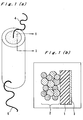
- Figs. 1(a) and 1(b) show one embodiment of a direct methanol fuel cell that embodies the present invention, in which liquid methanol is incorporated into the fuel electrode without passing through a reformer and is used as the fuel.
- Reference numeral 1 designates a tubular membrane made of a perfluorosulfonic acid-type polymer electrolyte, and on an inside of the tube are filled carbon particles 2 loaded with catalyst particles of platinum-ruthenium alloy (e.g. atomic composition, 50:50).
- the cavity of the tube is filled with 1.0-M sulfuric acid and a 3-M methanol solution.
- the inside of the tubular membrane constitutes a fuel electrode.
- platinum particles 3 On the outer side of the tubular membrane, are deposited platinum particles 3, which are fixed thereto, by a chemical plating method, to constitute an air electrode (oxygen electrode), which contacts outside air.
- Reference numerals 4 and 5 designate external terminals connected to the catalyst layers on the inner side and outer side of the tube, respectively, and corresponding to the output terminals of the fuel cell. If there is a need for connecting units of the fuel cell to each other in series, this is achieved by sequentially connecting the terminal 4 of one fuel cell and the terminal 5 of another fuel cell to each other, successively.
- Figs. 2(a) and 2(b) show one embodiment of a structure of a fuel cell suitable for the case where the inside of the tube is filled with gaseous fuel, for example, hydrogen, methanol gas or the like.
- Reference numeral 11 designates a tubular membrane made of a perfluorosulfonic acid-type polymer electrolyte, the inner side of which has a platinum particle layer 12 that is formed by depositing and fixing platinum particles thereon by a chemical plating method, or that is formed by coating thereto carbon particles loaded with platinum catalyst. Hydrogen gas or methanol gas is introduced into the inside of the tube, so that the platinum particle layer 12 serves as a catalyst for the fuel electrode.
- the fuel cell can be made to have the air electrode that is provided on the inner side of the tubular polymer electrolyte membrane, and the fuel electrode that is provided on the outer side of the tubular polymer electrolyte membrane.
- the oxidizer air or oxygen
- the oxidizer is made to pass through inside of the tube to contact with the air electrode, and fuel is fed to the outside of the tube, thereby making the fuel cell operate.
- the entire fuel cell is contained in a vessel filled with the fuel, thereby the fuel electrode provided on the outer side of the tubular membrane is brought into contact with the fuel in the vessel, while keeping the state in which the inside of the tube is sealed not to be contaminated with the fuel.
- the catalysts for fuel electrode and air electrode are preferably platinum family metals such as platinum, rhodium, palladium, ruthenium, and iridium. At least one of these metals is deposited and fixed on the inner side surface and outer side surface of the polymer membrane by a chemical plating method. Also, these catalysts may be fixed by coating or contact bonding the catalyst metal powder onto the membrane surface. Also, a method may be used in which the catalyst metal is dispersed as fine-particulates on the surface of carbon particles and the catalyst-loaded carbon particles are fixed on the inner and outer sides of the tubular membrane. Further, as described above, the catalyst-loaded carbon particles may be filled inside the tubular membrane.
- platinum family metals such as platinum, rhodium, palladium, ruthenium, and iridium. At least one of these metals is deposited and fixed on the inner side surface and outer side surface of the polymer membrane by a chemical plating method. Also, these catalysts may be fixed by coating or contact bonding the catalyst metal powder onto the
- the fuel electrode and air electrode may be provided on any one of the inner and outer sides of the tubular membrane. It is preferred that the fuel electrode is provided on the inner side and the air electrode is provided on the outer side of the membrane.
- the polymer electrolyte membrane material to be used is not necessarily limited to the above-mentioned perfluorosulfonic acid-type polymer, and it may be selected from a perfluorocarbonic acid-type membrane, a poly-styrene-vinylbenzene-type membrane, a quaternary ammonium-type anion-exchange membrane, and the like, as appropriate.
- a membrane made of benzimidazole-based polymer to which phosphoric acid is coordinated and a membrane made of polyacrylic acid impregnated with a concentrated potassium hydroxide solution are also effective, as the electrolyte membrane.
- a membrane made of benzimidazole-based polymer to which phosphoric acid is coordinated and a membrane made of polyacrylic acid impregnated with a concentrated potassium hydroxide solution are also effective, as the electrolyte membrane.
- use of a tubular electrolyte enables construction of fuel cells in which the fuel electrode and oxygen electrode are separated each other and which can be miniaturized (made compact).
- the size (outer/inner diameters), length and film thickness of the tubular polymer electrolyte membrane may be set as appropriate depending on the output power required for the fuel cell, an apparatus to which the fuel cell is applied, or the like.
- the tube has an inner diameter of 0.2 to 10 mm, an outer diameter of 0.5 to 12 mm, and a length of 20 to 1,000 mm.
- it has an inner diameter of 0.3 to 5 mm, an outer diameter of 0.5 to 7 mm, and a length of 30 to 500 mm.
- the fuel is brought into contact with the fuel electrode on the inner or outer side of the tubular polymer electrolyte membrane in a gaseous or liquid state.
- the fuel may be fed continuously or filled in a space on the side of the fuel electrode in advance.
- the oxidizer is brought into contact with the air electrode through the side of the air electrode of the tubular polymer electrolyte membrane. Since the electrolyte is a tubular membrane, the inside of the tube is gas tight and no leakage occurs, so that there is no fear of mixing of the fuel and oxidizer without resort to any special pass (channel), separator, or the like. Further, since the tubular membrane endures the pressure difference across the membrane, control of gas pressure or pressurization can be readily performed.
- the fuel cell of the present invention has high output density and low operating temperature of as low as 100°C so that a long-term durability can be expected. Because of easy handling, the fuel cell of the present invention can be utilized as a power source for mobile phones, video cameras, portable devices such as a note-type personal computer, or a transportable power source.
- the feature of the present invention resides in constructing a fuel cell by use of a tubular (hollow) polymer electrolyte membrane.
- the construction methods shown in Figs. 1(a) and 1(b) and Figs. 2(a) and 2(b) are only examples, and the present invention is not limited thereto with respect to the design of fuel cells, such as selection of catalysts, formation method of catalyst layers, selection of fuels, feeding methods for fuel and air, and the like.
- the fuel cell of the present invention can be applied to small portable devices, it can readily retain its gas tightness of the fuel electrode when constructing the fuel cell, its catalyst loading property is good, it has flexibility in shape upon fabricating a stack, and it is excellent in productivity.
- the fuel cell can be fabricated in a form such that it is adjusted to the contour of the device to which it is applied. Further, a low-temperature operating-type fuel cell that has extremely flexible, easy to make it small and light in weight can be constructed in a simple manner. In addition, for example, when the fuel electrode is formed on the inner side of the tube, injection of fuel is easy, no leakage of fuel occurs, and no cumbersome problem such as selection of sealing material or the like occurs.
- the method of loading catalysts and the area of electrode can be readily changed in design depending on the area where the fuel cell is to be applied.
- the fuel cell as a whole can be made compact (a small fuel cell) and its mass production at low costs is possible.
- a mixed solution of 0.1 M sodium borohydride and 1 M sodium hydroxide was charged inside a tubular Flemion (trade name of a perfluorosulfonic acid-type polymer, produced by Asahi Glass Company, Ltd.) electrolyte membrane having an inner diameter of 0.3 mm, an outer diameter of 0.5 mm and a length of 60 mm, and a 0.1 M aqueous chloroplatinic acid solution was contacted with the outer side of the resultant tube, to form a layer of deposited platinum on the outer side of the tube by a chemical plating method.
- Flemion trade name of a perfluorosulfonic acid-type polymer, produced by Asahi Glass Company, Ltd.
- a mixed solution of 0.1 M sodium borohydride and 1 M sodium hydroxide was charged inside a tubular Flemion electrolyte membrane having an inner diameter of 0.3 mm, an outer diameter of 0.5 mm and a length of 60 mm, and a 0.1 M aqueous chloroplatinic acid solution was contacted with the outer side of the resultant tube, to form a layer of deposited platinum on the outer side of the tube by a chemical plating method. Thereafter, the entire tube was washed with a sulfuric acid solution, and excess unreacted substance was removed, and at the same time the electrolyte membrane was rendered acid-type.
- a syringe a mixture of carbon particles being loaded thereon 20% by mass of platinum and a mixed solution of 3 M potassium hydroxide and 3 M methanol, in a state of suspension.
- the tip of the syringe was used as it was as a connection terminal of the inner catalyst layer serving as the fuel electrode.
- a terminal was connected to the platinum deposit layer formed on the outer side of the tube serving as the air electrode.
Landscapes
- Life Sciences & Earth Sciences (AREA)
- Engineering & Computer Science (AREA)
- Manufacturing & Machinery (AREA)
- Sustainable Development (AREA)
- Sustainable Energy (AREA)
- Chemical & Material Sciences (AREA)
- Chemical Kinetics & Catalysis (AREA)
- Electrochemistry (AREA)
- General Chemical & Material Sciences (AREA)
- Fuel Cell (AREA)
- Inert Electrodes (AREA)
Abstract
Description
Claims (9)
- A fuel cell, comprising a tubular polymer electrolyte membrane, with a fuel electrode on one of inner and outer sides of the membrane, and with an air electrode on the other side of the membrane.
- The fuel cell according to claim 1, wherein said fuel electrode and said air electrode each are composed of a carbon particle material on the surface of which catalyst fine-particulates are dispersed and loaded.
- The fuel cell according to any one of the preceding claims, wherein said tubular polymer electrolyte membrane has a catalyst layer deposited or coated on a surface thereof.
- The fuel cell according to any one of the preceding claims, wherein fuel is brought into contact with said fuel electrode on the surface of said tubular polymer electrolyte membrane, and an oxidizer is brought into contact with said air electrode on the surface of said tubular polymer electrolyte membrane.
- The fuel cell according to any one of the preceding claims, wherein said fuel cell is utilized as a power source of a portable device.
- The fuel cell according to any one of the preceding claims, wherein the fuel electrode is provided on the inner side of the membrane, and the air electrode is provided on the outer side of the membrane.
- The fuel cell according to any one of claims 1 to 5, wherein the fuel electrode is provided on the outer side of the membrane, and the air electrode is provided on the inner side of the membrane.
- The fuel cell according to any one of the preceding claims, which is a small fuel cell.
- The fuel cell according to any one of the preceding claims, wherein the tubular polymer electrolyte membrane has an inner diameter of 0.2 to 10 mm, an outer diameter of 0.5 to 12 mm, and a length of 20 to 1,000 mm.
Applications Claiming Priority (2)
| Application Number | Priority Date | Filing Date | Title |
|---|---|---|---|
| JP2001058277A JP3793801B2 (en) | 2001-03-02 | 2001-03-02 | Small fuel cell |
| JP2001058277 | 2001-03-02 |
Publications (2)
| Publication Number | Publication Date |
|---|---|
| EP1237220A2 true EP1237220A2 (en) | 2002-09-04 |
| EP1237220A3 EP1237220A3 (en) | 2005-06-15 |
Family
ID=18918023
Family Applications (1)
| Application Number | Title | Priority Date | Filing Date |
|---|---|---|---|
| EP02004684A Withdrawn EP1237220A3 (en) | 2001-03-02 | 2002-02-28 | Polymer electrolyte membrane fuel cell |
Country Status (4)
| Country | Link |
|---|---|
| US (1) | US20020122968A1 (en) |
| EP (1) | EP1237220A3 (en) |
| JP (1) | JP3793801B2 (en) |
| CA (1) | CA2373420A1 (en) |
Cited By (2)
| Publication number | Priority date | Publication date | Assignee | Title |
|---|---|---|---|---|
| US7378172B2 (en) * | 2005-05-09 | 2008-05-27 | Atomic Energy Council - Institute Of Nuclear Energy Research | Tubular membrane electrode assembly with leading wire |
| EP1590157A4 (en) * | 2002-12-23 | 2008-06-25 | Microcell Corp | METHOD OF SUBSTRATE FOR MANUFACTURING MICROFIBREUS FUEL CELLS |
Families Citing this family (10)
| Publication number | Priority date | Publication date | Assignee | Title |
|---|---|---|---|---|
| JP3637392B2 (en) * | 2002-04-08 | 2005-04-13 | 独立行政法人産業技術総合研究所 | Fuel cell |
| US6960402B2 (en) * | 2002-06-28 | 2005-11-01 | Advanced Energy Technology Inc. | Perforated cylindrical fuel cells |
| JP4802458B2 (en) | 2004-06-11 | 2011-10-26 | トヨタ自動車株式会社 | Fuel cell |
| JP4440711B2 (en) | 2004-06-11 | 2010-03-24 | トヨタ自動車株式会社 | FUEL CELL CELL MODULE, MANUFACTURING METHOD THEREOF, AND FUEL CELL |
| JP2005353490A (en) * | 2004-06-11 | 2005-12-22 | Toyota Motor Corp | Fuel cell |
| JP2005353484A (en) | 2004-06-11 | 2005-12-22 | Toyota Motor Corp | Membrane electrode composite for tube type fuel cell and current collector for tube type fuel cell |
| JP4945887B2 (en) * | 2004-06-11 | 2012-06-06 | トヨタ自動車株式会社 | Cell module and solid polymer electrolyte fuel cell |
| JP2006216281A (en) * | 2005-02-01 | 2006-08-17 | Toyota Motor Corp | Fuel cell and fuel cell manufacturing method |
| JP4839625B2 (en) * | 2005-02-04 | 2011-12-21 | トヨタ自動車株式会社 | Fuel cell |
| JP2007005162A (en) * | 2005-06-24 | 2007-01-11 | Permelec Electrode Ltd | Method for producing catalyst for fuel cell, gas diffusion electrode using the catalyst, and fuel cell |
Family Cites Families (12)
| Publication number | Priority date | Publication date | Assignee | Title |
|---|---|---|---|---|
| JPS58176876A (en) * | 1982-04-09 | 1983-10-17 | Shin Kobe Electric Mach Co Ltd | Cylindrical type liquid fuel cell |
| JPH06188008A (en) * | 1992-04-01 | 1994-07-08 | Toshiba Corp | Fuel cell |
| JPH07296840A (en) * | 1994-04-27 | 1995-11-10 | Nippon Soken Inc | Polymer electrolyte fuel cell |
| JP3731234B2 (en) * | 1996-02-15 | 2006-01-05 | 松下電器産業株式会社 | Polymer electrolyte fuel cell |
| US6001500A (en) * | 1996-06-05 | 1999-12-14 | Southwest Res Inst | Cylindrical proton exchange membrane fuel cells and methods of making same |
| JPH1064572A (en) * | 1996-08-14 | 1998-03-06 | Matsushita Electric Ind Co Ltd | Fuel supply system for fuel cell and portable electric equipment |
| US6060188A (en) * | 1998-04-06 | 2000-05-09 | Motorola, Inc. | High pressure coaxial fuel cell |
| US6080501A (en) * | 1998-06-29 | 2000-06-27 | Motorola, Inc. | Fuel cell with integral fuel storage |
| JP3427003B2 (en) * | 1999-03-31 | 2003-07-14 | 株式会社東芝 | Fuel cell |
| US20010050234A1 (en) * | 1999-12-22 | 2001-12-13 | Shiepe Jason K. | Electrochemical cell system |
| DE10040282A1 (en) * | 2000-08-14 | 2002-03-07 | Robert Heggemann | fuel cell |
| JP2002158015A (en) * | 2000-11-21 | 2002-05-31 | Sony Corp | Electrochemical element, power generator and power generator |
-
2001
- 2001-03-02 JP JP2001058277A patent/JP3793801B2/en not_active Expired - Lifetime
-
2002
- 2002-02-26 CA CA002373420A patent/CA2373420A1/en not_active Abandoned
- 2002-02-28 EP EP02004684A patent/EP1237220A3/en not_active Withdrawn
- 2002-03-01 US US10/085,052 patent/US20020122968A1/en not_active Abandoned
Cited By (3)
| Publication number | Priority date | Publication date | Assignee | Title |
|---|---|---|---|---|
| EP1590157A4 (en) * | 2002-12-23 | 2008-06-25 | Microcell Corp | METHOD OF SUBSTRATE FOR MANUFACTURING MICROFIBREUS FUEL CELLS |
| US7648665B2 (en) | 2002-12-23 | 2010-01-19 | Microcell Corporation | Substrate-supported process for manufacturing microfibrous fuel cells |
| US7378172B2 (en) * | 2005-05-09 | 2008-05-27 | Atomic Energy Council - Institute Of Nuclear Energy Research | Tubular membrane electrode assembly with leading wire |
Also Published As
| Publication number | Publication date |
|---|---|
| EP1237220A3 (en) | 2005-06-15 |
| JP3793801B2 (en) | 2006-07-05 |
| JP2002260685A (en) | 2002-09-13 |
| US20020122968A1 (en) | 2002-09-05 |
| CA2373420A1 (en) | 2002-09-02 |
Similar Documents
| Publication | Publication Date | Title |
|---|---|---|
| US6972160B2 (en) | Fuel cell | |
| JP4042526B2 (en) | Sheet electrolyte membrane electrode assembly and fuel cell using the same | |
| TW533622B (en) | A fuel cell power generation equipment and a device using the same | |
| US7655335B2 (en) | Air breathing direct methanol fuel cell pack | |
| US6713206B2 (en) | Electrochemical cells comprising laminar flow induced dynamic conducting interfaces, electronic devices comprising such cells, and methods employing same | |
| US6869713B2 (en) | Fuel cell, fuel cell generator, and equipment using the same | |
| JP6219035B2 (en) | Fuel cell and fuel cell composite with asymmetric structure and method thereof | |
| TW531933B (en) | Direct methanol fuel cell system including an integrated methanol sensor and method of fabrication | |
| US20030198853A1 (en) | Air breathing direct methanol fuel cell pack | |
| US20020197520A1 (en) | Micro fuel cell array | |
| US20010049034A1 (en) | Electrochemical cell system | |
| EP1237220A2 (en) | Polymer electrolyte membrane fuel cell | |
| US7374837B2 (en) | Liquid electrochemical cell stacks and manufacturing methods for same | |
| US20080193817A1 (en) | Unit cell for fuel cell, method for manufacturing thereof and fuel cell system | |
| US7378175B2 (en) | Fuel cell and small electric equipment | |
| US20090311576A1 (en) | Direct methanol type fuel cell stack and direct methanol type fuel cell system | |
| EP3893300B1 (en) | Flat tubular solid oxide fuel cell or water electrolysis cell with integrated current collector and manufacturing method of the same | |
| JP2004259705A (en) | Fuel cell, fuel cell power generator and equipment using the same | |
| KR20220170011A (en) | Ultra-thin tube type PEM fuel cell |
Legal Events
| Date | Code | Title | Description |
|---|---|---|---|
| PUAI | Public reference made under article 153(3) epc to a published international application that has entered the european phase |
Free format text: ORIGINAL CODE: 0009012 |
|
| 17P | Request for examination filed |
Effective date: 20020228 |
|
| AK | Designated contracting states |
Kind code of ref document: A2 Designated state(s): AT BE CH CY DE DK ES FI FR GB GR IE IT LI LU MC NL PT SE TR |
|
| AX | Request for extension of the european patent |
Free format text: AL;LT;LV;MK;RO;SI |
|
| RIN1 | Information on inventor provided before grant (corrected) |
Inventor name: YOSHITAKE, MASARU Inventor name: ISHIDA, MASAYOSHI Inventor name: OGURO, KEISUKE Inventor name: ISHIMARU, SHIN-YA Inventor name: OKADA, TATSUHIRO |
|
| PUAL | Search report despatched |
Free format text: ORIGINAL CODE: 0009013 |
|
| AK | Designated contracting states |
Kind code of ref document: A3 Designated state(s): AT BE CH CY DE DK ES FI FR GB GR IE IT LI LU MC NL PT SE TR |
|
| AX | Request for extension of the european patent |
Extension state: AL LT LV MK RO SI |
|
| AKX | Designation fees paid | ||
| STAA | Information on the status of an ep patent application or granted ep patent |
Free format text: STATUS: THE APPLICATION IS DEEMED TO BE WITHDRAWN |
|
| 18D | Application deemed to be withdrawn |
Effective date: 20051228 |
|
| REG | Reference to a national code |
Ref country code: DE Ref legal event code: 8566 |