EP3893300B1 - Flat tubular solid oxide fuel cell or water electrolysis cell with integrated current collector and manufacturing method of the same - Google Patents
Flat tubular solid oxide fuel cell or water electrolysis cell with integrated current collector and manufacturing method of the same Download PDFInfo
- Publication number
- EP3893300B1 EP3893300B1 EP20168381.0A EP20168381A EP3893300B1 EP 3893300 B1 EP3893300 B1 EP 3893300B1 EP 20168381 A EP20168381 A EP 20168381A EP 3893300 B1 EP3893300 B1 EP 3893300B1
- Authority
- EP
- European Patent Office
- Prior art keywords
- current collector
- unit
- solid oxide
- fuel cell
- oxide fuel
- Prior art date
- Legal status (The legal status is an assumption and is not a legal conclusion. Google has not performed a legal analysis and makes no representation as to the accuracy of the status listed.)
- Active
Links
- 239000000446 fuel Substances 0.000 title claims description 127
- 239000007787 solid Substances 0.000 title claims description 80
- 238000004519 manufacturing process Methods 0.000 title claims description 35
- XLYOFNOQVPJJNP-UHFFFAOYSA-N water Substances O XLYOFNOQVPJJNP-UHFFFAOYSA-N 0.000 title description 8
- 238000005868 electrolysis reaction Methods 0.000 title description 7
- 238000007789 sealing Methods 0.000 claims description 66
- 238000000034 method Methods 0.000 claims description 20
- 239000003792 electrolyte Substances 0.000 claims description 19
- 230000008569 process Effects 0.000 claims description 18
- 238000010168 coupling process Methods 0.000 claims description 17
- 230000008878 coupling Effects 0.000 claims description 14
- 238000005859 coupling reaction Methods 0.000 claims description 14
- 239000002737 fuel gas Substances 0.000 claims description 7
- 238000007650 screen-printing Methods 0.000 claims description 6
- 239000007789 gas Substances 0.000 description 19
- 239000001301 oxygen Substances 0.000 description 12
- 229910052760 oxygen Inorganic materials 0.000 description 12
- 230000008901 benefit Effects 0.000 description 9
- 239000000945 filler Substances 0.000 description 9
- 239000000565 sealant Substances 0.000 description 8
- QVGXLLKOCUKJST-UHFFFAOYSA-N atomic oxygen Chemical compound [O] QVGXLLKOCUKJST-UHFFFAOYSA-N 0.000 description 6
- 230000005611 electricity Effects 0.000 description 6
- 239000006262 metallic foam Substances 0.000 description 6
- -1 oxygen ions Chemical class 0.000 description 6
- 238000003487 electrochemical reaction Methods 0.000 description 5
- 238000010030 laminating Methods 0.000 description 5
- 238000003475 lamination Methods 0.000 description 5
- UFHFLCQGNIYNRP-UHFFFAOYSA-N Hydrogen Chemical compound [H][H] UFHFLCQGNIYNRP-UHFFFAOYSA-N 0.000 description 4
- 230000006835 compression Effects 0.000 description 4
- 238000007906 compression Methods 0.000 description 4
- OKKJLVBELUTLKV-UHFFFAOYSA-N Methanol Chemical compound OC OKKJLVBELUTLKV-UHFFFAOYSA-N 0.000 description 3
- 239000001257 hydrogen Substances 0.000 description 3
- 229910052739 hydrogen Inorganic materials 0.000 description 3
- 239000000463 material Substances 0.000 description 3
- MYMOFIZGZYHOMD-UHFFFAOYSA-N Dioxygen Chemical compound O=O MYMOFIZGZYHOMD-UHFFFAOYSA-N 0.000 description 2
- 239000000853 adhesive Substances 0.000 description 2
- 230000001070 adhesive effect Effects 0.000 description 2
- 239000003054 catalyst Substances 0.000 description 2
- 230000007797 corrosion Effects 0.000 description 2
- 238000005260 corrosion Methods 0.000 description 2
- 230000001419 dependent effect Effects 0.000 description 2
- 229910001882 dioxygen Inorganic materials 0.000 description 2
- 238000005516 engineering process Methods 0.000 description 2
- 238000001125 extrusion Methods 0.000 description 2
- 239000011521 glass Substances 0.000 description 2
- GPRLSGONYQIRFK-UHFFFAOYSA-N hydron Chemical compound [H+] GPRLSGONYQIRFK-UHFFFAOYSA-N 0.000 description 2
- VNWKTOKETHGBQD-UHFFFAOYSA-N methane Chemical compound C VNWKTOKETHGBQD-UHFFFAOYSA-N 0.000 description 2
- 239000010970 precious metal Substances 0.000 description 2
- 238000002407 reforming Methods 0.000 description 2
- 230000035939 shock Effects 0.000 description 2
- 125000006850 spacer group Chemical group 0.000 description 2
- 230000008646 thermal stress Effects 0.000 description 2
- 229910001233 yttria-stabilized zirconia Inorganic materials 0.000 description 2
- 239000004215 Carbon black (E152) Substances 0.000 description 1
- BVKZGUZCCUSVTD-UHFFFAOYSA-L Carbonate Chemical compound [O-]C([O-])=O BVKZGUZCCUSVTD-UHFFFAOYSA-L 0.000 description 1
- 229910019142 PO4 Inorganic materials 0.000 description 1
- BQCADISMDOOEFD-UHFFFAOYSA-N Silver Chemical compound [Ag] BQCADISMDOOEFD-UHFFFAOYSA-N 0.000 description 1
- 239000003513 alkali Substances 0.000 description 1
- 239000003034 coal gas Substances 0.000 description 1
- 238000000576 coating method Methods 0.000 description 1
- 238000009826 distribution Methods 0.000 description 1
- 230000020169 heat generation Effects 0.000 description 1
- 229930195733 hydrocarbon Natural products 0.000 description 1
- 150000002430 hydrocarbons Chemical class 0.000 description 1
- 238000002844 melting Methods 0.000 description 1
- 230000008018 melting Effects 0.000 description 1
- 239000007769 metal material Substances 0.000 description 1
- 238000012986 modification Methods 0.000 description 1
- 230000004048 modification Effects 0.000 description 1
- 239000003345 natural gas Substances 0.000 description 1
- 239000007800 oxidant agent Substances 0.000 description 1
- 230000001590 oxidative effect Effects 0.000 description 1
- NBIIXXVUZAFLBC-UHFFFAOYSA-K phosphate Chemical compound [O-]P([O-])([O-])=O NBIIXXVUZAFLBC-UHFFFAOYSA-K 0.000 description 1
- 239000010452 phosphate Substances 0.000 description 1
- 229920000642 polymer Polymers 0.000 description 1
- 238000010248 power generation Methods 0.000 description 1
- 239000003566 sealing material Substances 0.000 description 1
- 238000004904 shortening Methods 0.000 description 1
- 229910052709 silver Inorganic materials 0.000 description 1
- 239000004332 silver Substances 0.000 description 1
Images

Classifications
-
- H—ELECTRICITY
- H01—ELECTRIC ELEMENTS
- H01M—PROCESSES OR MEANS, e.g. BATTERIES, FOR THE DIRECT CONVERSION OF CHEMICAL ENERGY INTO ELECTRICAL ENERGY
- H01M8/00—Fuel cells; Manufacture thereof
- H01M8/02—Details
- H01M8/0202—Collectors; Separators, e.g. bipolar separators; Interconnectors
-
- H—ELECTRICITY
- H01—ELECTRIC ELEMENTS
- H01M—PROCESSES OR MEANS, e.g. BATTERIES, FOR THE DIRECT CONVERSION OF CHEMICAL ENERGY INTO ELECTRICAL ENERGY
- H01M8/00—Fuel cells; Manufacture thereof
- H01M8/02—Details
- H01M8/0271—Sealing or supporting means around electrodes, matrices or membranes
-
- H—ELECTRICITY
- H01—ELECTRIC ELEMENTS
- H01M—PROCESSES OR MEANS, e.g. BATTERIES, FOR THE DIRECT CONVERSION OF CHEMICAL ENERGY INTO ELECTRICAL ENERGY
- H01M8/00—Fuel cells; Manufacture thereof
- H01M8/10—Fuel cells with solid electrolytes
- H01M8/12—Fuel cells with solid electrolytes operating at high temperature, e.g. with stabilised ZrO2 electrolyte
- H01M2008/1293—Fuel cells with solid oxide electrolytes
-
- H—ELECTRICITY
- H01—ELECTRIC ELEMENTS
- H01M—PROCESSES OR MEANS, e.g. BATTERIES, FOR THE DIRECT CONVERSION OF CHEMICAL ENERGY INTO ELECTRICAL ENERGY
- H01M8/00—Fuel cells; Manufacture thereof
- H01M8/02—Details
- H01M8/0271—Sealing or supporting means around electrodes, matrices or membranes
- H01M8/0286—Processes for forming seals
-
- H—ELECTRICITY
- H01—ELECTRIC ELEMENTS
- H01M—PROCESSES OR MEANS, e.g. BATTERIES, FOR THE DIRECT CONVERSION OF CHEMICAL ENERGY INTO ELECTRICAL ENERGY
- H01M8/00—Fuel cells; Manufacture thereof
- H01M8/24—Grouping of fuel cells, e.g. stacking of fuel cells
- H01M8/241—Grouping of fuel cells, e.g. stacking of fuel cells with solid or matrix-supported electrolytes
- H01M8/2425—High-temperature cells with solid electrolytes
- H01M8/243—Grouping of unit cells of tubular or cylindrical configuration
-
- Y—GENERAL TAGGING OF NEW TECHNOLOGICAL DEVELOPMENTS; GENERAL TAGGING OF CROSS-SECTIONAL TECHNOLOGIES SPANNING OVER SEVERAL SECTIONS OF THE IPC; TECHNICAL SUBJECTS COVERED BY FORMER USPC CROSS-REFERENCE ART COLLECTIONS [XRACs] AND DIGESTS
- Y02—TECHNOLOGIES OR APPLICATIONS FOR MITIGATION OR ADAPTATION AGAINST CLIMATE CHANGE
- Y02E—REDUCTION OF GREENHOUSE GAS [GHG] EMISSIONS, RELATED TO ENERGY GENERATION, TRANSMISSION OR DISTRIBUTION
- Y02E60/00—Enabling technologies; Technologies with a potential or indirect contribution to GHG emissions mitigation
- Y02E60/30—Hydrogen technology
- Y02E60/50—Fuel cells
-
- Y—GENERAL TAGGING OF NEW TECHNOLOGICAL DEVELOPMENTS; GENERAL TAGGING OF CROSS-SECTIONAL TECHNOLOGIES SPANNING OVER SEVERAL SECTIONS OF THE IPC; TECHNICAL SUBJECTS COVERED BY FORMER USPC CROSS-REFERENCE ART COLLECTIONS [XRACs] AND DIGESTS
- Y02—TECHNOLOGIES OR APPLICATIONS FOR MITIGATION OR ADAPTATION AGAINST CLIMATE CHANGE
- Y02P—CLIMATE CHANGE MITIGATION TECHNOLOGIES IN THE PRODUCTION OR PROCESSING OF GOODS
- Y02P70/00—Climate change mitigation technologies in the production process for final industrial or consumer products
- Y02P70/50—Manufacturing or production processes characterised by the final manufactured product
Definitions
- the present disclosure relates to a solid oxide fuel cell or water electrolysis cell, and more particularly, to a solid oxide fuel cell or water electrolysis cell using an integrated current collector and a manufacturing method of the same.
- a solid oxide fuel cell is a fuel cell which uses solid oxide with oxygen or hydrogen ion conductivity as electrolytes and operates at the highest temperature (600 to 1000°C) among existing fuel cells. Further, all components are made of solid so that the structure of the solid oxide fuel cell is simpler than the other fuel cells. Further, the solid oxide fuel cell does not have electrolyte loss, replenishment, corrosion problems and does not need a precious metal catalyst so that the fuel may be directly supplied therein through internal reforming. The solid oxide fuel cell reversely performs an electrochemical reaction to be used as a high temperature hydroelectrolyzer (solid oxide electrolyzer cell: SOEC).
- SOEC solid oxide electrolyzer cell
- the electrochemical reactors such as a solid oxide fuel cell and a high temperature hydroelectrolyzer are mainly classified into a flat type and a cylindrical type depending on the shape.
- the flat type has an advantage of a high power density (output), but also has disadvantages in that a gas sealing area is large, a thermal shock is caused by a difference in thermal expansion coefficients between materials during the lamination, and it is not easy to increase a size.
- the cylindrical type has advantages in that the resistance against the thermal stress and the mechanical strength are relatively high and it is possible to increase the size using extrusion molding, but also has a limitation in that the power density (output) is low.
- a flat tubular electrochemical reactor (a flat tubular solid oxide fuel cell) which introduces the advantages of the flat type and cylindrical type electrochemical reactors may implement a desired output performance by laminating a plurality of unit cells (single cells or unit cells) to increase a power density.
- US 2016/372778 A1 discloses a flat-plate-type fuel cell stack including a plurality of plate-shaped stacked fuel cells each including an electrolyte layer, an anode, and a cathode.
- the fuel cell stack includes at least one of a fuel manifold communicating with a space adjacent to the anode and an oxidant manifold communicating with a space adjacent to the cathode.
- a compression seal member and a glass seal member are disposed around the at least one manifold.
- a solid oxide fuel cell stack having a compression plate and a terminal fuel cell includes a current collector plate comprising a substantially solid planar element disposed immediately adjacent the compression plate; an gas-impermeable interconnect plate disposed immediately adjacent and in electrical contact with the terminal fuel cell; and a compressible electrically conductive element in electrical contact with the interconnect plate and the current collector plate.
- An object of the present disclosure is to provide a solid oxide fuel cell or water electrolysis cell using an integrated current collector which prevents wobbling and slipping phenomenon caused by a load due to the stack lamination, by laminating cell stacks of s solid oxide fuel cell with a current collector in which a filler equipped in a sealing unit is integrally formed.
- Another object of the present disclosure is to provide a solid oxide fuel cell or water electrolysis cell using an integrated current collector which increases a convenience for manufacturing a cell stack and a structural stability by shortening a coupling process of a sealing unit.
- a solid oxide fuel cell using an integrated current collector includes at least one unit cell including a fuel electrode, an electrolyte film, and an air electrode; a first current collector and a second current collector which are provided on both surfaces of the at least one unit cell and have a filling unit integrally formed at both ends of a body; and a sealing unit formed on both surfaces of the filling unit.
- the solid oxide fuel cell using an integrated current collector may further include: a first housing formed on the other surface of the first current collector and a second housing formed on one surface of the second current collector to support the at least one unit cell.
- the filling unit and the sealing unit include a hole formed to penetrate in a thickness direction to move fuel gas flowing to the at least one unit cell therethrough, and a hole equipped in the filling unit and a hole equipped in the sealing unit may communicate with each other.
- the sealing unit may be formed on both surfaces of the filling unit using one of a bonding process, a screen printing process, and a dispenser process.
- the solid oxide fuel cell is a flat tubular type.
- a manufacturing method of a solid oxide fuel cell using an integrated current collector is a manufacturing method of a solid oxide fuel cell including at least one unit cell in which a fuel electrode, an electrolyte film, and an air electrode are laminated. The method includes: preparing a first current collector and a second current collector in which a filling unit is integrally formed at both ends of a body; coupling a sealing unit onto both surfaces of the filling unit; and coupling the first current collector and the second current collector onto both surfaces of the at least one unit cell to manufacture the solid oxide fuel cell.
- the manufacturing method of a solid oxide fuel cell using an integrated current collector may further include: coupling a first housing onto the other surface of the first current collector and coupling a second housing onto one surface of the second current collector to support the at least one unit cell.
- one of a bonding process, a screen printing process, and a dispenser process may be used.
- a solid oxide water electrolysis cell using an integrated current collector includes at least one unit cell including a hydrogen electrode, an electrolyte film, and an air electrode, a first current collector and a second current collector which are provided on both surfaces of the at least one unit cell and have a filling unit integrally formed at both ends of a body, and a sealing unit formed on both surfaces of the filling unit.
- the cell stack of the solid oxide fuel cell is laminated by implementing a current collector in which a filler equipped in a sealing unit is integrally formed, to prevent wobbling and slipping phenomenon caused by a load due to the stack lamination.
- the coupling process of the sealing unit is shortened to enhance the convenience for manufacturing the cell stack and the structural stability.
- a fuel cell is a high efficiency clean power generation technology which directly converts hydrogen contained in a hydrocarbon-based material such as natural gas, coal gas, and methanol and oxygen in the air into electrical energy by electrochemical reaction and is largely classified into an alkali type, a phosphate type, a molten carbonate, a solid oxide, and polymer fuel cells depending on a type of used electrolyte.
- a solid oxide fuel cell is a fuel cell which uses solid oxide with oxygen or hydrogen ion conductivity as electrolytes and operates at the highest temperature (600 to 1000°C) among existing fuel cells. Further, all components are made of solid so that the structure of the solid oxide fuel cell is simpler than the other fuel cells. Further, the solid oxide fuel cell does not have electrolyte loss, replenishment, corrosion problems and does not need precious metal catalyst so that the fuel may be directly supplied therein through internal reforming. The solid oxide fuel cell reversely performs an electrochemical reaction to be used as a high temperature solid oxide electrolyzer cell (SOEC).
- SOEC solid oxide electrolyzer cell
- the electrochemical reactors such as a solid oxide fuel cell and a high temperature hydroelectrolyzer are mainly classified into a flat type and a cylindrical type depending on the shape.
- the flat type has an advantage of a high power density (output), but also has disadvantages in that a gas sealing area is large, a thermal shock is caused by a difference in thermal expansion coefficients between materials during the lamination, and it is not easy to increase a size.
- the cylindrical type has advantages in that the resistance against the thermal stress and the mechanical strength are relatively high and it is possible to increase the size using extrusion molding, but also has a limitation in that the power density (output) is low.
- a flat tubular electrochemical reactor (a flat tubular solid oxide fuel cell) which introduces the advantages of the flat type and cylindrical type electrochemical reactors may implement a desired output performance by laminating a plurality of unit cells (single cells or unit cells) to increase a power density.
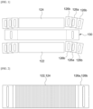
- a flat tubular fuel cell of the related art implements a cell stack by bonding separate current collectors 122 and 124 and sealants 126b to unit cells 130 to achieve the electrical contact between unit cells and sealing of the fuel gas between a fuel electrode and an air electrode.
- a filler 126a is used to fill the height difference to prevent the deformation of the sealant 126b due to the temperature rise in accordance with the operation of the fuel cell.
- parts of the current collectors 122 and 124 are implemented as a filler 126a to prevent the wobbling and slipping phenomenon which may be caused after melting the sealant 126b. That is, the current collector and the filler which have been separately used in the related art are integrally manufactured.
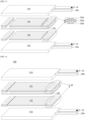
- FIG. 3 is an exploded perspective view illustrating a solid oxide fuel cell equipped with a separable current collector used in the related art
- FIG. 4 is an exploded perspective view illustrating a solid oxide fuel cell with an integrated current collector according to an exemplary embodiment of the present disclosure
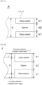
- FIGS. 5A to 5C are cross-sectional views illustrating structures of a filling unit and a sealing unit formed at both ends of an integrated current collector, according to an exemplary embodiment of the present disclosure.
- a solid oxide fuel cell equipped with a separable current collector used in the related art includes at least one unit cell 130, current collectors 122 and 124, a sealing unit 126b, a gas inlet 20a, a gas outlet 20b, and housings 112 and 124.
- the flat tubular solid oxide fuel cell is classified into two types: an air electrode support type fuel cell which uses an air electrode (a cathode) as a support of the fuel cell and a fuel electrode support type fuel cell which uses a fuel electrode (an anode) as a support. Between the air electrode support type fuel cell and the fuel electrode support type fuel cell, the fuel electrode support type is an advanced type so that the current solid oxide fuel cell is being studied and developed with respect to the fuel electrode support type.
- At least one unit cell 130 may be configured by sequentially laminating a fuel electrode, an electrolyte film, and an air electrode from an inside (or a lower side).
- the electrolyte film serves as a moving passage of oxygen ions formed in the air electrode and block the direct contact between air and the fuel and block the movement of the electrons.
- the fuel electrode serves to send electrons generated when the oxygen ion transmitted through the electrolyte film and the fuel cause electrochemical reaction, to the outside.
- the fuel electrode is supplied with oxygen or oxygen gas in the air and the electron supplied from the fuel electrode is combined with the oxygen to form an oxygen ion.
- the oxygen ion moves through the electrolyte film to reach the fuel electrode, the oxygen ion reacts with hydrogen gas which is a fuel to generate water and discharge electrons.
- hydrogen gas which is a fuel to generate water and discharge electrons.
- the electrons generated in the fuel electrode flow to the external circuit to generate current to generate electricity.
- holes which are formed to penetrate in a thickness direction are formed at both ends of the unit cell 130 to introduce and discharge the fuel gas.
- the current collectors 122 and 124 include terminals which collect electricity to collect electricity formed in at least one unit cell 130.
- the current collectors 122 and 124 may include a first current collector 122 located on a lowermost portion of at least one unit cell 130 and a second current collector 124 located on an uppermost portion of at least one unit cell 130.
- the first current collector 122 may be a fuel electrode layer current collector and the second current collector 124 may be an air electrode layer current collector.
- first current collector 122 and the second current collector 124 may be coupled onto both surfaces of the unit cell 130.
- the first current collector 122 is coupled to a lower portion of the lowermost unit cell 130 and the second current collector 124 is coupled to an upper portion of the uppermost unit cell 130.
- the sealing units 126b are formed on both ends of the unit cell 130 and is provided in a position spaced apart from the current collectors 122 and 124 with a predetermined interval. That is, the sealing units 126b may be formed on upper portion and lower portion of both ends of the unit cell 130 and may be equipped in the unit cell 130 to be separated from the current collectors 122 and 124.
- the sealing unit 126b may include a filling unit 126a to fill the height difference to prevent the deformation of the sealant due to the temperature rise in accordance with the operation of the fuel cell.
- the sealing unit 126b may be implemented such that sealing members are coupled onto both surfaces of the filling unit 126a.
- a glass sealant may be used, and, as the filling unit 126a, crofer or yttria stabilized zirconia (YSZ) may be used.
- the housings 112 and 114 are frames used to support at least one unit cell 130 and may be formed at the outside of the current collectors 122 and 124.
- the housings 112 and 114 includes a first housing 112 coupled to the other surface, that is, a lower portion of the first current collector 122 and a second housing 114 which is coupled to one surface, that is, an upper portion of the second current collector 124.
- the housings 112 and 114 are desirably implemented by a metal material which minimizes deformation at a high temperature.
- a gas inlet which introduces fuel gas flowing to the unit cell 130 and a gas outlet which discharges the fuel gas.
- the gas inlet may be connected to the first housing 112 and the gas outlet may be connected to the second housing 114 and the positions of the gas inlet and the gas outlet may be changed in accordance with a laminating order of the fuel electrode, the electrolyte film, and the air electrode of the unit cell 130.
- first housing 112 and the second housing 114 may further include an electric terminal 10 connected to the outside.
- the solid oxide fuel cell of the related art with the above-described structure is configured by the current collectors 122 and 124 and the sealing unit 126b which are separately formed so that the following problems may occur.
- a solid oxide fuel cell 100 with an integrated current collector includes at least one unit cell 130, current collectors 122 and 124, a sealing unit 126b, a gas inlet, a gas outlet, and a housing.
- the at least one unit cell 130, the gas inlet, the gas outlet, and the housing of the solid oxide fuel cell 100 performs the same functions as the at least one unit cell 130, the gas inlet 20a, the gas outlet 20b, and the housings 112 and 114 of the solid oxide fuel cell of the related art so that only the current collectors 122 and 124 and the sealing unit 126b will be described below.
- the current collectors 122 and 124 include terminals which collect electricity to collect electricity formed in at least one unit cell 130.
- the current collectors 122 and 124 may include a first current collector 122 located on a lowermost portion of at least one unit cell 130 and a second current collector 124 located on an uppermost portion of at least one unit cell 130.
- the first current collector 122 may be a fuel electrode layer current collector and the second current collector 124 may be an air electrode layer current collector.
- first current collector 122 and the second current collector 124 may be coupled to both surfaces of the unit cell 130.
- the first current collector 122 is coupled to a lower portion of the lowermost unit cell 130 and the second current collector 124 is coupled to an upper portion of the uppermost unit cell 130.
- filling units 126a may be integrally formed with both ends of the bodies.
- the current collector 122 and 124 of the related art may implement both ends of the body as filling units 126a.
- the sealing units 126b may be formed on both surfaces of the filling unit 126a. In other words, the sealing units 126b may be formed to be coupled onto both surfaces of the filling unit 126a.
- the filling unit 126a and the sealing unit 126b may include holes which are formed to penetrate in a thickness direction to move a fuel gas flowing to the at least one unit cell 130 therethrough.
- the hole equipped in the filling unit 126a and the hole equipped in the sealing unit 126b may communicate with each other.
- a thickness h of the current collectors 122 and 124 may satisfy the following Equation 1 with regard to a thickness h1 of the sealing unit 126b and a thickness h2 of the filling unit 126a.
- Thickness h of first current collector 122 or second current collector 124 Thickness h 2 of filling unit 126 a + Thickness h 1 of sealing unit 126 b ⁇ 2
- the thickness of the first current collector 122 or the second current collector 124 may be desirably equal to a thickness obtained by adding all a thickness of the sealing unit 126b formed on a top surface of the filling unit 126a, a thickness of the sealing unit 126b formed on a bottom surface of the filling unit 126a and a thickness of the filling unit 126a.
- FIGS. 5A and 5B are examples formed with an A-type current collector structure.
- the A-type current collector is formed such that the first current collector and the second current collector and the filling unit (spacer) are integrally formed as a current collector, and the filling unit which is integrally formed with the first current collector or the second current collector is not a rectangular shape.
- the integrated current collector may be formed to include only a filler area in which the sealing unit 126b is formed or as illustrated in FIG. 5B , the integrated current collector may be formed such that a filler area in which the sealing unit 126b is formed and a filler area in which a metallic foam is formed are divided.
- FIG. 5C illustrates a B-type current collector, and the B-type current collector is formed such that the first current collector and the second current collector and a filling unit (spacer) are integrally formed as a current collector, and the integrated current collector has a rectangular shape.
- the thickness of the sealing unit 126b is the same as the thickness of the metallic foam.
- the metallic foam has a high conductivity and sufficient porosity and even though the thickness changes due to the compression of the sealing material, the conduction and gas permeation may be easily performed.
- the metallic foam may be formed by silver (Ag) metallic foam.
- the thickness h of the first collector 122 or the second current collector 124 may be a value obtained by adding the thickness h2 of the filling unit 126a and twice the thickness h1 of the sealing unit 126b, and the thickness of the metallic foam may be larger or smaller than h1 depending on whether the current collector is the A type or B type.
- the thickness of the current collectors 122 and 124 is uniformly formed in a center portion and both ends so that the unit cell 130 may be more stably supported. Further, the wobbling and slipping phenomenon which may be generated when the plurality of unit cells 130 is laminated may be prevented.
- the sealing unit 126b may be formed on both surfaces of the filling unit 126a by performing a screen printing process using a sticker type or adhesive type sealing member.
- sealing unit 126b may be formed on both surfaces of the filling unit 126a by performing a dispenser process of squeezing an elastic sealing member injected into a syringe or a tube.
- sealing unit 126b may be formed on both surfaces of the filling unit 126a by performing a coating process using a roll or a transfer plate.
- sealing unit 126b may be formed on both surfaces of the filling unit 126a by performing a bonding process using an adhesive.
- the coupling process of the sealing unit 126b is shortened to enhance the convenience for manufacturing the cell stack and the structural stability.
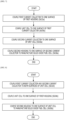
- FIG. 6 is a flowchart illustrating a manufacturing method of a solid oxide fuel cell using an integrated current collector according to an exemplary embodiment of the present disclosure
- FIGS. 7 and 8 are flowcharts illustrating a manufacturing method of a solid oxide fuel cell of FIG. 6 in detail.
- a manufacturing apparatus of a solid oxide fuel cell using an integrated current collector may prepare a first current collector 122 and a second current collector 124 with a filling unit 126a integrally formed at both ends of a body.
- At least one unit cell 130 in which a fuel electrode, an electrolyte film and an air electrode are laminated may be further prepared to be coupled with the first current collector 122 and the second current collector 124.
- the first current collector 122 and the second current collector 124 are devices which collect electricity formed in at least one unit cell 130 and include the filling unit 126a integrally formed at both ends of the body.
- step S620 the manufacturing apparatus of a solid oxide fuel cell using an integrated current collector according to the exemplary embodiment of the present disclosure couples the sealing unit 126b onto both surfaces of the filling unit 126a.
- the sealing unit 126b may be coupled onto both surfaces of the filling unit 126a using one of a bonding process, a screen printing process, and a dispenser process.
- the thickness of the first current collector 122 or the second current collector 124 may be desirably equal to a thickness obtained by adding a thickness of the sealing unit 126b formed on a top surface of the filling unit 126a and a thickness of the sealing unit 126b formed on a bottom surface of the filling unit 126a and a thickness of the filling unit 126a.
- the manufacturing apparatus of a solid oxide fuel cell using an integrated current collector may manufacture the solid oxide fuel cell by coupling the first current collector 122 and the second current collector 124 onto both surfaces of at least one unit cell 130.
- a step of coupling a first housing 112 to the other surface of the first current collector 122 and coupling a second housing 114 to one surface of the second current collector 124 may be further included.
- the housings 112 and 114 are frames used to support at least one unit cell 130 and the first housing 112 is coupled to the other surface, that is, a lower portion of the first current collector and the second housing 114 is coupled to one surface, that is, an upper portion of the second current collector 124.
- Step S630 will be described in more detail below by reflecting the step of coupling the first housing 112 and the second housing 114.
- the manufacturing apparatus of a solid oxide fuel cell using an integrated current collector may couple the first current collector 122 onto one surface of the first housing 112, that is, a top surface.
- the manufacturing apparatus of a solid oxide fuel cell using an integrated current collector may couple the unit cell 130 onto one surface of the first current collector 122, that is, a top surface.
- step S636a the manufacturing apparatus of a solid oxide fuel cell using an integrated current collector according to the exemplary embodiment of the present disclosure may couple the second current collector 124 onto one surface of the unit cell 130.
- step S638a the manufacturing apparatus of a solid oxide fuel cell using an integrated current collector according to the exemplary embodiment of the present disclosure may couple the second housing 114 onto one surface of the second current collector 124 to manufacture a solid oxide fuel cell.
- the first current collector 122, the unit cell 130, and the second current collector 124 are sequentially coupled between the first housing 112 and the second housing 114 to manufacture a solid oxide fuel cell.
- the manufacturing apparatus of a solid oxide fuel cell using an integrated current collector may couple the first current collector 122 and the second current collector 124 onto both surfaces of the unit cell 130.
- the manufacturing apparatus of a solid oxide fuel cell using an integrated current collector may couple the unit cell 130 onto one surface of the first housing 112, that is, a top surface.
- step S636b the manufacturing apparatus of a solid oxide fuel cell using an integrated current collector according to the exemplary embodiment of the present disclosure may couple the second housing 114 onto one surface of the unit cell 130 to manufacture a solid oxide fuel cell.
- the first current collector 122 and the second current collector 124 are coupled onto both surfaces of the unit cell 130 first, and then coupled between the first housing 112 and the second housing 114.
- the fuel electrode of the at least one unit cell is constituted into a hydrogen electrode, and other configurations and function are equally applied to the solid oxide water electrolysis cell. Namely, the solid oxide fuel cell reversely performs an electrochemical reaction to be used as a solid oxide electrolyzer cell (SOEC).
- SOEC solid oxide electrolyzer cell
Landscapes
- Life Sciences & Earth Sciences (AREA)
- Engineering & Computer Science (AREA)
- Manufacturing & Machinery (AREA)
- Sustainable Development (AREA)
- Sustainable Energy (AREA)
- Chemical & Material Sciences (AREA)
- Chemical Kinetics & Catalysis (AREA)
- Electrochemistry (AREA)
- General Chemical & Material Sciences (AREA)
- Fuel Cell (AREA)
Description
- The present disclosure relates to a solid oxide fuel cell or water electrolysis cell, and more particularly, to a solid oxide fuel cell or water electrolysis cell using an integrated current collector and a manufacturing method of the same.
- A solid oxide fuel cell (SOFC) is a fuel cell which uses solid oxide with oxygen or hydrogen ion conductivity as electrolytes and operates at the highest temperature (600 to 1000°C) among existing fuel cells. Further, all components are made of solid so that the structure of the solid oxide fuel cell is simpler than the other fuel cells. Further, the solid oxide fuel cell does not have electrolyte loss, replenishment, corrosion problems and does not need a precious metal catalyst so that the fuel may be directly supplied therein through internal reforming. The solid oxide fuel cell reversely performs an electrochemical reaction to be used as a high temperature hydroelectrolyzer (solid oxide electrolyzer cell: SOEC).
- The electrochemical reactors such as a solid oxide fuel cell and a high temperature hydroelectrolyzer are mainly classified into a flat type and a cylindrical type depending on the shape. The flat type has an advantage of a high power density (output), but also has disadvantages in that a gas sealing area is large, a thermal shock is caused by a difference in thermal expansion coefficients between materials during the lamination, and it is not easy to increase a size. Further, the cylindrical type has advantages in that the resistance against the thermal stress and the mechanical strength are relatively high and it is possible to increase the size using extrusion molding, but also has a limitation in that the power density (output) is low.
- A flat tubular electrochemical reactor (a flat tubular solid oxide fuel cell) which introduces the advantages of the flat type and cylindrical type electrochemical reactors may implement a desired output performance by laminating a plurality of unit cells (single cells or unit cells) to increase a power density.
- However, due to the load distribution problem caused in accordance with the lamination of the plurality of cells, a slippage of the sealant formed in a portion where a cell stack is sealed may occur, so that gas leakage and heat generation are generated to collapse the stack stability, which degrades the performance of the cell.
- Accordingly, there is a need for development of a technology for performing electrical contact between unit cells and gas sealing between a fuel electrode and an air electrode.
-
Korean Registered Patent Publication No. 10-1503458 (Published on March 11, 2015 -
US 2016/372778 A1 discloses a flat-plate-type fuel cell stack including a plurality of plate-shaped stacked fuel cells each including an electrolyte layer, an anode, and a cathode. The fuel cell stack includes at least one of a fuel manifold communicating with a space adjacent to the anode and an oxidant manifold communicating with a space adjacent to the cathode. A compression seal member and a glass seal member are disposed around the at least one manifold. -
US 2004/1 85321 A1 discloses that a solid oxide fuel cell stack having a compression plate and a terminal fuel cell includes a current collector plate comprising a substantially solid planar element disposed immediately adjacent the compression plate; an gas-impermeable interconnect plate disposed immediately adjacent and in electrical contact with the terminal fuel cell; and a compressible electrically conductive element in electrical contact with the interconnect plate and the current collector plate. - An object of the present disclosure is to provide a solid oxide fuel cell or water electrolysis cell using an integrated current collector which prevents wobbling and slipping phenomenon caused by a load due to the stack lamination, by laminating cell stacks of s solid oxide fuel cell with a current collector in which a filler equipped in a sealing unit is integrally formed.
- Further, another object of the present disclosure is to provide a solid oxide fuel cell or water electrolysis cell using an integrated current collector which increases a convenience for manufacturing a cell stack and a structural stability by shortening a coupling process of a sealing unit.
- Technical problems of the present disclosure are not limited to the above-mentioned technical problem(s), and other technical problem(s), which is (are) not mentioned above, can be clearly understood by those skilled in the art from the following descriptions.
- A solid oxide fuel cell using an integrated current collector according to claim 1 is provided. Further embodiments are described in the dependent claims. A solid oxide fuel cell using an integrated current collector includes at least one unit cell including a fuel electrode, an electrolyte film, and an air electrode; a first current collector and a second current collector which are provided on both surfaces of the at least one unit cell and have a filling unit integrally formed at both ends of a body; and a sealing unit formed on both surfaces of the filling unit.
- Further, the solid oxide fuel cell using an integrated current collector according to an exemplary embodiment of the present disclosure may further include: a first housing formed on the other surface of the first current collector and a second housing formed on one surface of the second current collector to support the at least one unit cell.
- Further, according to one exemplary embodiment of the present disclosure, the filling unit and the sealing unit include a hole formed to penetrate in a thickness direction to move fuel gas flowing to the at least one unit cell therethrough, and a hole equipped in the filling unit and a hole equipped in the sealing unit may communicate with each other.
- A thickness of the first current collector or the second current collector satisfies the following Equation 1.

- Further, according to one exemplary embodiment of the present disclosure, the sealing unit may be formed on both surfaces of the filling unit using one of a bonding process, a screen printing process, and a dispenser process.
- The solid oxide fuel cell is a flat tubular type.
- Further, a manufacturing method of a solid oxide fuel cell using an integrated current collector according to claim 5 is provided. Further embodiments are described in the dependent claims. A manufacturing method of a solid oxide fuel cell using an integrated current collector is a manufacturing method of a solid oxide fuel cell including at least one unit cell in which a fuel electrode, an electrolyte film, and an air electrode are laminated. The method includes: preparing a first current collector and a second current collector in which a filling unit is integrally formed at both ends of a body; coupling a sealing unit onto both surfaces of the filling unit; and coupling the first current collector and the second current collector onto both surfaces of the at least one unit cell to manufacture the solid oxide fuel cell.
- Further, the manufacturing method of a solid oxide fuel cell using an integrated current collector according to the exemplary embodiment of the present disclosure may further include: coupling a first housing onto the other surface of the first current collector and coupling a second housing onto one surface of the second current collector to support the at least one unit cell.
- Further, according to one exemplary embodiment of the present disclosure, during the coupling of a sealing unit onto both surfaces of the filling unit, one of a bonding process, a screen printing process, and a dispenser process may be used.
- Further, a thickness of the first current collector or the second current collector satisfies the following Equation 1.

- Specific items of other embodiments are included in the detailed description and the drawings.
- According to the exemplary embodiment of the present disclosure, the cell stack of the solid oxide fuel cell is laminated by implementing a current collector in which a filler equipped in a sealing unit is integrally formed, to prevent wobbling and slipping phenomenon caused by a load due to the stack lamination.
- According to the exemplary embodiment, the coupling process of the sealing unit is shortened to enhance the convenience for manufacturing the cell stack and the structural stability.
- The above and other aspects, features and other advantages of the present disclosure will be more clearly understood from the following detailed description taken in conjunction with the accompanying drawings, in which:
-
FIG. 1 is a view illustrating an assembling component of a cell stack used in the related art; -
FIG. 2 is a plan view illustrating an integrated current collector according to an exemplary embodiment of the present disclosure; -
FIG. 3 is an exploded perspective view illustrating a solid oxide fuel cell equipped with a separable current collector used in the related art; -
FIG. 4 is an exploded perspective view illustrating a solid oxide fuel cell with an integrated current collector according to an exemplary embodiment of the present disclosure; -
FIGS. 5A to 5C are cross-sectional views illustrating structures of a filling unit and a sealing unit formed at both ends of an integrated current collector, according to an exemplary embodiment of the present disclosure; -
FIG. 6 is a flowchart illustrating a manufacturing method of a solid oxide fuel cell using an integrated current collector according to an exemplary embodiment of the present disclosure; and -
FIGS. 7 and 8 are flowcharts illustrating a manufacturing method of a solid oxide fuel cell ofFIG. 6 in detail. - Advantages and characteristics of the present disclosure and/or a method of achieving the advantages and characteristics will be clear by referring to exemplary embodiments described below in detail together with the accompanying drawings. However, the present disclosure is not limited to the following exemplary embodiments but may be implemented in various different forms. The exemplary embodiments are provided only to complete the disclosure of the present disclosure and to fully provide a person having ordinary skill in the art to which the present disclosure pertains with the category of the disclosure, and the present disclosure will be defined by the appended claims. Like reference numerals indicate like elements throughout the specification.
- Generally, a fuel cell is a high efficiency clean power generation technology which directly converts hydrogen contained in a hydrocarbon-based material such as natural gas, coal gas, and methanol and oxygen in the air into electrical energy by electrochemical reaction and is largely classified into an alkali type, a phosphate type, a molten carbonate, a solid oxide, and polymer fuel cells depending on a type of used electrolyte.
- A solid oxide fuel cell (SOFC) is a fuel cell which uses solid oxide with oxygen or hydrogen ion conductivity as electrolytes and operates at the highest temperature (600 to 1000°C) among existing fuel cells. Further, all components are made of solid so that the structure of the solid oxide fuel cell is simpler than the other fuel cells. Further, the solid oxide fuel cell does not have electrolyte loss, replenishment, corrosion problems and does not need precious metal catalyst so that the fuel may be directly supplied therein through internal reforming. The solid oxide fuel cell reversely performs an electrochemical reaction to be used as a high temperature solid oxide electrolyzer cell (SOEC).
- The electrochemical reactors such as a solid oxide fuel cell and a high temperature hydroelectrolyzer are mainly classified into a flat type and a cylindrical type depending on the shape. The flat type has an advantage of a high power density (output), but also has disadvantages in that a gas sealing area is large, a thermal shock is caused by a difference in thermal expansion coefficients between materials during the lamination, and it is not easy to increase a size. Further, the cylindrical type has advantages in that the resistance against the thermal stress and the mechanical strength are relatively high and it is possible to increase the size using extrusion molding, but also has a limitation in that the power density (output) is low.
- A flat tubular electrochemical reactor (a flat tubular solid oxide fuel cell) which introduces the advantages of the flat type and cylindrical type electrochemical reactors may implement a desired output performance by laminating a plurality of unit cells (single cells or unit cells) to increase a power density.
- Referring to
FIG. 1 , a flat tubular fuel cell of the related art implements a cell stack by bonding separatecurrent collectors sealants 126b tounit cells 130 to achieve the electrical contact between unit cells and sealing of the fuel gas between a fuel electrode and an air electrode. - In this case, when the
sealant 126b having a height corresponding to a thickness of thecurrent collectors filler 126a is used to fill the height difference to prevent the deformation of thesealant 126b due to the temperature rise in accordance with the operation of the fuel cell. - However, there is no problem when a small number of
unit cells 130 is laminated, but when dozens ofunit cells 130 are laminated to manufacture a large capacity of cell stack with a kW level, thesealant 126b and thefiller 126a may slip and move. Therefore, the stability of the cell stack collapses to degrade the performance of the fuel cell. - Therefore, according to the present disclosure, as illustrated in
FIG. 2 , parts of thecurrent collectors filler 126a to prevent the wobbling and slipping phenomenon which may be caused after melting thesealant 126b. That is, the current collector and the filler which have been separately used in the related art are integrally manufactured. -
FIG. 3 is an exploded perspective view illustrating a solid oxide fuel cell equipped with a separable current collector used in the related art,FIG. 4 is an exploded perspective view illustrating a solid oxide fuel cell with an integrated current collector according to an exemplary embodiment of the present disclosure, andFIGS. 5A to 5C are cross-sectional views illustrating structures of a filling unit and a sealing unit formed at both ends of an integrated current collector, according to an exemplary embodiment of the present disclosure. - Referring to
FIG. 3 , a solid oxide fuel cell equipped with a separable current collector used in the related art includes at least oneunit cell 130,current collectors sealing unit 126b, agas inlet 20a, agas outlet 20b, andhousings - The flat tubular solid oxide fuel cell is classified into two types: an air electrode support type fuel cell which uses an air electrode (a cathode) as a support of the fuel cell and a fuel electrode support type fuel cell which uses a fuel electrode (an anode) as a support. Between the air electrode support type fuel cell and the fuel electrode support type fuel cell, the fuel electrode support type is an advanced type so that the current solid oxide fuel cell is being studied and developed with respect to the fuel electrode support type.
- Hereinafter, the fuel electrode support type fuel cell will be mainly described.
- At least one
unit cell 130 may be configured by sequentially laminating a fuel electrode, an electrolyte film, and an air electrode from an inside (or a lower side). - In the air electrode, electrons supplied from the outside and oxygen or oxygen gas in the air react with each other to form oxygen ions. The electrolyte film serves as a moving passage of oxygen ions formed in the air electrode and block the direct contact between air and the fuel and block the movement of the electrons. Further, the fuel electrode serves to send electrons generated when the oxygen ion transmitted through the electrolyte film and the fuel cause electrochemical reaction, to the outside.
- Specifically, the fuel electrode is supplied with oxygen or oxygen gas in the air and the electron supplied from the fuel electrode is combined with the oxygen to form an oxygen ion. When the oxygen ion moves through the electrolyte film to reach the fuel electrode, the oxygen ion reacts with hydrogen gas which is a fuel to generate water and discharge electrons. As a result, the electrons generated in the fuel electrode flow to the external circuit to generate current to generate electricity.
- For reference, holes which are formed to penetrate in a thickness direction are formed at both ends of the
unit cell 130 to introduce and discharge the fuel gas. - The
current collectors unit cell 130. - The
current collectors current collector 122 located on a lowermost portion of at least oneunit cell 130 and a secondcurrent collector 124 located on an uppermost portion of at least oneunit cell 130. - In this case, in accordance with the structure of the
unit cell 130 in which the fuel electrode, the electrolyte film, and the air electrode are sequentially laminated from the inside (or a lower side), the firstcurrent collector 122 may be a fuel electrode layer current collector and the secondcurrent collector 124 may be an air electrode layer current collector. - In the drawing, a structure of the fuel cell configured by one
unit cell 130 has been illustrated and the firstcurrent collector 122 and the secondcurrent collector 124 may be coupled onto both surfaces of theunit cell 130. - In contrast, when a plurality of
unit cells 130 is laminated, the firstcurrent collector 122 is coupled to a lower portion of thelowermost unit cell 130 and the secondcurrent collector 124 is coupled to an upper portion of theuppermost unit cell 130. - The sealing
units 126b are formed on both ends of theunit cell 130 and is provided in a position spaced apart from thecurrent collectors units 126b may be formed on upper portion and lower portion of both ends of theunit cell 130 and may be equipped in theunit cell 130 to be separated from thecurrent collectors - The sealing
unit 126b may include afilling unit 126a to fill the height difference to prevent the deformation of the sealant due to the temperature rise in accordance with the operation of the fuel cell. - That is, the sealing
unit 126b may be implemented such that sealing members are coupled onto both surfaces of thefilling unit 126a. For reference, as the sealing member, a glass sealant may be used, and, as thefilling unit 126a, crofer or yttria stabilized zirconia (YSZ) may be used. - The
housings unit cell 130 and may be formed at the outside of thecurrent collectors - For example, the
housings first housing 112 coupled to the other surface, that is, a lower portion of the firstcurrent collector 122 and asecond housing 114 which is coupled to one surface, that is, an upper portion of the secondcurrent collector 124. - The
housings - In the
housings unit cell 130 and a gas outlet which discharges the fuel gas. - For example, the gas inlet may be connected to the
first housing 112 and the gas outlet may be connected to thesecond housing 114 and the positions of the gas inlet and the gas outlet may be changed in accordance with a laminating order of the fuel electrode, the electrolyte film, and the air electrode of theunit cell 130. - For reference, the
first housing 112 and thesecond housing 114 may further include anelectric terminal 10 connected to the outside. - The solid oxide fuel cell of the related art with the above-described structure is configured by the
current collectors sealing unit 126b which are separately formed so that the following problems may occur. - There is no problem when a small number of
unit cells 130 is laminated in the fuel cell, but when dozens ofunit cells 130 are laminated to manufacture a large capacity of cell stack with a kW level, the sealingunit 126b and thefilling unit 126a may slip and move. Therefore, the stability of the cell stack collapses to degrade the performance of the fuel cell. - Referring to
FIG. 4 , a solidoxide fuel cell 100 with an integrated current collector according to an exemplary embodiment of the present disclosure includes at least oneunit cell 130,current collectors sealing unit 126b, a gas inlet, a gas outlet, and a housing. - The at least one
unit cell 130, the gas inlet, the gas outlet, and the housing of the solidoxide fuel cell 100 according to the exemplary embodiment of the present disclosure performs the same functions as the at least oneunit cell 130, thegas inlet 20a, thegas outlet 20b, and thehousings current collectors sealing unit 126b will be described below. - The
current collectors unit cell 130. - The
current collectors current collector 122 located on a lowermost portion of at least oneunit cell 130 and a secondcurrent collector 124 located on an uppermost portion of at least oneunit cell 130. - In this case, in accordance with the structure of the
unit cell 130 in which the fuel electrode, the electrolyte film, and the air electrode are sequentially laminated from the inside (or a lower side), the firstcurrent collector 122 may be a fuel electrode layer current collector and the secondcurrent collector 124 may be an air electrode layer current collector. - In the drawing, a structure of the fuel cell configured by one
unit cell 130 has been illustrated and the firstcurrent collector 122 and the secondcurrent collector 124 may be coupled to both surfaces of theunit cell 130. - In contrast, when a plurality of
unit cells 130 is laminated, the firstcurrent collector 122 is coupled to a lower portion of thelowermost unit cell 130 and the secondcurrent collector 124 is coupled to an upper portion of theuppermost unit cell 130. - In the
collectors units 126a may be integrally formed with both ends of the bodies. - That is, unlike the
current collectors unit 126a included in thesealing unit 126b, thecurrent collector units 126a. - The sealing
units 126b may be formed on both surfaces of thefilling unit 126a. In other words, the sealingunits 126b may be formed to be coupled onto both surfaces of thefilling unit 126a. - The filling
unit 126a and thesealing unit 126b may include holes which are formed to penetrate in a thickness direction to move a fuel gas flowing to the at least oneunit cell 130 therethrough. - In this case, the hole equipped in the
filling unit 126a and the hole equipped in thesealing unit 126b may communicate with each other. - A thickness h of the
current collectors sealing unit 126b and a thickness h2 of thefilling unit 126a.
- As illustrated in
FIGS. 5A and 5B , the thickness of the firstcurrent collector 122 or the secondcurrent collector 124 may be desirably equal to a thickness obtained by adding all a thickness of thesealing unit 126b formed on a top surface of thefilling unit 126a, a thickness of thesealing unit 126b formed on a bottom surface of thefilling unit 126a and a thickness of thefilling unit 126a.FIGS. 5A and 5B are examples formed with an A-type current collector structure. The A-type current collector is formed such that the first current collector and the second current collector and the filling unit (spacer) are integrally formed as a current collector, and the filling unit which is integrally formed with the first current collector or the second current collector is not a rectangular shape. In this case, as illustrated inFIG. 5A , the integrated current collector may be formed to include only a filler area in which thesealing unit 126b is formed or as illustrated inFIG. 5B , the integrated current collector may be formed such that a filler area in which thesealing unit 126b is formed and a filler area in which a metallic foam is formed are divided. -
FIG. 5C illustrates a B-type current collector, and the B-type current collector is formed such that the first current collector and the second current collector and a filling unit (spacer) are integrally formed as a current collector, and the integrated current collector has a rectangular shape. Referring toFIG. 5C , the thickness of thesealing unit 126b is the same as the thickness of the metallic foam. - The metallic foam has a high conductivity and sufficient porosity and even though the thickness changes due to the compression of the sealing material, the conduction and gas permeation may be easily performed. Desirably, the metallic foam may be formed by silver (Ag) metallic foam. In this case, the thickness h of the
first collector 122 or the secondcurrent collector 124 may be a value obtained by adding the thickness h2 of thefilling unit 126a and twice the thickness h1 of thesealing unit 126b, and the thickness of the metallic foam may be larger or smaller than h1 depending on whether the current collector is the A type or B type. - Accordingly, since the thickness of the
current collectors unit cell 130 may be more stably supported. Further, the wobbling and slipping phenomenon which may be generated when the plurality ofunit cells 130 is laminated may be prevented. - The sealing
unit 126b may be formed on both surfaces of thefilling unit 126a by performing a screen printing process using a sticker type or adhesive type sealing member. - Further, the sealing
unit 126b may be formed on both surfaces of thefilling unit 126a by performing a dispenser process of squeezing an elastic sealing member injected into a syringe or a tube. - Further, the sealing
unit 126b may be formed on both surfaces of thefilling unit 126a by performing a coating process using a roll or a transfer plate. - Further, the sealing
unit 126b may be formed on both surfaces of thefilling unit 126a by performing a bonding process using an adhesive. - As described above, according to the exemplary embodiment, the coupling process of the
sealing unit 126b is shortened to enhance the convenience for manufacturing the cell stack and the structural stability. -
FIG. 6 is a flowchart illustrating a manufacturing method of a solid oxide fuel cell using an integrated current collector according to an exemplary embodiment of the present disclosure; andFIGS. 7 and 8 are flowcharts illustrating a manufacturing method of a solid oxide fuel cell ofFIG. 6 in detail. - Referring to
FIGS. 4 and6 , in step S610, a manufacturing apparatus of a solid oxide fuel cell using an integrated current collector according to an exemplary embodiment of the present disclosure may prepare a firstcurrent collector 122 and a secondcurrent collector 124 with afilling unit 126a integrally formed at both ends of a body. - In this case, at least one
unit cell 130 in which a fuel electrode, an electrolyte film and an air electrode are laminated may be further prepared to be coupled with the firstcurrent collector 122 and the secondcurrent collector 124. - The first
current collector 122 and the secondcurrent collector 124 are devices which collect electricity formed in at least oneunit cell 130 and include thefilling unit 126a integrally formed at both ends of the body. - Next, in step S620, the manufacturing apparatus of a solid oxide fuel cell using an integrated current collector according to the exemplary embodiment of the present disclosure couples the sealing
unit 126b onto both surfaces of thefilling unit 126a. - Here, the sealing
unit 126b may be coupled onto both surfaces of thefilling unit 126a using one of a bonding process, a screen printing process, and a dispenser process. - In this case, a thickness of the first
current collector 122 or the secondcurrent collector 124 implemented by forming thesealing unit 126b on both surfaces of thefilling unit 126a may satisfy the following Equation 1.
- That is, the thickness of the first
current collector 122 or the secondcurrent collector 124 may be desirably equal to a thickness obtained by adding a thickness of thesealing unit 126b formed on a top surface of thefilling unit 126a and a thickness of thesealing unit 126b formed on a bottom surface of thefilling unit 126a and a thickness of thefilling unit 126a. - Next, in step S630, the manufacturing apparatus of a solid oxide fuel cell using an integrated current collector according to the exemplary embodiment of the present disclosure may manufacture the solid oxide fuel cell by coupling the first
current collector 122 and the secondcurrent collector 124 onto both surfaces of at least oneunit cell 130. - In the meantime, according to the exemplary embodiment, in order to support at least one
unit cell 130, a step of coupling afirst housing 112 to the other surface of the firstcurrent collector 122 and coupling asecond housing 114 to one surface of the secondcurrent collector 124 may be further included. - The
housings unit cell 130 and thefirst housing 112 is coupled to the other surface, that is, a lower portion of the first current collector and thesecond housing 114 is coupled to one surface, that is, an upper portion of the secondcurrent collector 124. - Step S630 will be described in more detail below by reflecting the step of coupling the
first housing 112 and thesecond housing 114. - According to an exemplary embodiment, referring to
FIGS. 4 and7 , in step S632a, the manufacturing apparatus of a solid oxide fuel cell using an integrated current collector according to the exemplary embodiment of the present disclosure may couple the firstcurrent collector 122 onto one surface of thefirst housing 112, that is, a top surface. - Next, in step S634a, the manufacturing apparatus of a solid oxide fuel cell using an integrated current collector according to the exemplary embodiment of the present disclosure may couple the
unit cell 130 onto one surface of the firstcurrent collector 122, that is, a top surface. - Next, in step S636a, the manufacturing apparatus of a solid oxide fuel cell using an integrated current collector according to the exemplary embodiment of the present disclosure may couple the second
current collector 124 onto one surface of theunit cell 130. - Next, in step S638a, the manufacturing apparatus of a solid oxide fuel cell using an integrated current collector according to the exemplary embodiment of the present disclosure may couple the
second housing 114 onto one surface of the secondcurrent collector 124 to manufacture a solid oxide fuel cell. - That is, according to the present exemplary embodiment, the first
current collector 122, theunit cell 130, and the secondcurrent collector 124 are sequentially coupled between thefirst housing 112 and thesecond housing 114 to manufacture a solid oxide fuel cell. - According to another exemplary embodiment, referring to
FIGS. 4 and8 , in step S632b, the manufacturing apparatus of a solid oxide fuel cell using an integrated current collector according to an exemplary embodiment of the present disclosure may couple the firstcurrent collector 122 and the secondcurrent collector 124 onto both surfaces of theunit cell 130. - Next, in step S634b, the manufacturing apparatus of a solid oxide fuel cell using an integrated current collector according to the exemplary embodiment of the present disclosure may couple the
unit cell 130 onto one surface of thefirst housing 112, that is, a top surface. - Next, in step S636b, the manufacturing apparatus of a solid oxide fuel cell using an integrated current collector according to the exemplary embodiment of the present disclosure may couple the
second housing 114 onto one surface of theunit cell 130 to manufacture a solid oxide fuel cell. - That is, according to the present exemplary embodiment, the first
current collector 122 and the secondcurrent collector 124 are coupled onto both surfaces of theunit cell 130 first, and then coupled between thefirst housing 112 and thesecond housing 114. - In the above embodiments, the fuel electrode of the at least one unit cell is constituted into a hydrogen electrode, and other configurations and function are equally applied to the solid oxide water electrolysis cell. Namely, the solid oxide fuel cell reversely performs an electrochemical reaction to be used as a solid oxide electrolyzer cell (SOEC).
- Although a specific exemplary embodiment of the present disclosure has been described, it should be understood that various modifications may be made therein without departing from the scope of the present disclosure. Therefore, the scope of the present disclosure should not be limited to the described embodiment, but should be determined by the claims to be described below and equivalents thereof.
Claims (7)
- A solid oxide fuel cell using an integrated current collector, comprising:at least one unit cell including a fuel electrode, an electrolyte film, and an air electrode;a first current collector and a second current collector which are provided on both surfaces of the at least one unit cell and have a filling unit integrally formed at both ends of a body; anda sealing unit formed, by combining sealing members, on both surfaces of the filling unit,wherein the solid oxide fuel cell is a flat tubular type, andwherein a thickness of the first current collector or the second current collector satisfies the following Equation 1:

- The solid oxide fuel cell according to claim 1, further comprising:
a first housing formed on the other surface of the first current collector and a second housing formed on one surface of the second current collector to support the at least one unit cell. - The solid oxide fuel cell according to claim 1, wherein the filling unit and the sealing unit include a hole formed to penetrate in a thickness direction to move fuel gas flowing to the at least one unit cell therethrough, and
a hole equipped in the filling unit and a hole equipped in the sealing unit communicate with each other. - The solid oxide fuel cell according to claim 1, wherein the sealing unit is formed on both surfaces of the filling unit using one of a bonding process, a screen printing process, and a dispenser process.
- A manufacturing method of a solid oxide fuel cell including at least one unit cell in which a fuel electrode, an electrolyte film, and an air electrode are laminated, wherein the solid oxide fuel cell is a flat tubular type, the manufacturing method comprising:preparing a first current collector and a second current collector in which a filling unit is integrally formed at both ends of a body;coupling a sealing unit, by combining sealing members, onto both surfaces of the filling unit; andcoupling the first current collector and the second current collector onto both surfaces of the at least one unit cell to manufacture the solid oxide fuel cell,wherein a thickness of the first current collector or the second current collector satisfies the following Equation 1:

- The manufacturing method of a solid oxide fuel cell according to claim 5, further comprising:
coupling a first housing onto the other surface of the first current collector and coupling a second housing onto one surface of the second current collector to support the at least one unit cell. - The manufacturing method of a solid oxide fuel cell according to claim 5, wherein during the coupling of a sealing unit to both surfaces of the filling unit, one of a bonding process, a screen printing process, and a dispenser process is used.
Priority Applications (2)
| Application Number | Priority Date | Filing Date | Title |
|---|---|---|---|
| DK20168381.0T DK3893300T3 (en) | 2020-04-07 | 2020-04-07 | Flat Tubular Solid Oxide Fuel Cell or Water Electrolysis Cell with Integrated Current Collector and Manufacturing Method Therefor |
| EP20168381.0A EP3893300B1 (en) | 2020-04-07 | 2020-04-07 | Flat tubular solid oxide fuel cell or water electrolysis cell with integrated current collector and manufacturing method of the same |
Applications Claiming Priority (1)
| Application Number | Priority Date | Filing Date | Title |
|---|---|---|---|
| EP20168381.0A EP3893300B1 (en) | 2020-04-07 | 2020-04-07 | Flat tubular solid oxide fuel cell or water electrolysis cell with integrated current collector and manufacturing method of the same |
Publications (2)
| Publication Number | Publication Date |
|---|---|
| EP3893300A1 EP3893300A1 (en) | 2021-10-13 |
| EP3893300B1 true EP3893300B1 (en) | 2023-08-09 |
Family
ID=70227796
Family Applications (1)
| Application Number | Title | Priority Date | Filing Date |
|---|---|---|---|
| EP20168381.0A Active EP3893300B1 (en) | 2020-04-07 | 2020-04-07 | Flat tubular solid oxide fuel cell or water electrolysis cell with integrated current collector and manufacturing method of the same |
Country Status (2)
| Country | Link |
|---|---|
| EP (1) | EP3893300B1 (en) |
| DK (1) | DK3893300T3 (en) |
Family Cites Families (6)
| Publication number | Priority date | Publication date | Assignee | Title |
|---|---|---|---|---|
| US20040185321A1 (en) * | 2003-02-14 | 2004-09-23 | David Sutherland | Sofc with floating current collectors |
| DK1760817T3 (en) * | 2005-08-31 | 2013-10-14 | Univ Denmark Tech Dtu | Reversible solid oxide fuel cell stack and process for making same |
| KR101503458B1 (en) | 2008-06-25 | 2015-03-18 | 삼성전자주식회사 | Secondary battery provided improved flexibility |
| KR101334930B1 (en) * | 2011-12-08 | 2013-11-29 | 한국에너지기술연구원 | An equipment for a solid oxide fuel cell or solid oxide electrolysis cell |
| JP6175410B2 (en) * | 2013-06-28 | 2017-08-02 | 日本特殊陶業株式会社 | Fuel cell and manufacturing method thereof |
| KR101826821B1 (en) * | 2015-04-06 | 2018-02-12 | 한국에너지기술연구원 | Mass flat-tubular cell stack and solid-oxide fuel cell or solid-oxide water electrolysis apparatus using the same |
-
2020
- 2020-04-07 EP EP20168381.0A patent/EP3893300B1/en active Active
- 2020-04-07 DK DK20168381.0T patent/DK3893300T3/en active
Also Published As
| Publication number | Publication date |
|---|---|
| EP3893300A1 (en) | 2021-10-13 |
| DK3893300T3 (en) | 2023-11-06 |
Similar Documents
| Publication | Publication Date | Title |
|---|---|---|
| US8288060B2 (en) | Metal-supported solid oxide fuel cell and manufacturing method thereof | |
| TW533622B (en) | A fuel cell power generation equipment and a device using the same | |
| US20060115708A1 (en) | Fuel cell casing and fuel cell | |
| KR101912024B1 (en) | Fuel cell and fuel cell stack | |
| US20180123143A1 (en) | Electrochemical reaction unit and fuel cell stack | |
| US20070048589A1 (en) | Integrated micro fuel cell apparatus | |
| KR100599667B1 (en) | Separator for fuel cell using the metal coated with TiN, method to prepare thereit, and polymer electrolyte membrane fuel cell comprising the same | |
| US20040247980A1 (en) | Structurally yieldable fuel cell seal | |
| EP2860806B1 (en) | Stack structure of fuel cell | |
| US7572538B2 (en) | Fuel cell | |
| EP3893300B1 (en) | Flat tubular solid oxide fuel cell or water electrolysis cell with integrated current collector and manufacturing method of the same | |
| JP5235581B2 (en) | Fuel cell separator | |
| JP2009164081A (en) | Fuel battery and separator sealing structure | |
| KR101162669B1 (en) | Solid oxide fuel cell | |
| KR102158384B1 (en) | Flat tubular solid oxide fuel cell or water electrolysis apparatus with integrated current collector and manufacturing method using the same | |
| KR100546016B1 (en) | Current collector for fuel cell, manufacturing method thereof and fuel cell having same | |
| JP7058686B2 (en) | Solid oxide fuel cell using an integrated current collector plate and its manufacturing method | |
| US7465514B2 (en) | Electrochemical energy source and electronic device incorporating such an energy source | |
| JP3740459B2 (en) | Fuel cell container and fuel cell | |
| JP2004234981A (en) | Container for fuel cell and fuel cell | |
| JP3894878B2 (en) | Fuel cell container and fuel cell | |
| KR100520850B1 (en) | Separator using the metal screen with gas flow channel and polymer electrolyte membrane fuel cell comprising the same | |
| JP3740464B2 (en) | Fuel cell container and fuel cell | |
| JP3740455B2 (en) | Fuel cell container and fuel cell | |
| JP6153891B2 (en) | Fuel cell stack |
Legal Events
| Date | Code | Title | Description |
|---|---|---|---|
| PUAI | Public reference made under article 153(3) epc to a published international application that has entered the european phase |
Free format text: ORIGINAL CODE: 0009012 |
|
| STAA | Information on the status of an ep patent application or granted ep patent |
Free format text: STATUS: REQUEST FOR EXAMINATION WAS MADE |
|
| 17P | Request for examination filed |
Effective date: 20200407 |
|
| AK | Designated contracting states |
Kind code of ref document: A1 Designated state(s): AL AT BE BG CH CY CZ DE DK EE ES FI FR GB GR HR HU IE IS IT LI LT LU LV MC MK MT NL NO PL PT RO RS SE SI SK SM TR |
|
| GRAP | Despatch of communication of intention to grant a patent |
Free format text: ORIGINAL CODE: EPIDOSNIGR1 |
|
| STAA | Information on the status of an ep patent application or granted ep patent |
Free format text: STATUS: GRANT OF PATENT IS INTENDED |
|
| RIC1 | Information provided on ipc code assigned before grant |
Ipc: H01M 8/12 20060101ALN20230210BHEP Ipc: H01M 8/124 20160101ALN20230210BHEP Ipc: H01M 8/243 20160101ALN20230210BHEP Ipc: H01M 8/0286 20160101ALN20230210BHEP Ipc: H01M 8/0271 20160101ALI20230210BHEP Ipc: H01M 8/0202 20160101AFI20230210BHEP |
|
| INTG | Intention to grant announced |
Effective date: 20230303 |
|
| GRAS | Grant fee paid |
Free format text: ORIGINAL CODE: EPIDOSNIGR3 |
|
| GRAA | (expected) grant |
Free format text: ORIGINAL CODE: 0009210 |
|
| STAA | Information on the status of an ep patent application or granted ep patent |
Free format text: STATUS: THE PATENT HAS BEEN GRANTED |
|
| AK | Designated contracting states |
Kind code of ref document: B1 Designated state(s): AL AT BE BG CH CY CZ DE DK EE ES FI FR GB GR HR HU IE IS IT LI LT LU LV MC MK MT NL NO PL PT RO RS SE SI SK SM TR |
|
| REG | Reference to a national code |
Ref country code: GB Ref legal event code: FG4D |
|
| REG | Reference to a national code |
Ref country code: CH Ref legal event code: EP |
|
| REG | Reference to a national code |
Ref country code: DE Ref legal event code: R096 Ref document number: 602020015236 Country of ref document: DE |
|
| REG | Reference to a national code |
Ref country code: IE Ref legal event code: FG4D |
|
| REG | Reference to a national code |
Ref country code: DK Ref legal event code: T3 Effective date: 20231101 |
|
| REG | Reference to a national code |
Ref country code: LT Ref legal event code: MG9D |
|
| REG | Reference to a national code |
Ref country code: NL Ref legal event code: MP Effective date: 20230809 |
|
| REG | Reference to a national code |
Ref country code: AT Ref legal event code: MK05 Ref document number: 1598562 Country of ref document: AT Kind code of ref document: T Effective date: 20230809 |
|
| PG25 | Lapsed in a contracting state [announced via postgrant information from national office to epo] |
Ref country code: GR Free format text: LAPSE BECAUSE OF FAILURE TO SUBMIT A TRANSLATION OF THE DESCRIPTION OR TO PAY THE FEE WITHIN THE PRESCRIBED TIME-LIMIT Effective date: 20231110 |
|
| PG25 | Lapsed in a contracting state [announced via postgrant information from national office to epo] |
Ref country code: IS Free format text: LAPSE BECAUSE OF FAILURE TO SUBMIT A TRANSLATION OF THE DESCRIPTION OR TO PAY THE FEE WITHIN THE PRESCRIBED TIME-LIMIT Effective date: 20231209 |
|
| PG25 | Lapsed in a contracting state [announced via postgrant information from national office to epo] |
Ref country code: SE Free format text: LAPSE BECAUSE OF FAILURE TO SUBMIT A TRANSLATION OF THE DESCRIPTION OR TO PAY THE FEE WITHIN THE PRESCRIBED TIME-LIMIT Effective date: 20230809 Ref country code: RS Free format text: LAPSE BECAUSE OF FAILURE TO SUBMIT A TRANSLATION OF THE DESCRIPTION OR TO PAY THE FEE WITHIN THE PRESCRIBED TIME-LIMIT Effective date: 20230809 Ref country code: PT Free format text: LAPSE BECAUSE OF FAILURE TO SUBMIT A TRANSLATION OF THE DESCRIPTION OR TO PAY THE FEE WITHIN THE PRESCRIBED TIME-LIMIT Effective date: 20231211 Ref country code: NO Free format text: LAPSE BECAUSE OF FAILURE TO SUBMIT A TRANSLATION OF THE DESCRIPTION OR TO PAY THE FEE WITHIN THE PRESCRIBED TIME-LIMIT Effective date: 20231109 Ref country code: NL Free format text: LAPSE BECAUSE OF FAILURE TO SUBMIT A TRANSLATION OF THE DESCRIPTION OR TO PAY THE FEE WITHIN THE PRESCRIBED TIME-LIMIT Effective date: 20230809 Ref country code: LV Free format text: LAPSE BECAUSE OF FAILURE TO SUBMIT A TRANSLATION OF THE DESCRIPTION OR TO PAY THE FEE WITHIN THE PRESCRIBED TIME-LIMIT Effective date: 20230809 Ref country code: LT Free format text: LAPSE BECAUSE OF FAILURE TO SUBMIT A TRANSLATION OF THE DESCRIPTION OR TO PAY THE FEE WITHIN THE PRESCRIBED TIME-LIMIT Effective date: 20230809 Ref country code: IS Free format text: LAPSE BECAUSE OF FAILURE TO SUBMIT A TRANSLATION OF THE DESCRIPTION OR TO PAY THE FEE WITHIN THE PRESCRIBED TIME-LIMIT Effective date: 20231209 Ref country code: HR Free format text: LAPSE BECAUSE OF FAILURE TO SUBMIT A TRANSLATION OF THE DESCRIPTION OR TO PAY THE FEE WITHIN THE PRESCRIBED TIME-LIMIT Effective date: 20230809 Ref country code: GR Free format text: LAPSE BECAUSE OF FAILURE TO SUBMIT A TRANSLATION OF THE DESCRIPTION OR TO PAY THE FEE WITHIN THE PRESCRIBED TIME-LIMIT Effective date: 20231110 Ref country code: FI Free format text: LAPSE BECAUSE OF FAILURE TO SUBMIT A TRANSLATION OF THE DESCRIPTION OR TO PAY THE FEE WITHIN THE PRESCRIBED TIME-LIMIT Effective date: 20230809 Ref country code: AT Free format text: LAPSE BECAUSE OF FAILURE TO SUBMIT A TRANSLATION OF THE DESCRIPTION OR TO PAY THE FEE WITHIN THE PRESCRIBED TIME-LIMIT Effective date: 20230809 |
|
| PG25 | Lapsed in a contracting state [announced via postgrant information from national office to epo] |
Ref country code: PL Free format text: LAPSE BECAUSE OF FAILURE TO SUBMIT A TRANSLATION OF THE DESCRIPTION OR TO PAY THE FEE WITHIN THE PRESCRIBED TIME-LIMIT Effective date: 20230809 |
|
| PG25 | Lapsed in a contracting state [announced via postgrant information from national office to epo] |
Ref country code: ES Free format text: LAPSE BECAUSE OF FAILURE TO SUBMIT A TRANSLATION OF THE DESCRIPTION OR TO PAY THE FEE WITHIN THE PRESCRIBED TIME-LIMIT Effective date: 20230809 |
|
| PG25 | Lapsed in a contracting state [announced via postgrant information from national office to epo] |
Ref country code: SM Free format text: LAPSE BECAUSE OF FAILURE TO SUBMIT A TRANSLATION OF THE DESCRIPTION OR TO PAY THE FEE WITHIN THE PRESCRIBED TIME-LIMIT Effective date: 20230809 Ref country code: RO Free format text: LAPSE BECAUSE OF FAILURE TO SUBMIT A TRANSLATION OF THE DESCRIPTION OR TO PAY THE FEE WITHIN THE PRESCRIBED TIME-LIMIT Effective date: 20230809 Ref country code: ES Free format text: LAPSE BECAUSE OF FAILURE TO SUBMIT A TRANSLATION OF THE DESCRIPTION OR TO PAY THE FEE WITHIN THE PRESCRIBED TIME-LIMIT Effective date: 20230809 Ref country code: EE Free format text: LAPSE BECAUSE OF FAILURE TO SUBMIT A TRANSLATION OF THE DESCRIPTION OR TO PAY THE FEE WITHIN THE PRESCRIBED TIME-LIMIT Effective date: 20230809 Ref country code: CZ Free format text: LAPSE BECAUSE OF FAILURE TO SUBMIT A TRANSLATION OF THE DESCRIPTION OR TO PAY THE FEE WITHIN THE PRESCRIBED TIME-LIMIT Effective date: 20230809 Ref country code: SK Free format text: LAPSE BECAUSE OF FAILURE TO SUBMIT A TRANSLATION OF THE DESCRIPTION OR TO PAY THE FEE WITHIN THE PRESCRIBED TIME-LIMIT Effective date: 20230809 |
|
| REG | Reference to a national code |
Ref country code: DE Ref legal event code: R097 Ref document number: 602020015236 Country of ref document: DE |
|
| PG25 | Lapsed in a contracting state [announced via postgrant information from national office to epo] |
Ref country code: IT Free format text: LAPSE BECAUSE OF FAILURE TO SUBMIT A TRANSLATION OF THE DESCRIPTION OR TO PAY THE FEE WITHIN THE PRESCRIBED TIME-LIMIT Effective date: 20230809 |
|
| PLBE | No opposition filed within time limit |
Free format text: ORIGINAL CODE: 0009261 |
|
| STAA | Information on the status of an ep patent application or granted ep patent |
Free format text: STATUS: NO OPPOSITION FILED WITHIN TIME LIMIT |
|
| PGFP | Annual fee paid to national office [announced via postgrant information from national office to epo] |
Ref country code: DE Payment date: 20240306 Year of fee payment: 5 |
|
| PGFP | Annual fee paid to national office [announced via postgrant information from national office to epo] |
Ref country code: DK Payment date: 20240411 Year of fee payment: 5 |
|
| 26N | No opposition filed |
Effective date: 20240513 |
|
| PG25 | Lapsed in a contracting state [announced via postgrant information from national office to epo] |
Ref country code: SI Free format text: LAPSE BECAUSE OF FAILURE TO SUBMIT A TRANSLATION OF THE DESCRIPTION OR TO PAY THE FEE WITHIN THE PRESCRIBED TIME-LIMIT Effective date: 20230809 |