EP1237168A2 - A pressure-sensitive switch assembly in the form of a conductive strip switch - Google Patents
A pressure-sensitive switch assembly in the form of a conductive strip switch Download PDFInfo
- Publication number
- EP1237168A2 EP1237168A2 EP01108562A EP01108562A EP1237168A2 EP 1237168 A2 EP1237168 A2 EP 1237168A2 EP 01108562 A EP01108562 A EP 01108562A EP 01108562 A EP01108562 A EP 01108562A EP 1237168 A2 EP1237168 A2 EP 1237168A2
- Authority
- EP
- European Patent Office
- Prior art keywords
- switch
- mat
- damping element
- safety
- switching
- Prior art date
- Legal status (The legal status is an assumption and is not a legal conclusion. Google has not performed a legal analysis and makes no representation as to the accuracy of the status listed.)
- Withdrawn
Links
Images
Classifications
-
- H—ELECTRICITY
- H01—ELECTRIC ELEMENTS
- H01H—ELECTRIC SWITCHES; RELAYS; SELECTORS; EMERGENCY PROTECTIVE DEVICES
- H01H3/00—Mechanisms for operating contacts
- H01H3/02—Operating parts, i.e. for operating driving mechanism by a mechanical force external to the switch
- H01H3/14—Operating parts, i.e. for operating driving mechanism by a mechanical force external to the switch adapted for operation by a part of the human body other than the hand, e.g. by foot
- H01H3/141—Cushion or mat switches
- H01H2003/147—Special aspects regarding the peripheral edges of the mat switches
-
- H—ELECTRICITY
- H01—ELECTRIC ELEMENTS
- H01H—ELECTRIC SWITCHES; RELAYS; SELECTORS; EMERGENCY PROTECTIVE DEVICES
- H01H3/00—Mechanisms for operating contacts
- H01H3/02—Operating parts, i.e. for operating driving mechanism by a mechanical force external to the switch
- H01H3/14—Operating parts, i.e. for operating driving mechanism by a mechanical force external to the switch adapted for operation by a part of the human body other than the hand, e.g. by foot
- H01H3/141—Cushion or mat switches
- H01H2003/148—Cushion or mat switches the mat switch being composed by independently juxtaposed contact tiles, e.g. for obtaining a variable protected area
Definitions
- the invention relates to a pressure sensitive Switching device in the form of a flat safety mat according to the preamble of the main claim.
- Machines may only be placed on the market if Protection of the operator complies with comprehensive safety aspects become. This also includes the protection of danger areas on machines where there is presence or access with the machine running because of the outgoing machine Dangers must be prevented. To protect people Safety mats are exposed to the dangers of this kind used.
- Closing principle in which two conductive strips or layers brought together when entering the mat or electronic principles where a beam of light is interrupted becomes. These configurations need to transform the output signal a special evaluation device.
- the switch mat consists of Series of mechanically positive opening contacts in the form of contact elements.
- Current-conducting contact elements and insulating wedge elements are alternately on lined up with an expander cord. By preloading the contact elements pressed together and the closed circuit is closed.
- entering the safety mat is about the wedge elements of at least one of the contact element pairs disconnected and the power line interrupted. With these safety mats no additional evaluation device is required.
- the invention is based, for a safe task to ensure foreign matter-free laying of the safety mats at the same time but make sure that when the safety mat stretches due to thermal or mechanical stress Destruction of the edges of the safety mat cannot occur.
- the damping elements are preferably designed as a hollow profile, which is technically easy to manufacture and assemble is.
- the safety mats have a cover plate and a base plate, it is advantageous to use the hollow profile or the damping element to be provided with an insert pin of the same material, which can be used between the base plate and the cover plate is. This is a safe on the one hand, on the other easy setting and attachment of the damping elements guaranteed.
- a switch mat 1 is shown, for example to a wall boundary 4 or to a ramp profile 3 adjoins, of course, by the invention is also included that a switch mat 1 to another Safety mat 1 can border.
- a damping element 2 which consists of there is a hollow profile and, for example, an insertion pin 5, with which this damping element 2 between a cover plate 6 and a bottom plate 7 of the switch mat 1 can be used.
- the damping element 2 takes up this expansion, by compressing the damping element 2, whereby is ensured in the installed state according to FIGS.
- a Safety edge are used, such as from is known from DE 100 02 926 C1 or in another form belongs to the state of the art, so in this area still a hedge in addition to the normal hedge the safety mat is coming.
Landscapes
- Push-Button Switches (AREA)
- Carpets (AREA)
Abstract
Description
Die Erfindung bezieht sich auf eine druckempfindliche Schalteinrichtung in Form einer flachbauenden Schaltmatte gemäß dem Oberbegriff des Hauptanspruches.The invention relates to a pressure sensitive Switching device in the form of a flat safety mat according to the preamble of the main claim.
Maschinen dürfen nur in Verkehr gebracht werden, wenn zum Schutz der Bediener umfassende Sicherheitsaspekte beachtet werden. Dazu gehört auch die Absicherung von Gefahrenbereichen an Maschinen, bei denen eine Anwesenheit oder ein Zugang bei laufender Maschine wegen der von dieser ausgehenden Gefahren verhindert werden muß. Zum Schutz von Personen vor Gefahren dieser Art werden Sicherheitsschaltmatten eingesetzt.Machines may only be placed on the market if Protection of the operator complies with comprehensive safety aspects become. This also includes the protection of danger areas on machines where there is presence or access with the machine running because of the outgoing machine Dangers must be prevented. To protect people Safety mats are exposed to the dangers of this kind used.
Bekannt sind entweder elektrische Systeme nach dem Schließerprinzip, bei denen zwei leitfähige Bänder oder Schichten beim Betreten der Matte zusammengebracht werden oder elektronische Prinzipien, bei denen ein Lichtstrahl unterbrochen wird. Diese Konfigurationen benötigen zur Umformung des Ausgangssignales ein spezielles Auswertgerät.Either electrical systems according to the are known Closing principle, in which two conductive strips or layers brought together when entering the mat or electronic principles where a beam of light is interrupted becomes. These configurations need to transform the output signal a special evaluation device.
Gemäß der EP 421 048 B1 besteht die Schaltmatte aus in Reihe geschalteten mechanisch zwangsöffnenden Öffnerkontakten in Form von Kontaktelementen. Stromleitende Kontaktelemente und isolierende Keilelemente sind abwechselnd auf einer Expanderschnur aufgereiht. Durch Vorspannung werden die Kontaktelemente zusammengedrückt und der Ruhestromkreis ist geschlossen. Beim Betreten der Schaltmatte wird über die Keilelemente mindestens eines der Kontaktelementenpaare getrennt und die Stromleitung unterbrochen. Bei diesen Schaltmatten wird kein zusätzliches Auswertgerät benötigt.According to EP 421 048 B1, the switch mat consists of Series of mechanically positive opening contacts in the form of contact elements. Current-conducting contact elements and insulating wedge elements are alternately on lined up with an expander cord. By preloading the contact elements pressed together and the closed circuit is closed. When entering the safety mat is about the wedge elements of at least one of the contact element pairs disconnected and the power line interrupted. With these safety mats no additional evaluation device is required.
Üblicherweise werden mehrere Schaltmatten nebeneinander verlegt, und um die Gesamtanordnung herum wird ein Rampenprofil eingebaut, um einerseits die Schaltmatte zu fixieren und andererseits Stolpergefahren zu vermeiden.Usually there are several safety mats next to each other and a ramp profile is created around the overall arrangement installed to fix the safety mat on the one hand and on the other hand to avoid tripping hazards.
Zwischen diesem Rampenprofil und den einzelnen Schaltmatten sowie zwischen Schaltmatten und festen Wandbegrenzungen besteht ein Raum, in den Fremdkörper eintreten können, die die entsprechende empfindliche Schaltung stören.Between this ramp profile and the individual safety mats as well as between safety mats and fixed wall boundaries there is a space into which foreign bodies can enter, which the disrupt corresponding sensitive circuit.
Der Erfindung liegt die Aufgabe zugrunde, für eine sichere fremdkörperfreie Verlegung der Schaltmatten zu sorgen, gleichzeitig aber sicherzustellen, dass bei Dehnungen der Schaltmatte aufgrund thermischer oder mechanischer Beanspruchung ein Zerstören der Schaltmattenränder nicht eintreten kann.The invention is based, for a safe task to ensure foreign matter-free laying of the safety mats at the same time but make sure that when the safety mat stretches due to thermal or mechanical stress Destruction of the edges of the safety mat cannot occur.
Diese der Erfindung zugrundeliegende Aufgabe wird durch die Lehre des Hauptanspruches gelöst.This object of the invention is achieved by Teaching of the main claim solved.
Vorteilhafte Ausgestaltungen sind in den Unteransprüchen erläutert. Advantageous configurations are explained in the subclaims.
Mit anderen Worten ausgedrückt wird vorgeschlagen, dass das Dämpfungselemente zwischen den einzelnen, aneinander angrenzenden Schaltmatten oder den Schaltmatten und einem Rampenprofil oder der Schaltmatte und einem Wandbegrenzungsbereich eingebaut werden können, wobei diese Dämpfungselemente nunmehr einerseits einen dichten Verschluß der Randkanten gewährleisten, andererseits die Dämpfungselemente aber in der Lage sind, Ausdehnungen und Bewegungen der Schaltmatte auszugleichen.In other words, it is suggested that the Damping elements between the individual, adjacent to each other Safety mats or the safety mats and one Ramp profile or the safety mat and a wall boundary area can be installed, these damping elements now on the one hand a tight closure of the Ensure edge edges, on the other hand, the damping elements but are able to expand and move the Balance the safety mat.
Vorzugsweise sind die Dämpfungselemente als Hohlprofil ausgebildet, was technisch leicht herstellbar und konfektionierbar ist.The damping elements are preferably designed as a hollow profile, which is technically easy to manufacture and assemble is.
Da die Schaltmatten eine Deckplatte und eine Bodenplatte aufweisen, ist es vorteilhaft, das Hohlprofil bzw. das Dämpfungselement materialeinheitlich mit einem Einsteckzapfen zu versehen, der zwischen die Bodenplatte und die Deckplatte einsetzbar ist. Hierdurch ist ein einerseits sicheres, andererseits einfaches Festlegen und Anbringen der Dämpfungselemente gewährleistet.Since the safety mats have a cover plate and a base plate, it is advantageous to use the hollow profile or the damping element to be provided with an insert pin of the same material, which can be used between the base plate and the cover plate is. This is a safe on the one hand, on the other easy setting and attachment of the damping elements guaranteed.
Um eine zusätzliche Sicherheit für die Schaltmatte zu erreichen, wird weiterhin vorgeschlagen, dass dann, wenn ein Hohlprofil als Dämpfungselement eingesetzt wird, in dieses Hohlprofil eine an sich bekannte Schaltleiste einsetzbar ist, wie sie beispielsweise aus der DE 100 02 926 C1 bekannt ist.To achieve additional safety for the safety mat, it is further proposed that if a hollow profile is used as a damping element in this hollow profile Known safety edge can be used, as for example is known from DE 100 02 926 C1.
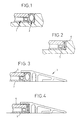
Ein Ausführungsbeispiel der Erfindung wird nachfolgend anhand der Zeichnungen erläutert. Die Zeichnungen zeigen dabei in den
- Fig. 1 und 2
- im Bereich einer Wandbegrenzung angeordnete Dämpfungselemente für eine Schaltmatte und in den
- Fig. 3 und 4
- im Bereich eines Rampenprofiles eingesetzte Dämpfungselemente.
- 1 and 2
- Damping elements arranged in the area of a wall boundary for a switch mat and in the
- 3 and 4
- Damping elements used in the area of a ramp profile.
In den Zeichnungen ist jeweils der Ruhezustand und der Zustand dargestellt, in dem das Dämpfungselement zusammengepresst ist.The drawings show the state of rest and the state shown in which the damping element is compressed is.
In den Zeichnungen ist eine Schaltmatte 1 dargestellt, die beispielsweise
an eine Wandbegrenzung 4 oder an ein Rampenprofil
3 angrenzt, wobei selbstverständlich von der Erfindung
mitumfasst wird, dass auch eine Schaltmatte 1 an eine andere
Schaltmatte 1 angrenzen kann.In the drawings, a
In den Raum zwischen den dann aneinander angrenzenden
Schaltmatten 1 oder der Wandbegrenzung 4 oder dem Rampenprofil
3 ist ein Dämpfungselement 2 eingesetzt, das aus
einem Hohlprofil besteht und beispielsweise einen Einsteckzapfen
5 aufweist, mit dem dieses Dämpfungselement 2 zwischen
eine Deckplatte 6 und eine Bodenplatte 7 der Schaltmatte
1 eingesetzt werden kann. Dehnt sich nun - wie in Fig. 2 und
Fig. 4 dargestellt - die Schaltmatte 1 aus irgendeinem Grunde
aus, nimmt das Dämpfungselement 2 diese Ausdehnung auf,
indem sich das Dämpfungselement 2 zusammendrückt, wobei
also im Einbauzustand gemäß Fig. 1 und 3 sichergestellt ist,
dass in den Raum zwischen Schaltmatte, Wandbegrenzung,
Rampenprofil oder Schaltmatte keine Fremdkörper eintreten
können, andererseits sichergestellt ist, dass bei einer Materialdehnung
der Schaltmatte 1 das Dämpfungsprofil 2 dieser
Raumminderung nachgeben kann und trotzdem den vorhandenen
Zwischenraum wirksam abdichtet.In the space between those then
In das als Hohlprofil ausgebildete Dämpfungselement 1 kann eine
Schaltleiste eingesetzt werden, wie sie beispielsweise aus
der DE 100 02 926 C1 bekannt ist oder auch in anderer Form
zum Stand der Technik gehört, so dass in diesem Bereich noch
eine Absicherung zusätzlich zu der normalen Absicherung durch
die Schaltmatte kommt.In the
Claims (4)
Applications Claiming Priority (2)
| Application Number | Priority Date | Filing Date | Title |
|---|---|---|---|
| DE20103732U DE20103732U1 (en) | 2001-03-03 | 2001-03-03 | Pressure-sensitive switching device in the form of a flat safety mat |
| DE20103732U | 2001-03-03 |
Publications (2)
| Publication Number | Publication Date |
|---|---|
| EP1237168A2 true EP1237168A2 (en) | 2002-09-04 |
| EP1237168A3 EP1237168A3 (en) | 2004-04-28 |
Family
ID=7953803
Family Applications (1)
| Application Number | Title | Priority Date | Filing Date |
|---|---|---|---|
| EP01108562A Withdrawn EP1237168A3 (en) | 2001-03-03 | 2001-04-05 | A pressure-sensitive switch assembly in the form of a conductive strip switch |
Country Status (2)
| Country | Link |
|---|---|
| EP (1) | EP1237168A3 (en) |
| DE (1) | DE20103732U1 (en) |
Cited By (1)
| Publication number | Priority date | Publication date | Assignee | Title |
|---|---|---|---|---|
| EP1437752A1 (en) * | 2003-01-13 | 2004-07-14 | Bircher Reglomat AG | Mat switch |
Families Citing this family (2)
| Publication number | Priority date | Publication date | Assignee | Title |
|---|---|---|---|---|
| DE10155466A1 (en) * | 2001-11-12 | 2003-05-22 | Karlheinz Beckhausen | Closing edge safety profile |
| DE10306436A1 (en) * | 2003-02-15 | 2004-08-26 | Menz, Jürgen | safety device |
Family Cites Families (4)
| Publication number | Priority date | Publication date | Assignee | Title |
|---|---|---|---|---|
| DE7342245U (en) * | 1973-11-27 | 1974-03-28 | Erhardt & Leimer Kg | Contact bottom |
| DE3932820C1 (en) * | 1989-09-30 | 1990-10-25 | Haake, Andre | |
| US5510586A (en) * | 1995-01-11 | 1996-04-23 | Tapeswitch Corporation Of America | Switch joint for electrical switching mats |
| DE10002926C1 (en) * | 2000-01-25 | 2001-01-25 | Andre Haake | Safety switch rail for closure edge has contact points between contact lines within serial switch elements along deformable hose separated by hose deformation |
-
2001
- 2001-03-03 DE DE20103732U patent/DE20103732U1/en not_active Expired - Lifetime
- 2001-04-05 EP EP01108562A patent/EP1237168A3/en not_active Withdrawn
Cited By (1)
| Publication number | Priority date | Publication date | Assignee | Title |
|---|---|---|---|---|
| EP1437752A1 (en) * | 2003-01-13 | 2004-07-14 | Bircher Reglomat AG | Mat switch |
Also Published As
| Publication number | Publication date |
|---|---|
| EP1237168A3 (en) | 2004-04-28 |
| DE20103732U1 (en) | 2001-06-21 |
Similar Documents
| Publication | Publication Date | Title |
|---|---|---|
| DE19828417C2 (en) | Arc extinguishing system for a switching device | |
| DE3601363A1 (en) | ELECTRICAL SWITCHING ELEMENT | |
| DE102014004843A1 (en) | DC contactor with additional switching capability for AC loads and polarity against the preferred direction of current | |
| DE3331594C2 (en) | ||
| DE3740592C2 (en) | ||
| EP0774800B1 (en) | Cross connection for series terminals | |
| DE3715871C2 (en) | ||
| EP1237168A2 (en) | A pressure-sensitive switch assembly in the form of a conductive strip switch | |
| DE3101532A1 (en) | SOCKET BASE FOR LOW VOLTAGE CIRCUIT BREAKERS | |
| EP0421048A1 (en) | Safety edge | |
| DE4312682C2 (en) | Protection against accidental contact for power distribution rails | |
| DE3019925C2 (en) | NH fuse disconnectors and load switches | |
| DE3409564A1 (en) | Arc extinguishing device | |
| DE19918747C1 (en) | Pressure sensitive switching device | |
| DE8227325U1 (en) | Electrical switchgear with locking device | |
| DE19544075C2 (en) | Protection device for electrical systems | |
| EP1366501A1 (en) | Low-voltage circuit breaker with an electric arc extinction system | |
| DE3902779A1 (en) | Structural unit for accommodating electrical components | |
| DE2136693C3 (en) | cover | |
| DE20106688U1 (en) | Coding of device racks | |
| DE102005063606B3 (en) | Mechanical coding between battery pack and power tool | |
| DE3416921C2 (en) | Electrical switching device | |
| DE2148985B2 (en) | Electric appts. cover plate or sub-chassis - has partially cut-through sections to form orifices for sockets screw caps | |
| DE3445679A1 (en) | Housing for receiving a control board for coin-operated gaming machines | |
| DE8601165U1 (en) | Electrical switching element |
Legal Events
| Date | Code | Title | Description |
|---|---|---|---|
| PUAI | Public reference made under article 153(3) epc to a published international application that has entered the european phase |
Free format text: ORIGINAL CODE: 0009012 |
|
| AK | Designated contracting states |
Kind code of ref document: A2 Designated state(s): AT BE CH CY DE DK ES FI FR GB GR IE IT LI LU MC NL PT SE TR |
|
| AX | Request for extension of the european patent |
Free format text: AL;LT;LV;MK;RO;SI |
|
| PUAL | Search report despatched |
Free format text: ORIGINAL CODE: 0009013 |
|
| STAA | Information on the status of an ep patent application or granted ep patent |
Free format text: STATUS: THE APPLICATION HAS BEEN WITHDRAWN |
|
| AK | Designated contracting states |
Kind code of ref document: A3 Designated state(s): AT BE CH CY DE DK ES FI FR GB GR IE IT LI LU MC NL PT SE TR |
|
| AX | Request for extension of the european patent |
Extension state: AL LT LV MK RO SI |
|
| 18W | Application withdrawn |
Effective date: 20040319 |