EP1237167A2 - Push button switch for irreversibly closing an electric circuit and low voltage lighting unit or bottlelike houseware using the same - Google Patents
Push button switch for irreversibly closing an electric circuit and low voltage lighting unit or bottlelike houseware using the same Download PDFInfo
- Publication number
- EP1237167A2 EP1237167A2 EP01127459A EP01127459A EP1237167A2 EP 1237167 A2 EP1237167 A2 EP 1237167A2 EP 01127459 A EP01127459 A EP 01127459A EP 01127459 A EP01127459 A EP 01127459A EP 1237167 A2 EP1237167 A2 EP 1237167A2
- Authority
- EP
- European Patent Office
- Prior art keywords
- blind hole
- lighting unit
- battery
- pressure switch
- holder
- Prior art date
- Legal status (The legal status is an assumption and is not a legal conclusion. Google has not performed a legal analysis and makes no representation as to the accuracy of the status listed.)
- Withdrawn
Links
Images


Classifications
-
- A—HUMAN NECESSITIES
- A47—FURNITURE; DOMESTIC ARTICLES OR APPLIANCES; COFFEE MILLS; SPICE MILLS; SUCTION CLEANERS IN GENERAL
- A47G—HOUSEHOLD OR TABLE EQUIPMENT
- A47G7/00—Flower holders or the like
- A47G7/02—Devices for supporting flower-pots or cut flowers
- A47G7/06—Flower vases
-
- A—HUMAN NECESSITIES
- A47—FURNITURE; DOMESTIC ARTICLES OR APPLIANCES; COFFEE MILLS; SPICE MILLS; SUCTION CLEANERS IN GENERAL
- A47G—HOUSEHOLD OR TABLE EQUIPMENT
- A47G19/00—Table service
- A47G19/22—Drinking vessels or saucers used for table service
- A47G19/2205—Drinking glasses or vessels
- A47G19/2227—Drinking glasses or vessels with means for amusing or giving information to the user
-
- H—ELECTRICITY
- H01—ELECTRIC ELEMENTS
- H01H—ELECTRIC SWITCHES; RELAYS; SELECTORS; EMERGENCY PROTECTIVE DEVICES
- H01H9/00—Details of switching devices, not covered by groups H01H1/00 - H01H7/00
- H01H9/02—Bases, casings, or covers
-
- A—HUMAN NECESSITIES
- A47—FURNITURE; DOMESTIC ARTICLES OR APPLIANCES; COFFEE MILLS; SPICE MILLS; SUCTION CLEANERS IN GENERAL
- A47G—HOUSEHOLD OR TABLE EQUIPMENT
- A47G19/00—Table service
- A47G19/22—Drinking vessels or saucers used for table service
- A47G19/2205—Drinking glasses or vessels
- A47G19/2227—Drinking glasses or vessels with means for amusing or giving information to the user
- A47G2019/2238—Drinking glasses or vessels with means for amusing or giving information to the user with illumination means
-
- F—MECHANICAL ENGINEERING; LIGHTING; HEATING; WEAPONS; BLASTING
- F21—LIGHTING
- F21V—FUNCTIONAL FEATURES OR DETAILS OF LIGHTING DEVICES OR SYSTEMS THEREOF; STRUCTURAL COMBINATIONS OF LIGHTING DEVICES WITH OTHER ARTICLES, NOT OTHERWISE PROVIDED FOR
- F21V33/00—Structural combinations of lighting devices with other articles, not otherwise provided for
- F21V33/0004—Personal or domestic articles
- F21V33/0024—Household or table equipment
- F21V33/0036—Table-ware or table equipment, e.g. dishes, cutlery or trays
-
- F—MECHANICAL ENGINEERING; LIGHTING; HEATING; WEAPONS; BLASTING
- F21—LIGHTING
- F21Y—INDEXING SCHEME ASSOCIATED WITH SUBCLASSES F21K, F21L, F21S and F21V, RELATING TO THE FORM OR THE KIND OF THE LIGHT SOURCES OR OF THE COLOUR OF THE LIGHT EMITTED
- F21Y2115/00—Light-generating elements of semiconductor light sources
- F21Y2115/10—Light-emitting diodes [LED]
-
- H—ELECTRICITY
- H01—ELECTRIC ELEMENTS
- H01H—ELECTRIC SWITCHES; RELAYS; SELECTORS; EMERGENCY PROTECTIVE DEVICES
- H01H3/00—Mechanisms for operating contacts
- H01H3/02—Operating parts, i.e. for operating driving mechanism by a mechanical force external to the switch
- H01H2003/0273—Manually irreversibly actuated switch
Definitions
- the present invention relates to a Pressure switch for irreversibly switching on a electrical circuit, preferably Low voltage circuit, according to the preamble of Claim 1.
- the object of the present invention is a Pressure switch for irreversibly switching on a electrical circuit, preferably Low-voltage circuit of the type mentioned create the while reducing necessary components in is simple and inexpensive to implement.
- the present invention further relates to a a pressure switch provided lighting unit according to claim 6th
- Such a lighting unit can be very inexpensive be built up because the necessary number of components is reduced to a minimum. So the record does not have only a holder for the battery and serves as a holder the light emitting diode but it is also in one piece with the axially movable actuator provided at Manufacture of the plate is automatically produced with so that subsequent assembly is not necessary.
- the invention relates to one in a simple manner vessel-like object equipped with a light unit according to claim 14.
- This connection option can either be a permanent connection or used for that the connection with the recording of the vessel-like Object is lifted again.
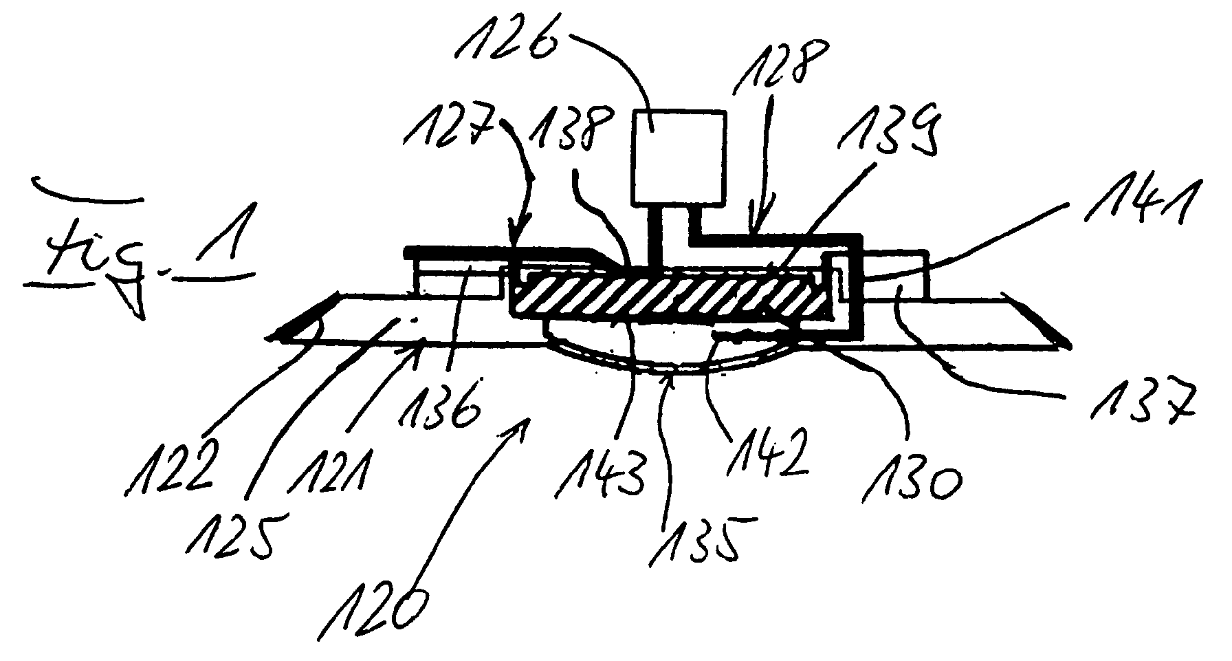
- the pressure switch 120 has a plate-shaped holder 121, the outer peripheral edge of which 122 to the area of the boundary surface of a housing or can be adapted to another object, in which the holder 121 is to be arranged.
- an electrical preferably Low voltage circuit provided with Switch contacts 127, 128 of the pressure switch 120 connected is.
- the recess 129 has the shape of a step Blind hole that ends at a curved bottom 135.
- the blind hole 129 is at a distance of arched bottom 135 an annular shoulder 131 on which the Button cell 130 is present.
- the integrally molded holder 121 has one with the Outer peripheral edge 122 provided washer 125 and one concentric central axial ring 132 which the Blind hole 129 forms with.
- the ring 132 goes to two diametrically opposite areas in T-shaped Approaches 133 and 134 respectively.
- a T-shaped Neck 133 is a radial groove 136 from ring neck 132 provided starting while diametrically opposite a reaching up to the curved bottom 135 of the disc 125 and provided in front of this ending radial slot 137 is that in the annular shoulder 131, the axial ring approach 132 and partially in the other T-shaped extension 134 is incorporated.
- the one switch contact 127 in the radial groove 136 held in such a way that a bent region 138 on the top, i.e. one pole 139 of the battery 130 supported.
- the other switch contact 128 is U-shaped bent so that its axial leg 141 in radial slot 137 is located and its radial free End 142 between the bottom, i.e. the lower pole 143 of the battery 130 and the curved bottom 135. This radial end 142 extends approximately over half Diameter of the blind hole recess 129.
- the axial leg 141 can be held stationary in the radial slot 137 his.
- the convex curvature of the relatively thin bottom 135 protrudes the underside 144 of the disc 125.
- the curved bottom 135 serves as an actuator for switching on Circuit 126 and thus for electrically connecting the Switching contact 128 with the lower pole 143 here Battery 130.
- the curved bottom 135 is on the outside with a slightly larger radius than inside Mistake.
- the curved bottom 135 has that in FIG. 1 or 3 shown stable starting position and can corresponding to Figure 3 in a dashed line stable switch position are brought about by the fact that by pressing the finger (arrow D) the curved bottom 135 this starting position in the inwardly projecting position stable snaps.
- the battery is not shown in detail 130 caulked within the blind hole recess 129, i.e. arranged undetachable or not detachable.
- the disk 125 with four at an equal distance arranged radial wedge-shaped depressions 146 provided that cause a violent Breaking out of the battery 130 from the blind hole 129 the disc 125 in the area of the wedge-shaped Recesses 146, which serve as predetermined breaking points, breaks.
- the depressions can also be ring-shaped around the Battery holder.
- the electrical circuit 126 be of any type or have any structure can, for example, as a relay circuit Switching on circuits can serve. It goes without saying further that the here between the two switch contacts 127 and 128 arranged battery 130 by a Metal plate can be replaced if the circuit 126 to be controlled has its own power supply having. In this case it is also possible without Interpose a plate 130 the free ends of the Switch contacts in such a short distance from each other to contrast that when the Floor or actuator 135, the free end of a switching contact 127 in electrical contact system reaches the free end of the other switching contact 128. In In this case it makes sense to have the free end of one Switching contact 127 can be moved elastically and the free end of the other switching contact 128 is essentially rigid embody.
- the essence of the pressure switch 120 for irreversible Switching on an electrical circuit, preferably Low voltage circuit is that the domed Floor or the axially movable actuator 135 its stable starting position in an irreversible stable switch position can snap and in this Switching position the closed contact between the switch contacts 127 and 128 holds.
- FIGS. 4 and 5 show, for example, application of a Pressure switch 120 a vessel-like object in the form a beverage bottle 10, for example a champagne bottle green, light, blue or the like glass, the body 11, Neck 12 and bottom 13 are shaped in a known manner.
- the Bottom 13 has a concave curvature 14 which a frustoconical exterior space 15 between itself and leaves an annular support surface 16 free.
- a pressure switch 120 Luminous unit 20 used so that it with the Support surface 16 closes, for example, but preferably in a distance from this inwards into the outer space 15 is staggered.
- the lighting unit 20 has a lot low voltage which the pressure switch 120 and as electrical circuit 126 has a lamp 26, a plate-shaped holder 21, the outer peripheral edge 22nd to the area of the boundary surface of the curvature 14 is adapted in which the holder 21 is to be arranged.
- the holder 21 has an exemplary embodiment beveled or conical outer peripheral edge 22 which with an adhesive layer 23 or a double-sided adhesive tape is coated or coated.
- the Holder 21 in the outer space 15 to the boundary surface of the Bulge 14 are preferably releasably glued.
- the holder 21 is in the essentially identical to the holder 121 according to the figures 1 to 3.
- the Recess 29 has the shape of a stepped Blind hole that ends at a curved bottom 35.
- the Blind hole has an arched distance Bottom 35 an annular shoulder 31 on which the button cell 30th is applied.
- the connecting leg 27 of the LED 26 in the radial groove 36 held so that a bent area 38 on the top, i.e. the one Pol 39 of the battery 30 supports.
- the other leg 28 is bent in a U-shape so that the axial leg 41 of the connecting leg 28 is located in the radial slot 37 and the radial end 42 of the leg 28 between the Bottom, i.e. the lower pole 43 of the battery 30 and the curved bottom 35 extends.
- This radial end 42 extends about half the diameter of the Blind hole recess 29.
- the axial leg 41 of the Light-emitting diode 26 can be stationary in the radial slot 37 be kept.
- the disc 25 can at a distance from the ring shoulder 32 and between the T-shaped lugs 33 and 34 Have through holes that the one on the inside of the disc 25 can be arranged and not serve electronic additional device shown can, for example, cause the LED 26 to flash can.
- the light emitting diode 26 can shine white or any have a different color. It goes without saying that more can be provided as a light-emitting diode 26 on the holder 21. Furthermore, it is understood that the light emitting diode 26 another light source can be replaced, in particular when the outer space 15 or the concave curvature 14 is relatively small or flat.
- the holder 21 it is also possible for the holder 21 to be curved in this way 14 of an object 10 that the arched Bottom 35 of the holder 21 or an outside of it molded pin the bearing surface 16 of the object 10 towers over, so with putting on the with the Lighting unit 20 provided object 10 the arched Floor 35 operated and thus the LED 26 switched on becomes.
- This can be done in the manner described above that the curved bottom 35 in the form of the actuator from its stable starting position to its stable Switched on position.
- domed bottom 34 with an approach to the inside provided that only an unstable switching position of the curved floor or actuator 35 allows. On in this way, the LED 26 goes out when the Item 10 is raised.
- the one with the light unit 20 stocked household items can be made of glass, plastic or another transparent or translucent Material. Therefore, the holder 21 can also rectangular, elliptical or the like shaped disk 25 have.
Landscapes
- Arrangement Of Elements, Cooling, Sealing, Or The Like Of Lighting Devices (AREA)
- Cookers (AREA)
Abstract
Ein Druckschalter (120) zum irreversiblen Zuschalten eines
elektrischen Stromkreises (126) ist mit einem ersten und
einem zweiten Schaltkontakt (127, 128), die in einem Halter
(121) angeordnet sind und die einenends mit dem Stromkreis
(126) verbunden und andernends über ein axial bewegbares
Betätigungselement (135) elektrisch mittelbar oder
unmittelbar kontaktierend verbindbar sind, versehen. Um
einen derartigen Druckschalter unter Reduzierung
notwendiger Bauelemente in einfacher und kostengünstigere
Weise zu realisieren, ist vorgesehen, dass der Halter (121)
aus elektrisch isolierendem Material mit einer axialen
Sacklochausnehmung (129) versehen ist, in die das freie
Ende mindestens eines der beiden Schaltkontakte (127, 128)
ragt, und dass der Boden (135) der Sacklochbohrung (129) in
seiner Ausgangsstellung zur Bildung des axial beweglichen
Betätigungselementes dünnwandig und außenseitig konvex
derart ausgebildet ist, dass er bzw. es auf axialen Druck
in eine stabile in die Sacklochbohrung (129) mit seiner nun
konvexen Innenseite ragende Zuschaltstellung schnappt.
Description
Die vorliegende Erfindung bezieht sich auf einen
Druckschalter zum irreversiblen Zuschalten eines
elektrischen Stromkreises, vorzugsweise
Niederspannungsstromkreises, nach dem Oberbegriff des
Anspruchs 1.The present invention relates to a
Pressure switch for irreversibly switching on a
electrical circuit, preferably
Low voltage circuit, according to the preamble of
Es sind Druckschalter bekannt, die zum Ein- und zum Ausschalten eines elektrischen Stromkreises dienen, wie dies bspw. in der DE 198 42 893 A1 offenbart ist. In vielen Fällen, wie bspw. bei der Notbetätigung von Alarmstromkreisen, Maschinenstromkreisen und dgl., soll der zugeschaltete Zustand irreversibel sein. Dies wird bisher über relativ aufwendige Druckschalter erreicht.There are pressure switches known for the on and Turning off an electrical circuit serve as this is disclosed, for example, in DE 198 42 893 A1. In many Cases, such as in the emergency operation of Alarm circuits, machine circuits and the like switched on state can be irreversible. So far achieved via relatively complex pressure switches.
Aufgabe der vorliegenden Erfindung ist es, einen Druckschalter zum irreversiblen Zuschalten eines elektrischen Stromkreises, vorzugsweise Niederspannungsstromkreises der eingangs genannten Art zu schaffen, der unter Reduzierung notwendiger Bauelemente in einfacher und kostengünstiger Weise zu realisieren ist.The object of the present invention is a Pressure switch for irreversibly switching on a electrical circuit, preferably Low-voltage circuit of the type mentioned create the while reducing necessary components in is simple and inexpensive to implement.
Zur Lösung dieser Aufgabe sind bei einem Druckschalter der
genannten Art die im Anspruch 1 angegebenen Merkmale
vorgesehen.To solve this problem are the pressure switch
mentioned type the features specified in
Durch die erfindungsgemäßen Maßnahmen ist ein mit einer minimalen Anzahl von Bauteilen auskommender Druckschalter erreicht, da das Betätigungselement zusammen mit dem gehäuseartigen Halter in schneller und einfacher Weise hergestellt ist. Das mit dem Halter einstückige Betätigungselement wirkt somit unmittelbar auf einen der beiden Schaltkontakte, der über das Betätigungselement bewegbar und mittelbar oder unmittelbar mit dem anderen Schaltkontakt in elektrische Verbindung bringbar ist. Through the measures according to the invention, one with a minimal number of pressure switches reached because the actuator together with the housing-like holder in a quick and easy way is made. The one piece with the holder Actuator thus acts directly on one of the two switch contacts, the one over the actuator movable and indirect or direct with the other Switch contact can be brought into electrical connection.
Je nach Anwendung kann der betätigbare Boden bzw. das Betätigungselement umfangsseitig geschützt oder entsprechend den Merkmalen nach Anspruch 2 ausgebildet sein. Eine vorteilhafte Anordnung der Schaltkontakte am Halter ergibt sich durch die Merkmale des Anspruchs 3 und ggf. des Anspruchs 4.Depending on the application, the operable floor or Actuator protected on the circumference or formed according to the features of claim 2 his. An advantageous arrangement of the switch contacts on Holder results from the features of claim 3 and if applicable, of claim 4.
Eine vorteilhafte Halterung der Schaltkontakte am Halter ergibt sich durch die Merkmale nach Anspruch 5.An advantageous mounting of the switch contacts on the holder results from the features of claim 5.
Die vorliegende Erfindung bezieht sich ferner auf eine mit einem Druckschalter versehene Leuchteinheit nach Anspruch 6.The present invention further relates to a a pressure switch provided lighting unit according to claim 6th
Eine derartige Leuchteinheit kann sehr kostengünstig aufgebaut werden, weil die notwendige Anzahl an Bauelemente auf ein Minimum reduziert ist. So besitzt die Platte nicht nur eine Aufnahme für die Batterie und dient der Halterung der Leuchtdiode sondern sie ist auch einstückig mit dem axial bewegbaren Betätigungselement versehen, das bei der Herstellung der Platte automatisch mit gefertigt wird, so dass eine nachträgliche Montage entfällt.Such a lighting unit can be very inexpensive be built up because the necessary number of components is reduced to a minimum. So the record does not have only a holder for the battery and serves as a holder the light emitting diode but it is also in one piece with the axially movable actuator provided at Manufacture of the plate is automatically produced with so that subsequent assembly is not necessary.
In besonders einfacher und vorteilhafter Weise sind die Merkmale nach Anspruch 7 vorgesehen, so dass besondere Schalterelemente entfallen können. Besondere Ausgestaltungen hinsichtlich der Lage der Batterie in der Sacklochbohrung ergeben sich aus den Merkmalen eines oder mehrerer oder Ansprüche 8 bis 11.These are in a particularly simple and advantageous manner Features provided according to claim 7, so that special Switch elements can be omitted. Special Refinements regarding the location of the battery in the Blind holes result from the characteristics of a or several or claims 8 to 11.
Vorteilhafte Ausgestaltungen der Halterung und Anordnung
des Leuchtkörpers und dessen elektrischen Anschlüsse ergibt
sich aus den Merkmalen des Anspruchs 12.Advantageous configurations of the holder and arrangement
of the filament and its electrical connections
derive from the features of
Mit den Merkmalen nach Anspruch 13 ist in einfacher Weise
die Leuchteinheit als sogenannter Wegwerfartikel
ausgebildet.With the features of
Desweiteren betrifft die Erfindung einen in einfacher Weise
mit einer Leuchteinheit bestückten gefäßartigen Gegenstand
nach Anspruch 14.Furthermore, the invention relates to one in a simple manner
vessel-like object equipped with a light unit
according to
Vorteilhafte Ausgestaltungen ergeben sich dabei durch die
Merkmale des Anspruchs 15 und/oder 16.Advantageous configurations result from the
Features of
Mit den Merkmalen nach Anspruch 17 ist erreicht, dass mit dem Aufstellen des gefäßartigen Gegenstandes in automatischer Weise die Leuchteinheit zugeschaltet wird. Dabei kann diese Zuschaltmöglichkeit entweder zu einer dauerhaften Zuschaltung oder dazu verwendet werden, dass die Zuschaltung mit dem Aufnehmen des gefäßartigen Gegenstandes wieder aufgehoben ist. With the features of claim 17 it is achieved that with the installation of the vessel-like object in the lighting unit is switched on automatically. This connection option can either be a permanent connection or used for that the connection with the recording of the vessel-like Object is lifted again.
Weitere Einzelheiten der Erfindung sind der folgenden Beschreibung zu entnehmen, in der die Erfindung anhand des in der Zeichnung dargestellten Ausführungsbeispieles näher beschrieben und erläutert ist. Es zeigen:
Figur 1- in teilweise längsgeschnittener Darstellung einen Druckschalter zum irreversiblen Zuschalten eines Stromkreises, bspw. einer Leuchteinheit, gemäß einem bevorzugten Ausführungsbeispiel vorliegender Erfindung,
- Figur 2
- eine Draufsicht auf die Grundplatte des Druckschalters,
- Figur 3
- einen Schnitt längs der Linie III-III der Figur 2,
- Figur 4
- in teilweise längsgeschnittener Seitenansicht
eine mit einer mit Druckschalter nach
Figur 1 versehenen Leuchteinheit bestückte Getränkeflache und - Figur 5
- in vergrößerter längsgeschnittener Darstellung
den mit dem Druckschalter und der Leuchteinheit
versehenen Bodenbereich der Getränkeflasche nach
Figur 1.
- Figure 1
- a partially longitudinally sectioned illustration of a pressure switch for irreversibly switching on a circuit, for example a lighting unit, according to a preferred embodiment of the present invention,
- Figure 2
- a plan view of the base plate of the pressure switch,
- Figure 3
- 3 shows a section along the line III-III of FIG. 2
- Figure 4
- In a partially longitudinally sectioned side view, a beverage area equipped with a lighting unit provided with a pressure switch according to FIG. 1 and
- Figure 5
- in an enlarged longitudinal section the bottom area of the beverage bottle according to FIG. 1 provided with the pressure switch and the lighting unit.
Gemäß den Figuren 1 bis 3 besitzt der Druckschalter 120
einen plattenförmigen Halter 121, dessen Außenumfangsrand
122 an den Bereich der Begrenzungsfläche eines Gehäuses
oder eines sonstigen Gegenstandes angepaßt sein kann, in
welchen der Halter 121 anzuordnen ist.According to FIGS. 1 to 3, the
An der Innenfläche 124 des Halters 121 ist, durch einen
Block 126 angedeutet, ein elektrischer vorzugsweise
Niederspannungsstromkreis vorgesehen, der mit
Schaltkontakten 127, 128 des Druckschalters 120 verbunden
ist. Von der Innenfläche 124 her ist in den Halter 121 eine
Ausnehmung 129 eingearbeitet, in die eine Batterie in Form
einer Knopfzelle 130 eingesetzt und fixiert gehalten ist.
Die Ausnehmung 129 besitzt die Form einer gestuften
Sacklochbohrung, die an einem gewölbten Boden 135 endet.
Die Sacklochbohrung 129 besitzt in einem Abstand von
gewölbten Boden 135 eine Ringschulter 131, an der die
Knopfzelle 130 anliegt.Is on the
Der einstückig geformte Halter 121 besitzt eine mit dem
Außenumfangsrand 122 versehene Scheibe 125 und einen dazu
konzentrischen mittigen axialen Ring 132, der die
Sacklochbohrung 129 mit bildet. Der Ring 132 geht an zwei
einander diametral gegenüberliegenden Bereichen in T-förmige
Ansätze 133 bzw. 134 über. Im einen T-förmigen
Ansatz 133 ist eine radiale Nut 136 vom Ringansatz 132
ausgehend vorgesehen, während diametral gegenüberliegend
ein bis zum gewölbten Boden 135 der Scheibe 125 reichender
und vor diesem endender radialer Schlitz 137 vorgesehen
ist, der in die Ringschulter 131, den axialen Ringansatz
132 und teilweise in den anderen T-förmigen Ansatz 134
eingearbeitet ist.The integrally molded
Wie der zeichnerischen Darstellung der Fig. 1 zu entnehmen
ist, ist der eine Schaltkontakt 127 in der radialen Nut 136
derart festgehalten, dass sich ein umgebogener Bereich 138
auf der Oberseite, d.h. dem einen Pol 139 der Batterie 130
abstützt. Der andere Schaltkontakt 128 ist U-förmig
gebogen, so dass sich dessen axialer Schenkel 141 im
radialen Schlitz 137 befindet und dessen radiales freies
Ende 142 zwischen der Unterseite, d.h. dem unteren Pol 143
der Batterie 130 und dem gewölbten Boden 135 erstreckt.
Dieses radiale Ende 142 erstreckt sich etwa über den halben
Durchmesser der Sacklochausnehmung 129. Der axiale Schenkel
141 kann in dem radialen Schlitz 137 ortsfest gehalten
sein.As can be seen in the graphic representation of FIG. 1
is the one
Die konvexe Wölbung des relativ dünnen Bodens 135 überragt
die Unterseite 144 der Scheibe 125. Der gewölbte Boden 135
dient als Betätigungselement zum Zuschalten des
Schaltkreises 126 und damit zum elektrischen Verbinden des
Schaltkontaktes 128 mit dem hier unteren Pol 143 der
Batterie 130. Bspw. ist der gewölbte Boden 135 außenseitig
mit einem geringfügig größeren Radius als innenseitig
versehen. Der gewölbte Boden 135 besitzt die in Figur 1
bzw. 3 dargestellte stabile Ausgangsstellung und kann
entsprechend Figur 3 in eine gestrichelt dargestellte
stabile Zuschaltstellung dadurch gebracht werden, dass
durch Fingerdruck (Pfeil D) der gewölbte Boden 135 aus
dieser Ausgangslage in die nach innen ragende Lage stabil
umschnappt. In dieser stabilen Zuschaltstellung drückt der
in flexibler Weise sich axial bewegende Boden 135 das
radiale freie Ende 142 des Schaltkontaktes 128 gegen den
unteren Pol 143 der Batterie 130, so dass der elektrische
Stromkreis für eine Notanzeige oder dgl. geschlossen ist.
Diese stabile Zuschaltstellung kann nicht verändert werden.The convex curvature of the relatively
In nicht im einzelnen dargestellter Weise ist die Batterie
130 innerhalb der Sacklochausnehmung 129 verstemmt, d.h.
unlösbar bzw. nicht herauslösbar angeordnet. Um ein
gewaltsames Herauslösen der Batterie 130 zu verhindern, ist
die Scheibe 125 mit vier in gleichmäßigem Abstand
angeordneten radialen keilförmigen Vertiefungen 146
versehen, die bewirken, dass bei einem gewaltsamen
Herausbrechen der Batterie 130 aus der Sacklochausnehmung
129 die Scheibe 125 im Bereich der keilförmigen
Vertiefungen 146, die als Sollbruchstellen dienen, bricht.
Die Vertiefungen können auch ringförmig um die
Batterieaufnahme liegen.The battery is not shown in
Es versteht sich, dass der elektrische Schaltkreis 126
beliebiger Art sein bzw. ein beliebigen Aufbau besitzen
kann und beispielsweise als Relaiskreis seinerseits dem
Zuschalten von Stromkreisen dienen kann. Es versteht sich
ferner, dass die hier zwischen den beiden Schaltkontakten
127 und 128 angeordnete Batterie 130 durch eine
Metallplatte dann ersetzt werden kann, wenn der
anzusteuernde Stromkreis 126 eine eigene Stromversorgung
aufweist. In diesem Falle ist es auch möglich, ohne
Zwischenfügen einer Platte 130 die freien Enden der
Schaltkontakte derart in geringem Abstand einander
gegenüber zu stellen, dass bei betätigendem Umschnappen des
Bodens bzw. Betätigungselementes 135 das freie Ende des
einen Schaltkontaktes 127 in elektrische Kontaktanlage mit
dem freien Ende des anderen Schaltkontakts 128 gelangt. In
diesem Falle ist es sinnvoll, das freie Ende des einen
Schaltkontakts 127 elastisch bewegbar und das freie Ende
des anderen Schaltkontaktes 128 im wesentlichen starr
auszugestalten.It is understood that the
Das Wesentliche an dem Druckschalter 120 zum irreversiblen
Zuschalten eines elektrischen Stromkreises, vorzugsweise
Niederspannungs-Stromkreises liegt darin, dass der gewölbte
Boden bzw. das axial bewegbare Betätigungselement 135 aus
seiner stabilen Ausgangsstellung in eine irreversible
stabile Schaltstellung umschnappen kann und in dieser
Umschaltstellung die geschlossene Kontaktierung zwischen
den Schaltkontakten 127 und 128 hält.The essence of the
Figuren 4 und 5 zeigen in bspw. Anwendung eines
Druckschalters 120 einen gefäßartigen Gegenstand in Form
einer Getränkeflasche 10, bspw. einer Sektflasche aus
grünem, hellem, blauem oder dgl. Glas, deren Korpus 11,
Hals 12 und Boden 13 in bekannter Weise geformt sind. Der
Boden 13 besitzt eine konkav eingezogene Wölbung 14, die
einen kegelstumpfartigen Außenraum 15 zwischen sich und
einer ringförmigen Auflagefläche 16 freiläßt. In diesen
Außenraum 15 ist eine mit einem Druckschalter 120 bestückte
Leuchteinheit 20 derart eingesetzt, dass sie mit der
Auflagefläche 16 bspw. abschließt, vorzugsweise jedoch in
einem Abstand von dieser nach innen in den Außenraum 15
versetzt angeordnet ist.FIGS. 4 and 5 show, for example, application of a
Pressure switch 120 a vessel-like object in the form
a beverage bottle 10, for example a champagne bottle
green, light, blue or the like glass, the
Gemäß der Zeichnung besitzt die Leuchteinheit 20 sehr
geringer Spannung, die den Druckschalter 120 und als
elektrischen Stromkreis 126 ein Leuchtmittel 26 aufweist,
einen plattenförmigen Halter 21, dessen Außenumfangsrand 22
an den Bereich der Begrenzungsfläche der Wölbung 14
angepaßt ist, in welche der Halter 21 anzuordnen ist. Beim
Ausführungsbeispiel besitzt der Halter 21 einen
abgeschrägten bzw. konischen Außenumfangsrand 22, der mit
einer Klebeschicht 23 oder einem doppelseitigen Klebeband
beschichtet bzw. belegt ist. Auf diese Weise kann der
Halter 21 in den Außenraum 15 an die Begrenzungsfläche der
Wölbung 14 vorzugsweise lösbar eingeklebt werden. Außerdem
läßt sich so die Getränkeflasche 10 benutzen, ohne dass die
Leuchteinheit 20 herausfällt. Der Halter 21 ist im
wesentlichen identisch mit dem Halter 121 nach den Figuren
1 bis 3.According to the drawing, the
Von der Innenfläche 24 des Halters 21 steht das
Leuchtmittel in Form einer Leuchtdiode (LED) 26 vor, die
mit Anschlußbeinen 27, 28 versehen ist. Von der Innenfläche
24 her ist in den Halter 21 eine Ausnehmung 29
eingearbeitet, in die eine Batterie in Form einer
Knopfzelle 30 eingesetzt und fixiert gehalten ist. Die
Ausnehmung 29 besitzt die Form einer gestuften
Sacklochbohrung, die an einem gewölbten Boden 35 endet. Die
Sacklochbohrung besitzt in einem Abstand von gewölbten
Boden 35 eine Ringschulter 31, an der die Knopfzelle 30
anliegt.That stands from the inner surface 24 of the
Wie der zeichnerischen Darstellung (Fig. 5) zu entnehmen
ist, ist das Anschlußbein 27 der Leuchdiode 26 in der
radialen Nut 36 derart festgehalten, dass sich ein
umgebogener Bereich 38 auf der Oberseite, d.h. dem einen
Pol 39 der Batterie 30 abstützt. Das andere Anschlußbein 28
ist U-förmig gebogen, so dass sich der axiale Schenkel 41
des Anschlußbeins 28 im radialen Schlitz 37 befindet und
das radiale Ende 42 des Anschlußbeins 28 sich zwischen der
Unterseite, d.h. dem unteren Pol 43 der Batterie 30 und dem
gewölbten Boden 35 erstreckt. Dieses radiale Ende 42
erstreckt sich etwa über den halben Durchmesser der
Sacklochausnehmung 29. Der axiale Schenkel 41 der
Leuchtdiode 26 kann in dem radialen Schlitz 37 ortsfest
gehalten sein.How to see the graphic representation (Fig. 5)
is, the connecting
Die Funktion des gewölbten Bodens 35 als Betätigungselement
zum Zuschalten der Leuchtdiode 26 und damit zum
elektrischen Verbinden des Anschlußbeines 28 mit dem hier
unteren Pol 43 der Batterie 30 entspricht der zu den Fig. 1
bis 3 beschriebenen Funktion.The function of the curved bottom 35 as an actuating element
to switch on the
Auch die unlösbare Anordnung der Batterie 30 innerhalb der
Sacklochausnehmung 29 entspricht der Beschreibung zu den
Figuren 1 bis 3.Also the inseparable arrangement of the
Die Scheibe 25 kann in einem Abstand vom Ringansatz 32 und
zwischen den T-förmigen Ansätzen 33 und 34
Durchgangsbohrungen besitzen, die dem Betätigen einer an
der Innenseite der Scheibe 25 anordenbaren und nicht
dargestellten elektronischen Zusatzeinrichtung dienen
können, die bspw. ein Blinken der Leuchtdiode 26 bewirken
kann.The
Die Leuchtdiode 26 kann weiß leuchten oder jede beliebige
andere Farbe aufweisen. Es versteht sich, dass auch mehr
als eine Leuchtdiode 26 am Halter 21 vorgesehen sein kann.
Desweiteren versteht es sich, dass die Leuchtdiode 26 durch
eine andere Leuchtquelle ersetzt werden kann, insbesondere
dann, wenn der Außenraum 15 bzw. die konkave Wölbung 14
relativ klein bzw. flach ist.The
Es ist auch möglich, den Halter 21 derart in eine Wölbung
14 eines Gegensstandes 10 einzusetzen, dass der gewölbte
Boden 35 des Halters 21 oder ein daran außenseitig
angeformter Stift die Auflagefläche 16 des Gegenstandes 10
überragt, so dass mit dem Aufsetzen des mit der
Leuchteinheit 20 versehenen Gegenstandes 10 der gewölbte
Boden 35 betätigt und damit die Leuchtdiode 26 zugeschaltet
wird. Dies kann in vorbeschriebener Weise dadurch erfolgen,
dass der gewölbte Boden 35 in Form des Betätigungselementes
von seiner stabilen Ausgangsstellung in seine stabile
Zuschaltstellung gelangt. Es ist aber auch möglich, den
gewölbten Boden 34 innenseitig mit einem Ansatz zu
versehen, der nur eine instabile Zuschaltstelllung des
gewölbten Bodens bzw. Betätigungselementes 35 zuläßt. Auf
diese Weise erlischt die Leuchtdiode 26 dann, wenn der
Gegenstand 10 angehoben wird.It is also possible for the
Es versteht sich, dass beliebige Haushaltsgegenstände
verwendet werden können. Die mit der Leuchteinheit 20
bestückten Haushaltsgegenstände können aus Glas, Kunststoff
oder einem anderen transparenten oder transluzenten
Material sein. Deshalb kann der Halter 21 auch eine
rechteckige, elliptisch oder dgl. geformte Scheibe 25
besitzen.It is understood that any household items
can be used. The one with the
Wie erwähnt ist es möglich, Trinkgläser oder andere gefäßartige Gegenstände in Form von Bechern, Tassen, Teller, Vasen oder dgl. mit einer derartigen Leuchteinheit zu bestücken.As mentioned it is possible to have drinking glasses or others vessel-like objects in the form of cups, cups, Plates, vases or the like. With such a lighting unit to equip.
Claims (17)
Applications Claiming Priority (6)
| Application Number | Priority Date | Filing Date | Title |
|---|---|---|---|
| DE20020638U DE20020638U1 (en) | 2000-12-05 | 2000-12-05 | Vessel-like household object and lighting unit provided therefor |
| DE20020638U | 2000-12-06 | ||
| DE10129439 | 2001-06-19 | ||
| DE10129439A DE10129439A1 (en) | 2000-12-05 | 2001-06-19 | Vessel-shaped object like drinks flask, glass, beaker, cup, plate, vase or similar has outside in curve of bottom or foot, low voltage lighting unit inserted with retaining element for lamp body |
| DE10149433A DE10149433A1 (en) | 2000-12-05 | 2001-10-06 | Vessel-shaped object like drinks flask, glass, beaker, cup, plate, vase or similar has outside in curve of bottom or foot, low voltage lighting unit inserted with retaining element for lamp body |
| DE10149433 | 2001-10-06 |
Publications (2)
| Publication Number | Publication Date |
|---|---|
| EP1237167A2 true EP1237167A2 (en) | 2002-09-04 |
| EP1237167A3 EP1237167A3 (en) | 2004-08-18 |
Family
ID=27214479
Family Applications (1)
| Application Number | Title | Priority Date | Filing Date |
|---|---|---|---|
| EP01127459A Withdrawn EP1237167A3 (en) | 2000-12-05 | 2001-11-28 | Push button switch for irreversibly closing an electric circuit and low voltage lighting unit or bottlelike houseware using the same |
Country Status (1)
| Country | Link |
|---|---|
| EP (1) | EP1237167A3 (en) |
Cited By (5)
| Publication number | Priority date | Publication date | Assignee | Title |
|---|---|---|---|---|
| WO2013104016A1 (en) * | 2012-01-10 | 2013-07-18 | Illuminated Industries Pty Ltd | An improved beverage container |
| EP2662304A1 (en) * | 2003-06-12 | 2013-11-13 | Benmore Ventures Limited | Container with light or sound generator |
| FR2991752A1 (en) * | 2012-06-08 | 2013-12-13 | Jean Luc Vallat | Lighting device for e.g. glass bottle, has waterproof enclosure including autonomous battery, and LED placed on upper surface, where enclosure is made of material to be embedded by pressure in outer concave portion of bottom of bottle |
| RU2645662C1 (en) * | 2017-03-22 | 2018-02-26 | Евгений Александрович Вавилов | Bottle for beverage with back-light |
| US10415816B2 (en) | 2016-05-31 | 2019-09-17 | Light Up The World, Llc | Illuminated liquid vessel |
Family Cites Families (5)
| Publication number | Priority date | Publication date | Assignee | Title |
|---|---|---|---|---|
| US2424527A (en) * | 1945-09-10 | 1947-07-22 | Gen Electric | Electric switch |
| FR2495374A1 (en) * | 1980-11-28 | 1982-06-04 | Legrand Sa | BREAKING DEVICE OF THE TYPE "ICE BREAK" |
| US5624177A (en) * | 1995-02-22 | 1997-04-29 | Joseph Carrabino | I.C.B. illuminating unity ring for drinking glass |
| US5785407A (en) * | 1996-11-18 | 1998-07-28 | Marpole International Inc. | Illuminable container |
| DE19842893A1 (en) * | 1998-09-18 | 2000-03-30 | Matthias Schreier | Drinking vessel |
-
2001
- 2001-11-28 EP EP01127459A patent/EP1237167A3/en not_active Withdrawn
Cited By (5)
| Publication number | Priority date | Publication date | Assignee | Title |
|---|---|---|---|---|
| EP2662304A1 (en) * | 2003-06-12 | 2013-11-13 | Benmore Ventures Limited | Container with light or sound generator |
| WO2013104016A1 (en) * | 2012-01-10 | 2013-07-18 | Illuminated Industries Pty Ltd | An improved beverage container |
| FR2991752A1 (en) * | 2012-06-08 | 2013-12-13 | Jean Luc Vallat | Lighting device for e.g. glass bottle, has waterproof enclosure including autonomous battery, and LED placed on upper surface, where enclosure is made of material to be embedded by pressure in outer concave portion of bottom of bottle |
| US10415816B2 (en) | 2016-05-31 | 2019-09-17 | Light Up The World, Llc | Illuminated liquid vessel |
| RU2645662C1 (en) * | 2017-03-22 | 2018-02-26 | Евгений Александрович Вавилов | Bottle for beverage with back-light |
Also Published As
| Publication number | Publication date |
|---|---|
| EP1237167A3 (en) | 2004-08-18 |
Similar Documents
| Publication | Publication Date | Title |
|---|---|---|
| EP0135021B1 (en) | Lamp | |
| DE3222237C2 (en) | Sealed toggle switch | |
| EP2405179B1 (en) | Torch | |
| DE4242100B4 (en) | Electrical switching device | |
| EP1237167A2 (en) | Push button switch for irreversibly closing an electric circuit and low voltage lighting unit or bottlelike houseware using the same | |
| EP0092518A2 (en) | Key element | |
| DE10129439A1 (en) | Vessel-shaped object like drinks flask, glass, beaker, cup, plate, vase or similar has outside in curve of bottom or foot, low voltage lighting unit inserted with retaining element for lamp body | |
| WO1995026564A1 (en) | Switch assembly for a built-in switch with a float-mounted actuator cover | |
| DE3625057C2 (en) | Foot switch for operating lifting platforms | |
| EP2645391A1 (en) | Switch device and switch contact | |
| EP0329920A1 (en) | Push button switch | |
| DE3728166C2 (en) | ||
| EP0626707B1 (en) | Contactelement for push button switch | |
| DE202007005439U1 (en) | switching element | |
| DE10131218C1 (en) | Back-lit push-button switch has actuator as single part with hollow space for LED and device for movably holding actuator on housing part or cover panel | |
| DE102015105571B4 (en) | balloon unit | |
| DE10341602B3 (en) | Multi-function switch | |
| EP3224848B1 (en) | Marked hoist-actuating switch | |
| DE20210921U1 (en) | Press switch for switching low-voltage electric circuit, has base of blind recess formed in convex shape to form operating member which snaps into switched-on position | |
| DE4103150C1 (en) | ||
| DE827527C (en) | Lamp, especially for motor vehicles | |
| DE20109390U1 (en) | Manually operated lighting device | |
| DE202005010687U1 (en) | Seat used as a bar stool has a component having a surface provided with a switch which switches on an LED by pressure or touch | |
| DE1934867B2 (en) | Miniature push button switch - operates with double spring arrangement and mechanical overload protection and has insulating cup washer | |
| DE102006052579A1 (en) | Switching device for lamp e.g. room lamp, has base plates that comprises common rotary axis around which plates are rotated against each other, and electrical switching unit e.g. push-button operatable based on rotational position of plates |
Legal Events
| Date | Code | Title | Description |
|---|---|---|---|
| PUAI | Public reference made under article 153(3) epc to a published international application that has entered the european phase |
Free format text: ORIGINAL CODE: 0009012 |
|
| AK | Designated contracting states |
Kind code of ref document: A2 Designated state(s): AT BE CH CY DE DK ES FI FR GB GR IE IT LI LU MC NL PT SE TR |
|
| AX | Request for extension of the european patent |
Free format text: AL;LT;LV;MK;RO;SI |
|
| PUAL | Search report despatched |
Free format text: ORIGINAL CODE: 0009013 |
|
| AK | Designated contracting states |
Kind code of ref document: A3 Designated state(s): AT BE CH CY DE DK ES FI FR GB GR IE IT LI LU MC NL PT SE TR |
|
| AX | Request for extension of the european patent |
Extension state: AL LT LV MK RO SI |
|
| RIC1 | Information provided on ipc code assigned before grant |
Ipc: 7H 01H 3/02 A |
|
| STAA | Information on the status of an ep patent application or granted ep patent |
Free format text: STATUS: THE APPLICATION IS DEEMED TO BE WITHDRAWN |
|
| 18D | Application deemed to be withdrawn |
Effective date: 20040602 |