EP1237125B1 - Procédé et système pour la génération et manipulation d'un réseau harmonisé de points - Google Patents
Procédé et système pour la génération et manipulation d'un réseau harmonisé de points Download PDFInfo
- Publication number
- EP1237125B1 EP1237125B1 EP02290267A EP02290267A EP1237125B1 EP 1237125 B1 EP1237125 B1 EP 1237125B1 EP 02290267 A EP02290267 A EP 02290267A EP 02290267 A EP02290267 A EP 02290267A EP 1237125 B1 EP1237125 B1 EP 1237125B1
- Authority
- EP
- European Patent Office
- Prior art keywords
- plane
- row
- along
- control points
- control point
- Prior art date
- Legal status (The legal status is an assumption and is not a legal conclusion. Google has not performed a legal analysis and makes no representation as to the accuracy of the status listed.)
- Expired - Lifetime
Links
Images


Classifications
-
- G—PHYSICS
- G06—COMPUTING OR CALCULATING; COUNTING
- G06T—IMAGE DATA PROCESSING OR GENERATION, IN GENERAL
- G06T17/00—Three dimensional [3D] modelling, e.g. data description of 3D objects
- G06T17/30—Polynomial surface description
Definitions
- CAD computer-aided design
- designers use computers to model three-dimensional objects to assist in the design and manufacture of parts.
- CAD programs use surfaces to represent three-dimensional objects.
- Examples of mathematical surface models include Béziers and Nurbs surfaces.
- One classical way of defining such surfaces is by means of a network of control points.
- the control points that control the surface are not necessarily on the surface.
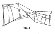
- FIG. 4 shows an example of a surface and the control points that control the surface. As can be seen, only the control points on the four-comers are on the surface. The other control points affect the surface, but are usually not on the surface.
- FIG. 1A is an example of a three-dimensional surface defined by points in a network that is not uniform or of high quality.
- CLASS_A surfaces are typically used in vehicle and consumer goods.
- a car hood is a CLASS_A surface that must be smooth because the smoothness can affect how a potential buyer views the car.
- light reflects off the car hood. If the car hood is smooth and regular, the light reflects in an aesthetically pleasing matter. If the car hood is rough or irregular, the light can reflect in a strange pattern that can negatively affect a potential buyer.
- the present invention as defined by the appended claims relates to a method and system for generating and handling a harmonized network of points. More generally, this invention as defined by the appended claims reorganizes and optimizes a network of points in terms of spatial distribution regularity. Implementations may allow users to manipulate the network of points while maintaining the organization of the network of points.
- a computerized method for manipulating control points is presented.
- the control points form rows along two non-parallel directions U and V.
- This method includes adjusting the position of a control point in an intermediary row in the U direction to provide a smooth transition from the row of control points corresponding to a first edge along the U direction to a row of control points corresponding to a second edge along the U direction.
- the position of the control point is also adjusted in an intermediary row in the V direction to provide a smooth transition from the row of control points corresponding to a first edge along the V direction to a row of control points corresponding to a second edge along the V direction.
- the new position of the control point is computed based on the corresponding adjusted positions of the control point in the intermediary row in the U direction and the control points in the intermediary row in the V direction.
- Implementations may include one or more of the following features.
- the computation of the new position of the control point can include averaging the adjusted position of the control point in the intermediary row in the U direction and the adjusted position of the control point in the intermediary row in the V direction.
- the method can also include determining a reference axis for the first edge along the U direction, the second edge along the U direction, the first edge along the V direction, and the second edge along the V direction.
- a computerized method for manipulating a plurality of control points, the control points forming rows along two non-parallel directions U and V is presented.
- a first row in the U direction is identified corresponding to a control point.
- a determination is made if a row of control points corresponding to a first edge along the U direction and the first row belongs in a first U plane.
- a determination is made if a row of control points corresponding to a second edge along the U direction and the first row belongs in a second U plane.
- the control point is adjusted using the first U plane and the second U plane. The adjustment only occurs if the row of control points corresponding to the first edge along the U direction belongs in the first U plane and the row of control points corresponding to the second edge along the U direction belongs in the second U plane.
- Implementations may include the following features.
- This method can be repeated in the V direction.
- An adjusted U plane can be computed for the control point to provide a smooth transition between the first U plane and the second U plane.
- An adjusted V plane can be computed for the control point to provide a smooth transition between the first V plane and the second V plane.
- the control point can be projected on an intersection of the adjusted U plane and the adjusted V plane.
- the control point can be projected on the adjusted U plane.
- the control point can be projected on the adjusted V plane.
- a computerized method for manipulating a plurality of control points the plurality of control points forming a plurality of rows along two non-parallel directions U and V.
- the method includes identifying a first row in the U direction corresponding to a control point. It is determined if a row of control points corresponding to a first edge along the U direction and the first row belongs in a first U plane. It is determined if a row of control points corresponding to a second edge along the U direction and the first row belongs in a second U plane.
- the control point is constrained using the first U plane and the second U plane, wherein the constraining only occurs if the row of control points corresponding to a first edge along the U direction belongs in the first U plane and the row of control points corresponding to the second edge along the U direction belongs in the second U plane.
- the control points in these methods can define a surface, which can include Béziers surfaces and Nurbs surfaces.
- the surface can be represented in a CAD system.
- the surface can also include a three-dimensional surface.
- the methods described can be implemented in a computer system that includes a computer, which contains a memory, and a processor, and executable software residing in the computer memory. Similarly, the methods can be implemented in a computer data signal embodied in a digital data stream.
- Implementations may include one or more of the following advantages.
- the solution obtained corresponds to the designer's CLASS_A expectations in terms of surface quality received through alignment criteria and positioning of the control points. The times to create and modify the surface can be greatly reduced.
- all the further modifications of the smoothed surface can be done using constrains in order to preserve the homogeneity of the network based on the smoothing defined in the first step.
- the present invention as defined by the appended claims relates to a method and system for generating and handling a harmonized network of points. More generally, this invention as defined by the appended claims reorganizes and optimizes a network of points in terms of spatial distribution regularity. Implementations may allow users to manipulate the network of points while maintaining its organization.
- FIG. 1 presents two examples of the results of the harmonization of the surface using an implementation of this invention.
- FIG. 1A shows a non-uniform surface 100 that is in need of reorganization (i.e., smoothing), and FIG. 1B shows the same surface 110 after applying the harmonization method 120.
- FIG. 1C presents the non-uniform surface 120
- FIG. 1D shows the same surface 120 after applying the harmonization method 130.
- the control point edges (such as edges 101, 111, 121, and 131) on the non-uniform surface 100 and 120 are not changed on the harmonized surface 110 and 130.
- FIG. 2 shows the surface 201 controlled by a network of control points (not shown).
- the two directions of this array are called the U direction 205 and the V direction 206.
- the lines of points forming the edges of this network are called the edges U 202 and the edges V 203.
- the internal lines are called rows 204.
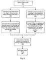
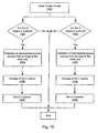
- FIG. 8 presents a flowchart of this arrangement.
- the method starts with an initial surface that needs to be optimized 801, such as FIG. 1A or FIG. 1C.
- a smoothing method is used on the surface 803.
- Local planes are detected to determine whether projections will be applied 802. If local planes are detected 804, then a projection method is applied to further smooth the surface 805.
- the results of this harmonization is an optimized surface 806, such as FIG. 1B or FIG. 1D.
- FIG. 9 presents the smoothing method and FIG. 5 is an illustration of this method.
- the position of the points of the rows are calculated by "sweeping" in the two directions of the network of points along the extreme local axis. As is shown in FIG. 5A, the method sweeps along the V direction 503.
- two local axes 501 and 502, located at the extreme edges and known as the Reference Axes, are computed 902.
- a local axis is defined using X 301, Y 324, and Z 323 axes.
- the origin 302 is taken to be coincident with one of the extreme points of one edge.
- the X direction 301 is defined by the other extremity of the same edge 303.
- Extreme vectors 310 are defined at each extremity of the edge by the extremity point 312 and 313 and its neighbor. The addition of these vectors gives the vector V 311.
- the V direction 311 is adjusted to be orthogonal to the X direction 301 to give the Z direction 323.
- the Y direction results from the vectorial product of the two proceeding directions 324.
- the system takes each U row (for example, 505 and 506), and computes the new position of the points by using the Reference Axis to sweep along the V row 903.
- the extreme points of the rows are not modified.
- Each row is proportionally influenced by the edges depending on its position regarding these edges.
- the changed points can then be stored in the system.
- This smoothing technique can be based on a linear interpolation method, which can allow one edge to influence the control points more than other edges depending on the position of the control points relative to the edge.
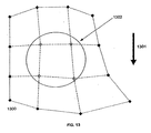
- FIG. 13 presents a simple, two-dimensional four by four network of control points 1300. The method will smooth the points contained in the circle 1302. The extremity points (those outside the circle) will remain unchanged.
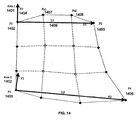
- Axis 1 1401 is defined using the direction of the points P1 1402 and P2 1403.
- the second direction, Y1 1404 is orthogonal to the previous one.
- up and down there are only two possible directions: up and down. Either one can be used, but for this example, the convention of taking the direction that is closest to one of the model axis directions is used. Therefore, up is chosen as the direction for Y1 1404.
- Axis 2 1402 The second axis, Axis 2 1402, is defined the same way, except points P3 1405 and P4 1406 are used.
- the points Pa1 1407 and Pa2 1408 are then expressed in the Axis 1 1401 using a classical transformation from one axis to another. This process is repeated for Axis 2.
- Axis 3 1501 can be defined using the following principle.
- the X3 direction 1502 is computed using the two extreme points P5 1503 and P6 1504.
- the Y3 direction 1505 is computed using Y1 1404 and Y2 1506, and two-coefficients depending on the row index. Equation 1 gives the formula for this calculation.
- Y3 Y1 x C1 + Y2 x C2
- the C1 and C2 coefficients represent the key point for interpolation. These coefficients can be expressed as the influence of the extreme axes on the internal ones. The coefficients are defined using the index of the row according to Equation 3.
- C1 Row / (Number of Rows - 1)
- C2 1 - C1
- the points Pc1 1507 and Pc2 1508 can then be computed using the coordinates of the points Pa1 1407 and Pb1 1408 in their respective axis, two coefficients that depend on the row index, and the length L3 1509 between P5 1503 and P6 1504 as shown in Equation 4.
- Pc1 Pa1 x C1 + Pb1 x C2
- Pc1 x Pc1 x L3
- Equation 4 allows the correct coordinate along X for Pc1 to be computed.
- the final points are obtained using the expression Pc1 and Pc2 in the model axis using a classical transformation from one axis to another. This process can be repeated for Row 2.
- the method also sweeps along the U 512 direction.
- the system first defines the Reference Axes 510 and 512 of the edge V 904. Then, for each V rows (for example 514 and 515), the system computes the new position of the points by sweeping the Reference Axis along edge V 905. The extreme points of the rows are not modified. The changed points can then be stored in the system.
- each row is proportionally influenced by the edges depending on its position regarding these edges.
- the result of this step is smoothed control points 907.
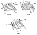
- FIG. 10 presents the local planes detection method and FIG. 6 is an illustration of this method.
- a local plane results if all points of a row are in a same plane.
- the planar detection can be completed using any common methods, such as the least square regression algorithm that determines the median plane.
- the detection of local planes begins with the initial control points of the surface 1001.
- the system determines if each extreme U edge 601 and 602 are along a plane 1002. If they are, the system defines intermediate planes by moving from one edge to the other edge along the U axis 1004. As the system sweeps the U axis 603, the system interpolates and stores the U planes (for example, 604 and 605) 1006.
- the methodology of interpolation can be the same as for the axis interpolation because a plane can be express like an axis (the two directions of the plane and its normal). What can result from this sweep is a set of U planes 1008. If either the first or second extreme U edges are not in a plane, then the system does nothing and no plane is stored.
- the system determines if the extreme V edges are along a plane 1003. If they are, the system defines intermediate planes by moving from one edge to the other edge along the V axis 1005. As it sweeps the V axes, the system interpolates and stores the V planes 1007. What can result from this sweep is a set of V planes 1009. If either the first or second extreme V edges are not in a plane, then the system does nothing and no plane is stored.
- the projection phase is used to improve the result of the smoothing phase according to the local planes, when they exist, by calculating projections on planes or on lines when two planes exist.
- This method begins with the smoothed control points 1101.
- the system determines if there are any U planes 1102. If there are U planes, the system determines if there are any V planes 1103. If there are U planes and V planes, the system projects the points on the line resulting from the intersection of the respective U and V planes 1104. If there are U planes, but no V planes, the system projects the U rows on their respective U planes 1105. If there are V planes, but no U planes, the system projects the V rows on their respective V planes 1107. The movement of each point based on this method will usually be slight.
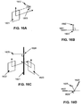
- FIG. 16 presents examples of the two types of projections used in the projection phase.
- the point is projected onto the plane.
- FIG. 16A presents a side view of this projection.
- the original point 1602 is projected onto the plane 1601 using an orthogonal projection, which results in the projected point 1603.
- FIG. 16B shows this same projection from a top view.
- FIG. 16C presents a side view of this projection.
- the original point 1625 is projected onto an intersection line 1621.
- the intersection line is the result of the intersection of the first plane 1622 and the second plane 1623.
- the original point 1625 is projected onto the intersection line 1621 using an orthogonal projection, which results in the projected point 1624.
- FIG. 16D shows this same projection from a top view.
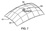
- FIG. 7 shows the results of deforming a surface 701 by "pulling up" on a control point 702. As the control point is raised, the surrounding surface moves with the deformation. This allows the surface to maintain its particular characteristics.
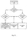
- FIG. 12 presents a flowchart for the deformation method.
- This method uses the control point mesh 1201. Considering a point to modify, this system computes the local planes along the two directions of the mesh. The system determines if the U row is in a plane 1202. If the U row is on a plane, the system then determines if the V row is in a plane 1203. If the U row and the V row are in a plane, the system computes a line resulting from the intersection of the two planes and constraints the point along this line 1207. If the U row is in a plane, but the V row is not in a plane, then the system constrains the point on the detected plane 1206.
- the system constrains the point on the detected plane 1206. If the U row and the V row are not on planes, then the system does not constraint the point 1205, and the translation of the point can be free.
- the determination of planes for this embodiment is the same as for the smoothing method.
- a user-interface for the computing system can be used to allow designers to manipulate and harmonize a network of control points as described above.
Landscapes
- Physics & Mathematics (AREA)
- Engineering & Computer Science (AREA)
- General Physics & Mathematics (AREA)
- Pure & Applied Mathematics (AREA)
- Mathematical Optimization (AREA)
- Mathematical Physics (AREA)
- Mathematical Analysis (AREA)
- Algebra (AREA)
- Computer Graphics (AREA)
- Geometry (AREA)
- Software Systems (AREA)
- Theoretical Computer Science (AREA)
- Processing Or Creating Images (AREA)
- Image Generation (AREA)
- Stored Programmes (AREA)
Claims (16)
- Un procédé informatisé de conception assistée par ordinateur pour le lissage d'un réseau de points de contrôle définissant une surface, le réseau consistant en une pluralité de points de contrôle, la pluralité de points de contrôle formant une pluralité de rangées le long de deux directions non parallèles U et V, et le réseau étant délimité par des rangées formant les bords du réseau, le procédé comprenant :le réglage, dans la direction U, de la position du point de contrôle dans une rangée intermédiaire (514, 515) le long de la direction U (205, 512) pour assurer une transition progressive d'une rangée de points de contrôle correspondant à un premier bord le long de la direction U (205, 512) et une rangée de points de contrôle correspondant à un deuxième bord le long de la direction U (205, 512) ;le réglage, dans la direction V, de la position du point de contrôle dans une rangée intermédiaire (505, 506) le long de la direction V (206, 503) pour assurer une transition progressive entre la rangée de points de contrôle correspondant à un premier bord le long de la direction V (206, 503) et une rangée de points de contrôle correspondant à un deuxième bord le long de la direction V (206, 503) ; etle calcul de la nouvelle position du point de contrôle sur la base des positions réglées correspondantes du point de contrôle dans la rangée intermédiaire (514, 515) le long de la direction U (205, 512) et dans la rangée intermédiaire (505, 506) le long de la direction V (206, 503).
- Le procédé selon la revendication 1, dans lequel le calcul de la nouvelle position comprend en outre le calcul de la moyenne de la position réglée du point de contrôle dans la rangée intermédiaire (514, 515) selon la direction U (205, 512) et de la position réglée du point de contrôle dans la rangée intermédiaire (505, 506) le long de la direction V (206, 503).
- Le procédé selon l'une des revendications 1 ou 2, comprenant en outre :la détermination d'un axe de référence (501, 502, 510, 511) pour le premier bord le long de la direction U (512),du deuxième bord le long de la direction U (512), du premier bord le long de la direction V (503) et du deuxième bord le long de la direction V (503), dans lequel le procédé de détermination de l'axe de référence (501, 502, 510, 511) comprend :pour chaque bord :la détermination d'un vecteur X (301) comprenant un premier point de vecteur situé à une première extrémité (302) du bord et un deuxième point de vecteur situé à une deuxième extrémité (303) du bord ;la détermination d'un vecteur Z (323) comprenant le calcul de la moyenne de deux vecteurs extrêmes orthogonaux (312, 313) réglés par rapport au vecteur X (301) dans lequel les deux vecteurs extrêmes (312, 313) comprennent un vecteur formé par un point d'extrémité et sont voisins ; etla détermination d'un vecteur Y (324) comprenant le produit vectoriel du vecteur X (301) et du vecteur Z (323).
- Le procédé selon la revendication 3, dans lequel le réglage de la position d'un point de contrôle dans une rangée intermédiaire (514, 515) le long de la direction U (205, 512) comprend le réglage du point de contrôle utilisant l'axe de référence (510, 511) pour le premier bord le long de la direction U (205, 512) et pour le deuxième bord le long de la direction U (205, 512) ; et dans lequel le réglage de la position d'un point de contrôle dans une rangée intermédiaire (505, 506) le long de la direction V (206, 503) comprend en outre le réglage du point de contrôle utilisant l'axe de référence (501, 502) pour le premier bord le long de la direction V (206, 503) et pour le deuxième bord le long de la direction V (206, 503).
- Le procédé selon l'une des revendications 1 à 4, comprenant en outre les étapes consistant :à déterminer si une rangée de points de contrôle correspondant à un premier bord (601) le long de la direction U appartient dans un premier plan U ;à déterminer si une rangée de points de contrôle correspondant à un deuxième bord (602) le long de la direction U appartient dans un deuxième plan U ; età régler le point de contrôle utilisant le premier plan U et le deuxième plan U, dans lequel le règlement ne s'effectue que si la rangée de points de contrôle correspondant au premier bord (601) le long de la direction U (603) appartient au premier plan U et si la rangée de points de contrôle correspondant au deuxième bord (602) le long de la direction U appartient au deuxième plan U.
- Le procédé selon la revendication 5, comprenant en outre :le calcul d'un plan U réglé pour le point de contrôle pour assurer une transition progressive entre le premier plan U et le deuxième plan U ; etdans lequel le réglage du point de contrôle utilisant le premier plan U et le deuxième plan U comprend la projection du point de contrôle sur le plan U réglé.
- Le procédé selon l'une des revendications 1 à 4, comprenant en outre les étapes consistant :à déterminer si une rangée de points de contrôle correspondant à un premier bord le long de la direction V appartient dans un premier plan V ;à déterminer si une rangée de points de contrôle correspondant à un deuxième bord le long de la direction V appartient dans un deuxième plan V;età régler le point de contrôle utilisant le premier plan V et le deuxième plan V, dans lesquels le réglage ne s'effectue que dans le cas où la rangée de points de contrôle correspondant au premier bord le long de la direction V appartient dans le premier plan V, et la rangée de points de contrôle correspondant au deuxième bord le long de la direction V appartient dans le deuxième plan V.
- Le procédé selon la revendication 7, comprenant en outre :le calcul d'un plan V réglé pour le point de contrôle pour assurer une transition progressive entre le premier plan V et le deuxième plan V ;dans lequel le réglage du point de contrôle utilisant le premier plan V et le deuxième plan V comprend la projection du point de contrôle sur le plan V réglé.
- Le procédé des revendications 5 et 7, comprenant en outre :le calcul d'un plan U réglé pour le point de contrôle pour assurer une transition progressive entre le premier plan U et le deuxième plan U ; etle calcul d'un plan V réglé pour le point de contrôle pour assurer une transition progressive entre le premier plan V et le deuxième plan V.
- Le procédé selon la revendication 9, dans lequel le réglage du point de contrôle utilisant le premier plan U et le deuxième plan U et le réglage du point de contrôle utilisant le premier plan V et le deuxième plan V comprennent la projection du point de contrôle sur une intersection du plan U réglé et du plan V réglé.
- Le procédé selon l'une des revendications 1 à 10, comprenant en outre l'étape consistant à répéter la première étape de réglage, la deuxième étape de réglage et l'étape de calcul pour chaque point qui n'est pas situé le long du premier bord selon la direction U, le deuxième bord selon la direction U, le troisième bord selon la direction V et le quatrième bord selon la direction V.
- Le procédé selon l'une des revendications 1 à 11, dans lequel la pluralité de points de contrôle définit une surface.
- Le procédé selon la revendication 12, dans lequel la surface comprend une surface choisie dans le groupe consistant en une surface de Bézier et une surface NURBS, dans laquelle la surface est représentée dans un système de CAO.
- Le procédé selon la revendication 12 ou 13, dans lequel la surface comprend une surface tridimensionnelle.
- Un système de conception assistée par ordinateur pour le lissage d'un réseau de points de contrôle définissant une surface, le réseau consistant en une pluralité de points de contrôle, la pluralité de points de contrôle formant une pluralité de rangées le long de deux directions parallèles U et V, et le réseau étant délimité par des rangées formant le bord du réseau, le système comprenant :un ordinateur, dans lequel l'ordinateur comprend une mémoire et un processeur ; etun logiciel exécutable situé dans la mémoire de l'ordinateur dans lequel le logiciel est susceptible de fonctionner avec le processeur afin de :régler, dans la direction U, la position du point de contrôle dans une rangée intermédiaire (514, 515) le long de la direction U (205, 512) pour assurer une transition progressive d'une rangée de points de contrôle correspondant à un premier bord le long de la direction U (205, 512) et une rangée de points de contrôle correspondant à un deuxième bord le long de la direction U (205, 512) ;régler, dans la direction V, la position du point de contrôle dans une rangée intermédiaire (505, 506) le long de la direction V (206, 503) pour assurer une transition progressive entre la rangée de points de contrôle correspondant à un premier bord le long de la direction V (206, 503) et une rangée de points de contrôle correspondant à un deuxième bord le long de la direction V (206, 503) ; etcalculer la nouvelle position du point de contrôle sur la base des positions réglées correspondantes du point de contrôle dans la rangée intermédiaire (514, 515) le long de la direction U (205, 512) et dans la rangée intermédiaire (505, 506) le long de la direction V (206, 503).
- Un signal de données de conception assistée par ordinateur sous la forme d'un flux de données numériques pour le lissage d'un réseau de points de contrôle définissant une surface, le réseau consistant en une pluralité de points de contrôle, la pluralité de points de contrôle formant une pluralité de rangées le long de deux directions non parallèles U et V, le réseau étant délimité par des rangées formant les bords du réseau, le signal comprenant les étapes de :régler, dans la direction U, la position du point de contrôle dans une rangée intermédiaire (514, 515) le long de la direction U (205, 512) pour assurer une transition progressive d'une rangée de points de contrôle correspondant à un premier bord le long de la direction U (205, 512) et une rangée de points de contrôle correspondant à un deuxième bord le long de la direction U (205, 512) ;régler, dans la direction V, la position du point de contrôle dans une rangée intermédiaire (505, 506) le long de la direction V (206, 503) pour assurer une transition progressive entre la rangée de points de contrôle correspondant à un premier bord le long de la direction V (206, 503) et une rangée de points de contrôle correspondant à un deuxième bord le long de la direction V (206, 503) ; etcalculer la nouvelle position du point de contrôle sur la base des positions réglées correspondantes du point de contrôle dans la rangée intermédiaire (514, 515) le long de la direction U (205, 512) et dans la rangée intermédiaire (505, 506) le long de la direction V (206, 503).
Applications Claiming Priority (2)
| Application Number | Priority Date | Filing Date | Title |
|---|---|---|---|
| US788231 | 2001-02-16 | ||
| US09/788,231 US7272541B2 (en) | 2001-02-16 | 2001-02-16 | Method and system for generating and handling a harmonized network of points |
Publications (3)
| Publication Number | Publication Date |
|---|---|
| EP1237125A2 EP1237125A2 (fr) | 2002-09-04 |
| EP1237125A3 EP1237125A3 (fr) | 2004-01-14 |
| EP1237125B1 true EP1237125B1 (fr) | 2005-06-29 |
Family
ID=25143848
Family Applications (1)
| Application Number | Title | Priority Date | Filing Date |
|---|---|---|---|
| EP02290267A Expired - Lifetime EP1237125B1 (fr) | 2001-02-16 | 2002-02-05 | Procédé et système pour la génération et manipulation d'un réseau harmonisé de points |
Country Status (6)
| Country | Link |
|---|---|
| US (1) | US7272541B2 (fr) |
| EP (1) | EP1237125B1 (fr) |
| JP (1) | JP3770840B2 (fr) |
| AT (1) | ATE298911T1 (fr) |
| CA (1) | CA2367774C (fr) |
| DE (1) | DE60204807T2 (fr) |
Families Citing this family (6)
| Publication number | Priority date | Publication date | Assignee | Title |
|---|---|---|---|---|
| US6678575B1 (en) * | 2002-09-13 | 2004-01-13 | General Electric Company | Method and system for generating numerically controlled tool paths on a solid model |
| DE602006002958D1 (de) * | 2006-03-27 | 2008-11-13 | Honda Res Inst Europe Gmbh | Evolutionäre direkte Manipulation von Freiformdeformationsdarstellungen zur Designoptimierung |
| AU2011214895B2 (en) | 2010-02-10 | 2014-12-04 | Thereitis.Com Pty Ltd | Method and system for display of objects in 3D |
| EP3038060B1 (fr) * | 2014-12-23 | 2021-09-15 | Dassault Systèmes | Objet modélisé 3D défini par une grille de points de contrôle |
| EP3051446B1 (fr) | 2015-02-02 | 2025-05-21 | Dassault Systèmes | Gravure d'une image 2d sur une surface à subdivision |
| CN108428230B (zh) * | 2018-03-16 | 2020-06-16 | 青岛海信医疗设备股份有限公司 | 三维虚拟器官中处理曲面的方法、装置、存储介质及设备 |
Family Cites Families (5)
| Publication number | Priority date | Publication date | Assignee | Title |
|---|---|---|---|---|
| US5255352A (en) * | 1989-08-03 | 1993-10-19 | Computer Design, Inc. | Mapping of two-dimensional surface detail on three-dimensional surfaces |
| US5510995A (en) * | 1993-08-13 | 1996-04-23 | Iowa State University Research Foundation, Inc. | Sculptured surface synthesis based on functional design constraints |
| JPH07282117A (ja) * | 1994-04-08 | 1995-10-27 | Ricoh Co Ltd | 自由曲面生成方法及び自由曲面形状の制御方法 |
| US6016487A (en) * | 1997-03-26 | 2000-01-18 | National Research Council Of Canada | Method of searching three-dimensional images |
| US7196702B1 (en) * | 1998-07-23 | 2007-03-27 | Freedesign, Inc. | Geometric design and modeling system using control geometry |
-
2001
- 2001-02-16 US US09/788,231 patent/US7272541B2/en not_active Expired - Lifetime
-
2002
- 2002-01-15 CA CA002367774A patent/CA2367774C/fr not_active Expired - Lifetime
- 2002-02-05 DE DE60204807T patent/DE60204807T2/de not_active Expired - Lifetime
- 2002-02-05 EP EP02290267A patent/EP1237125B1/fr not_active Expired - Lifetime
- 2002-02-05 AT AT02290267T patent/ATE298911T1/de not_active IP Right Cessation
- 2002-02-18 JP JP2002040561A patent/JP3770840B2/ja not_active Expired - Lifetime
Also Published As
| Publication number | Publication date |
|---|---|
| JP3770840B2 (ja) | 2006-04-26 |
| US7272541B2 (en) | 2007-09-18 |
| JP2002288244A (ja) | 2002-10-04 |
| DE60204807D1 (de) | 2005-08-04 |
| CA2367774C (fr) | 2009-10-13 |
| EP1237125A3 (fr) | 2004-01-14 |
| CA2367774A1 (fr) | 2002-08-16 |
| ATE298911T1 (de) | 2005-07-15 |
| US20050055182A1 (en) | 2005-03-10 |
| EP1237125A2 (fr) | 2002-09-04 |
| DE60204807T2 (de) | 2006-05-04 |
Similar Documents
| Publication | Publication Date | Title |
|---|---|---|
| US7212205B2 (en) | Curved surface image processing apparatus and curved surface image processing method | |
| US6356263B2 (en) | Adaptive subdivision of mesh models | |
| Duchaineau et al. | ROAMing terrain: Real-time optimally adapting meshes | |
| Von Herzen et al. | Accurate triangulations of deformed, intersecting surfaces | |
| EP1026639A2 (fr) | Appareil et procédé de traitement d'images tridimensionnelles | |
| CN115861547A (zh) | 一种基于投影的模型表面样条线生成方法 | |
| US6603473B1 (en) | Detail data pertaining to the shape of an object surface and related methods and systems | |
| US20080084414A1 (en) | Method for Creating a Parametric Surface Symmetric With Respect to a Given Symmetry Operation | |
| JP2001052196A (ja) | 文字枠により囲まれた距離フィールドのディテール指向型階層表現を生成する方法及びデータを記憶するメモリ | |
| WO2000002165A1 (fr) | Procede permettant de produire des donnees de polygone et afficheur d'images utilisant lesdites donnees | |
| JP2001052206A (ja) | モデルとして表現されるオブジェクトを彫塑する方法 | |
| JP2001052209A (ja) | 色階調をディテール指向型階層距離フィールドとして表す方法 | |
| US8793108B2 (en) | Three-dimensional model determination from two-dimensional sketch with two-dimensional refinement | |
| JP2007265401A (ja) | デザイン最適化のための自由形状変形(FreeFormDeformation)表現の進化的直接操作(EvolutionaryDirectManipulation) | |
| EP1097435B1 (fr) | Evaluation parametrique de surfaces dans un espace vrai de matrice de subdivision d'un carreau irregulier | |
| US7023435B1 (en) | Object surface representation and related methods and systems | |
| US6693631B2 (en) | System and method for multi-resolution fairing of non-manifold models | |
| EP1237125B1 (fr) | Procédé et système pour la génération et manipulation d'un réseau harmonisé de points | |
| Ruprecht et al. | Deformed cross‐dissolves for image interpolation in scientific visualization | |
| JP3593155B2 (ja) | 形状設計支援装置 | |
| CN119720305A (zh) | 用于通过使用部分草图来修改3d模型的方法 | |
| US6920415B1 (en) | Method of trimming a representation of an object surface comprising a mesh of tessellated polygons and related system | |
| Yasui et al. | Surface quality assessment of subdivision surfaces on programmable graphics hardware | |
| US6941251B1 (en) | Method for transforming CAD model using general function composition mechanism | |
| Mullineux | Improvement of free-form surfaces for product styling applications |
Legal Events
| Date | Code | Title | Description |
|---|---|---|---|
| PUAI | Public reference made under article 153(3) epc to a published international application that has entered the european phase |
Free format text: ORIGINAL CODE: 0009012 |
|
| AK | Designated contracting states |
Kind code of ref document: A2 Designated state(s): AT BE CH CY DE DK ES FI FR GB GR IE IT LI LU MC NL PT SE TR |
|
| AX | Request for extension of the european patent |
Free format text: AL;LT;LV;MK;RO;SI |
|
| PUAL | Search report despatched |
Free format text: ORIGINAL CODE: 0009013 |
|
| AK | Designated contracting states |
Kind code of ref document: A3 Designated state(s): AT BE CH CY DE DK ES FI FR GB GR IE IT LI LU MC NL PT SE TR |
|
| AX | Request for extension of the european patent |
Extension state: AL LT LV MK RO SI |
|
| RIC1 | Information provided on ipc code assigned before grant |
Ipc: 7G 06T 17/20 A Ipc: 7G 06T 17/30 B |
|
| 17P | Request for examination filed |
Effective date: 20040305 |
|
| 17Q | First examination report despatched |
Effective date: 20040420 |
|
| AKX | Designation fees paid |
Designated state(s): AT BE CH CY DE DK ES FI FR GB GR IE IT LI LU MC NL PT SE TR |
|
| GRAP | Despatch of communication of intention to grant a patent |
Free format text: ORIGINAL CODE: EPIDOSNIGR1 |
|
| GRAS | Grant fee paid |
Free format text: ORIGINAL CODE: EPIDOSNIGR3 |
|
| GRAA | (expected) grant |
Free format text: ORIGINAL CODE: 0009210 |
|
| AK | Designated contracting states |
Kind code of ref document: B1 Designated state(s): AT BE CH CY DE DK ES FI FR GB GR IE IT LI LU MC NL PT SE TR |
|
| PG25 | Lapsed in a contracting state [announced via postgrant information from national office to epo] |
Ref country code: AT Free format text: LAPSE BECAUSE OF FAILURE TO SUBMIT A TRANSLATION OF THE DESCRIPTION OR TO PAY THE FEE WITHIN THE PRESCRIBED TIME-LIMIT Effective date: 20050629 Ref country code: NL Free format text: LAPSE BECAUSE OF FAILURE TO SUBMIT A TRANSLATION OF THE DESCRIPTION OR TO PAY THE FEE WITHIN THE PRESCRIBED TIME-LIMIT Effective date: 20050629 Ref country code: CH Free format text: LAPSE BECAUSE OF FAILURE TO SUBMIT A TRANSLATION OF THE DESCRIPTION OR TO PAY THE FEE WITHIN THE PRESCRIBED TIME-LIMIT Effective date: 20050629 Ref country code: FI Free format text: LAPSE BECAUSE OF FAILURE TO SUBMIT A TRANSLATION OF THE DESCRIPTION OR TO PAY THE FEE WITHIN THE PRESCRIBED TIME-LIMIT Effective date: 20050629 Ref country code: IT Free format text: LAPSE BECAUSE OF FAILURE TO SUBMIT A TRANSLATION OF THE DESCRIPTION OR TO PAY THE FEE WITHIN THE PRESCRIBED TIME-LIMIT;WARNING: LAPSES OF ITALIAN PATENTS WITH EFFECTIVE DATE BEFORE 2007 MAY HAVE OCCURRED AT ANY TIME BEFORE 2007. THE CORRECT EFFECTIVE DATE MAY BE DIFFERENT FROM THE ONE RECORDED. Effective date: 20050629 Ref country code: BE Free format text: LAPSE BECAUSE OF FAILURE TO SUBMIT A TRANSLATION OF THE DESCRIPTION OR TO PAY THE FEE WITHIN THE PRESCRIBED TIME-LIMIT Effective date: 20050629 Ref country code: LI Free format text: LAPSE BECAUSE OF FAILURE TO SUBMIT A TRANSLATION OF THE DESCRIPTION OR TO PAY THE FEE WITHIN THE PRESCRIBED TIME-LIMIT Effective date: 20050629 |
|
| REG | Reference to a national code |
Ref country code: GB Ref legal event code: FG4D |
|
| REG | Reference to a national code |
Ref country code: CH Ref legal event code: EP |
|
| REF | Corresponds to: |
Ref document number: 60204807 Country of ref document: DE Date of ref document: 20050804 Kind code of ref document: P |
|
| REG | Reference to a national code |
Ref country code: IE Ref legal event code: FG4D |
|
| PG25 | Lapsed in a contracting state [announced via postgrant information from national office to epo] |
Ref country code: GR Free format text: LAPSE BECAUSE OF FAILURE TO SUBMIT A TRANSLATION OF THE DESCRIPTION OR TO PAY THE FEE WITHIN THE PRESCRIBED TIME-LIMIT Effective date: 20050929 Ref country code: DK Free format text: LAPSE BECAUSE OF FAILURE TO SUBMIT A TRANSLATION OF THE DESCRIPTION OR TO PAY THE FEE WITHIN THE PRESCRIBED TIME-LIMIT Effective date: 20050929 Ref country code: SE Free format text: LAPSE BECAUSE OF FAILURE TO SUBMIT A TRANSLATION OF THE DESCRIPTION OR TO PAY THE FEE WITHIN THE PRESCRIBED TIME-LIMIT Effective date: 20050929 |
|
| NLV1 | Nl: lapsed or annulled due to failure to fulfill the requirements of art. 29p and 29m of the patents act | ||
| PG25 | Lapsed in a contracting state [announced via postgrant information from national office to epo] |
Ref country code: PT Free format text: LAPSE BECAUSE OF FAILURE TO SUBMIT A TRANSLATION OF THE DESCRIPTION OR TO PAY THE FEE WITHIN THE PRESCRIBED TIME-LIMIT Effective date: 20051207 |
|
| REG | Reference to a national code |
Ref country code: CH Ref legal event code: PL |
|
| PG25 | Lapsed in a contracting state [announced via postgrant information from national office to epo] |
Ref country code: IE Free format text: LAPSE BECAUSE OF NON-PAYMENT OF DUE FEES Effective date: 20060206 |
|
| PG25 | Lapsed in a contracting state [announced via postgrant information from national office to epo] |
Ref country code: LU Free format text: LAPSE BECAUSE OF NON-PAYMENT OF DUE FEES Effective date: 20060228 Ref country code: MC Free format text: LAPSE BECAUSE OF NON-PAYMENT OF DUE FEES Effective date: 20060228 |
|
| ET | Fr: translation filed | ||
| PLBE | No opposition filed within time limit |
Free format text: ORIGINAL CODE: 0009261 |
|
| STAA | Information on the status of an ep patent application or granted ep patent |
Free format text: STATUS: NO OPPOSITION FILED WITHIN TIME LIMIT |
|
| 26N | No opposition filed |
Effective date: 20060330 |
|
| REG | Reference to a national code |
Ref country code: IE Ref legal event code: MM4A |
|
| PG25 | Lapsed in a contracting state [announced via postgrant information from national office to epo] |
Ref country code: TR Free format text: LAPSE BECAUSE OF FAILURE TO SUBMIT A TRANSLATION OF THE DESCRIPTION OR TO PAY THE FEE WITHIN THE PRESCRIBED TIME-LIMIT Effective date: 20050629 |
|
| PG25 | Lapsed in a contracting state [announced via postgrant information from national office to epo] |
Ref country code: CY Free format text: LAPSE BECAUSE OF FAILURE TO SUBMIT A TRANSLATION OF THE DESCRIPTION OR TO PAY THE FEE WITHIN THE PRESCRIBED TIME-LIMIT Effective date: 20050629 |
|
| PG25 | Lapsed in a contracting state [announced via postgrant information from national office to epo] |
Ref country code: ES Free format text: LAPSE BECAUSE OF NON-PAYMENT OF DUE FEES Effective date: 20060228 |
|
| REG | Reference to a national code |
Ref country code: FR Ref legal event code: PLFP Year of fee payment: 15 |
|
| REG | Reference to a national code |
Ref country code: FR Ref legal event code: PLFP Year of fee payment: 16 |
|
| REG | Reference to a national code |
Ref country code: FR Ref legal event code: PLFP Year of fee payment: 17 |
|
| PGFP | Annual fee paid to national office [announced via postgrant information from national office to epo] |
Ref country code: FR Payment date: 20210224 Year of fee payment: 20 |
|
| PGFP | Annual fee paid to national office [announced via postgrant information from national office to epo] |
Ref country code: GB Payment date: 20210219 Year of fee payment: 20 Ref country code: DE Payment date: 20210217 Year of fee payment: 20 |
|
| REG | Reference to a national code |
Ref country code: DE Ref legal event code: R071 Ref document number: 60204807 Country of ref document: DE |
|
| REG | Reference to a national code |
Ref country code: GB Ref legal event code: PE20 Expiry date: 20220204 |
|
| PG25 | Lapsed in a contracting state [announced via postgrant information from national office to epo] |
Ref country code: GB Free format text: LAPSE BECAUSE OF EXPIRATION OF PROTECTION Effective date: 20220204 |
|
| P01 | Opt-out of the competence of the unified patent court (upc) registered |
Effective date: 20230527 |