EP1236904A2 - Compresseur à palettes - Google Patents
Compresseur à palettes Download PDFInfo
- Publication number
- EP1236904A2 EP1236904A2 EP02251386A EP02251386A EP1236904A2 EP 1236904 A2 EP1236904 A2 EP 1236904A2 EP 02251386 A EP02251386 A EP 02251386A EP 02251386 A EP02251386 A EP 02251386A EP 1236904 A2 EP1236904 A2 EP 1236904A2
- Authority
- EP
- European Patent Office
- Prior art keywords
- pressure
- groove
- communication passage
- valve body
- scoop
- Prior art date
- Legal status (The legal status is an assumption and is not a legal conclusion. Google has not performed a legal analysis and makes no representation as to the accuracy of the status listed.)
- Granted
Links
Images


Classifications
-
- F—MECHANICAL ENGINEERING; LIGHTING; HEATING; WEAPONS; BLASTING
- F04—POSITIVE - DISPLACEMENT MACHINES FOR LIQUIDS; PUMPS FOR LIQUIDS OR ELASTIC FLUIDS
- F04C—ROTARY-PISTON, OR OSCILLATING-PISTON, POSITIVE-DISPLACEMENT MACHINES FOR LIQUIDS; ROTARY-PISTON, OR OSCILLATING-PISTON, POSITIVE-DISPLACEMENT PUMPS
- F04C28/00—Control of, monitoring of, or safety arrangements for, pumps or pumping installations specially adapted for elastic fluids
- F04C28/28—Safety arrangements; Monitoring
-
- F—MECHANICAL ENGINEERING; LIGHTING; HEATING; WEAPONS; BLASTING
- F01—MACHINES OR ENGINES IN GENERAL; ENGINE PLANTS IN GENERAL; STEAM ENGINES
- F01C—ROTARY-PISTON OR OSCILLATING-PISTON MACHINES OR ENGINES
- F01C21/00—Component parts, details or accessories not provided for in groups F01C1/00 - F01C20/00
- F01C21/08—Rotary pistons
- F01C21/0809—Construction of vanes or vane holders
- F01C21/0818—Vane tracking; control therefor
- F01C21/0854—Vane tracking; control therefor by fluid means
- F01C21/0863—Vane tracking; control therefor by fluid means the fluid being the working fluid
-
- F—MECHANICAL ENGINEERING; LIGHTING; HEATING; WEAPONS; BLASTING
- F04—POSITIVE - DISPLACEMENT MACHINES FOR LIQUIDS; PUMPS FOR LIQUIDS OR ELASTIC FLUIDS
- F04C—ROTARY-PISTON, OR OSCILLATING-PISTON, POSITIVE-DISPLACEMENT MACHINES FOR LIQUIDS; ROTARY-PISTON, OR OSCILLATING-PISTON, POSITIVE-DISPLACEMENT PUMPS
- F04C18/00—Rotary-piston pumps specially adapted for elastic fluids
- F04C18/30—Rotary-piston pumps specially adapted for elastic fluids having the characteristics covered by two or more of groups F04C18/02, F04C18/08, F04C18/22, F04C18/24, F04C18/48, or having the characteristics covered by one of these groups together with some other type of movement between co-operating members
- F04C18/34—Rotary-piston pumps specially adapted for elastic fluids having the characteristics covered by two or more of groups F04C18/02, F04C18/08, F04C18/22, F04C18/24, F04C18/48, or having the characteristics covered by one of these groups together with some other type of movement between co-operating members having the movement defined in group F04C18/08 or F04C18/22 and relative reciprocation between the co-operating members
- F04C18/344—Rotary-piston pumps specially adapted for elastic fluids having the characteristics covered by two or more of groups F04C18/02, F04C18/08, F04C18/22, F04C18/24, F04C18/48, or having the characteristics covered by one of these groups together with some other type of movement between co-operating members having the movement defined in group F04C18/08 or F04C18/22 and relative reciprocation between the co-operating members with vanes reciprocating with respect to the inner member
- F04C18/3446—Rotary-piston pumps specially adapted for elastic fluids having the characteristics covered by two or more of groups F04C18/02, F04C18/08, F04C18/22, F04C18/24, F04C18/48, or having the characteristics covered by one of these groups together with some other type of movement between co-operating members having the movement defined in group F04C18/08 or F04C18/22 and relative reciprocation between the co-operating members with vanes reciprocating with respect to the inner member the inner and outer member being in contact along more than one line or surface
-
- F—MECHANICAL ENGINEERING; LIGHTING; HEATING; WEAPONS; BLASTING
- F04—POSITIVE - DISPLACEMENT MACHINES FOR LIQUIDS; PUMPS FOR LIQUIDS OR ELASTIC FLUIDS
- F04C—ROTARY-PISTON, OR OSCILLATING-PISTON, POSITIVE-DISPLACEMENT MACHINES FOR LIQUIDS; ROTARY-PISTON, OR OSCILLATING-PISTON, POSITIVE-DISPLACEMENT PUMPS
- F04C28/00—Control of, monitoring of, or safety arrangements for, pumps or pumping installations specially adapted for elastic fluids
- F04C28/06—Control of, monitoring of, or safety arrangements for, pumps or pumping installations specially adapted for elastic fluids specially adapted for stopping, starting, idling or no-load operation
Definitions
- the present invention relates to a gas compressor of a vane rotary type for use in a car air conditioner system, and more particularly to a gas compressor in which vane back pressure can be reduced without degrading projectability of the vanes upon starting operation of the compressor.
- a gas compressor of such a vane rotary type in a gas compressor of such a vane rotary type, the interior of a cylinder 4 is partitioned into a plurality of small chambers by being defined by the cylinder 4, side blocks 5 and 6, a rotor 7, and vanes 12.
- Each of the thus partitioned small chambers functions as a compress ion chamber 13 for executing compression of a refrigerant gas.
- each compression chamber 13 alternately increases and decreases as the rotor 7 rotates, and a refrigerant gas in a suction chamber 14 is sucked up and compressed due to the variations in the volume and then discharged into a discharge chamber 15 side.
- the vanes 12 slide within a vane groove 11 of the rotor 7 and is projected from the outer peripheral surface of the rotor 7 toward the inner peripheral surface of the cylinder 4.
- oil having a pressure lower than a discharge pressure Pd of the refrigerant gas is supplied as vane back pressure from scoop grooves 22, 23 of the front-side side block 5 and the rear-side side block 6 into the bottom portion of the vane groove 11. Then, the vanes 12 is pushed onto the inner peripheral surface of the cylinder 4 due to this vane back pressure and a centrifugal force generated by the rotation of the rotor 7.
- the pressure in the compression chamber 13 increases due to the pressure of the compressed refrigerant gas, and the increased pressure acts to push back the vanes 12 into the vane groove 11 so that the vanes 12 are moved away from the inner peripheral surface of the cylinder 4.
- the bottom portion of the vane groove 11 communicates with a high pressure supply hole 24 of the rear-side side block 6 at a time immediately before the discharge of the refrigerant gas, and then high-pressure oil having a pressure equivalent to the discharge pressure Pd is supplied as vane back pressure from the high pressure supply hole 24 into the bottom portion of the vane groove 11.
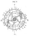
- the scoop grooves 22, 23 and the high pressure supply hole 24 are arranged separately from each other, as shown in Fig. 12, the scoop grooves 22, 23 and the high pressure supply hole 24 are communicated with each other via the vane groove 11 during the time when the vane groove 11 moves apart from the scoop grooves 22, 23 toward the high pressure supply hole 24 side.
- high-pressure oil flows into the scoop grooves 22, 23 side from the high pressure supply hole 24 via the vane groove 11, and the oil pressures within the scoop grooves 22, 23 are thus likely to increase. Therefore, the vane back pressure can readily rise upon starting the operation of the compressor, and the projectability of the vanes 12 is thus improved.
- the vane back pressure becomes excessively high, which results in such problems that not only is abrasion of the vanes 12 increased but also the power required for operating the compressor is increased.
- the present invention has been made in view of the above problems , and therefore an object thereof is to provide a gas compressor in which power saving as well as improved compression performance and durability are attained by enabling reduction of the vane back pressure without degrading the projectability of the vanes upon starting the operation of the compressor.
- a gas compressor comprising: a cylinder having side blocks attached to its end surface; a rotor rotatably disposed within the cylinder; vanes which slide within a vane groove that is formed on an outer peripheral surface of the rotor and which is arranged so as to be projectable from an outer peripheral surface of the rotor toward an inner peripheral surface of the cylinder; a compression chamber constituted by a small chamber that is partitioned off and defined in the interior of the cylinder by the cylinder, the side blocks, the rotor, and the vanes, which alternately increases and decreases in volume as the rotor rotates, and sucks in and compress a refrigerant gas in a low-pressure chamber due to the volume variation and then discharges it into a high-pressure chamber side; a scoop groove with which a bottom portion of the vane groove communicates during a suction and compression process of the coolant gas, and from which a vane back pressure is supplied into the bottom
- the vane groove is communicated with neither of the scoop groove and the high pressure supply hole during the time when it moves apart from the scoop groove toward the high pressure supply hole.
- the pressure control valve is actuated to introduce a relatively high pressure gas from the low-pressure chamber into the scoop groove side through the communication passage, thereby attaining an effect that the pressure within the scoop groove and the vane back pressure can readily rise upon starting the operation of the compressor.
- the pressure control valve includes: a communication passage communicating the suction chamber with the scoop groove; a hole having a shape of a circular truncated cone, which is arranged as a valve seat portion on a way of the communication passage; a valve body which is movably disposed within the communication passage and which is formed such that it may be fitted into the hole having a shape of a circular truncated cone; and a width extending means for partially extending a width of a minute gap between the valve body and the communication passage, in which when the pressure in the suction chamber has become higher than the pressure in the scoop groove, the valve body is moved apart from the hole having a shape of a circular truncated cone due to a pressure difference to thereby set the communication passage in an opened state, whereas when the pressure in the scoop groove has risen to exceed the pressure in the suction chamber, the valve body is pushed back into close contact with the hole having a shape of a
- the pressure control valve includes: a communication passage communicating the suction chamber with the scoop groove; a hole having a shape of a circular truncated cone, which is arranged as a valve seat portion on a way of the communication passage; a valve body which is movably arranged within the communication passage and which is formed such that it may be fitted into the hole having a shape of a circular truncated cone; and a biasing means that constantly biases the valve body in a direction to move the valve body away from the hole having a shape of the circular truncated cone, in which when the pressure in the suction chamber becomes higher than the pressure in the scoop groove, the valve body is moved apart from the hole having a shape of a circular truncated cone due to a pressure difference to thereby set the communication passage in an opened state, whereas when the pressure in the scoop groove has risen to exceed the pressure in the suction chamber, the valve body is pushed back into close contact with the hole having
- the pressure control valve includes: a communication passage communicating the suction chamber with the scoop groove; a hole having a shape of a circular truncated cone, which is arranged as a valve seat portion on a way of the communication passage; a valve body which is movably arranged within the communication passage and which is formed such that it may be fitted into the hole having a shape of a circular truncated cone; a width extending means for partially extending a width of a minute gap between the valve body and the communication passage; and a biasing means that constantly biases the valve body in a direction to move the valve body away from the hole having a shape of the circular truncated cone, in which when the pressure in the suction chamber becomes higher than the pressure in the scoop groove, the valve body is moved apart from the hole having a shape of a circular truncated cone due to a pressure difference to thereby set the communication passage in an opened state, whereas when the pressure in the scoop groove
- the width extending means 1) means for extending the width of the minute gap in an upper region thereof, out of the entire area of the minute gap; 2) means for extending the width of the minute gap at several locations; 3 ) a groove formed on an inner wall of the communication passage along a direction of movement of the valve body; 4) a groove formed on an outer peripheral surface of the valve body; and so on.
- a biasing force applied by the biasing means may be set to be greater than an adhesive force of an oil film to adhere the valve body to the hole having a shape of a circular truncated cone.
- the gas compressor of the present embodiment has a structure in which, as shown in Fig. 1, a compression mechanism portion 2 is accommodated in a compressor case 1 having one open end, and a front head 3 is attached to the one open end of the compressor case 1.
- the compression mechanism portion 2 includes a cylinder 4 whose inner periphery is elliptical, and side blocks 5 and 6 are attached to both end surfaces of the cylinder 4. Also, a rotor 7 is disposed within the cylinder 4. The rotor 7 is rotatably disposed therein by means of a rotor shaft 8 that is provided integrally with an axial center thereof, and bearings 9 and 10 of the side blocks 5 and 6 which support the rotor shaft 8.
- slit-like vane grooves 11 are cut out on the outer peripheral surface of the rotor 7 and vanes 12 are fitted in each of these vane grooves 11.
- Each of the vanes 12 slides within the vane groove 11 and is disposed in such a way as to project from the outer peripheral surface of the rotor 7 toward an inner peripheral surface of the cylinder 4.
- the interior of the cylinder 4 is partitioned into a plurality of small chambers each being defined by an inner wall of the cylinder 4, inner surfaces of the side blocks 5 and 6, the outer peripheral surface of the rotor 7 and both side surfaces on the tip end side of the vanes 12.
- Each of the thus partitioned small chambers constitutes a compression chamber 13.
- the volume of the compression chamber 13 alternately increases and decreases as the rotor 7 rotates in a direction indicated by an arrow in the drawing.
- Refrigerant gas in a suction chamber 14, which is a low-pressure chamber is thus sucked in due to the volume variations to be compressed and discharged into a discharge chamber 15 side as a high-pressure chamber.
- a reed valve 17 of a cylinder discharge hole 16 that is located near short diameter portion of the cylinder ellipse is opened due to the pressure of the compressed high-pressure refrigerant gas.
- the high-pressure refrigerant gas within the compression chamber 13 is discharged into a discharge chamber 18 formed in the outside of the cylinder through the cylinder discharge hole 16, and is further introduced to the discharge chamber 15 side from the discharge chamber 18 via an oil separator 19 and the like.
- Oil used for lubrication and the like is contained in a form of mist within the high-pressure refrigerant gas discharged into the discharge chamber 18. Such oil components of the high-pressure refrigerant gas are separated and captured when the refrigerant gas passes through the oil separator 19, and are dropped onto an oil pool 20 located at the bottom portion of the discharge chamber 15 and pooled therein.
- the pressure of the high-pressure refrigerant gas that is discharged into the discharge chamber 15 acts on the oil pool 20 described above, so that oil reserved in the oil pool 20 on which this discharge pressure Pd acts is forcedly supplied to the rear-side bearing 10 through an oil hole 21 formed in the rear-side side block 6. Then, the oil is decompressed upon passage of the clearance of the bearing 10, and the decompressed oil flows into a rear-side scoop groove 23 to be supplied therefrom. Further, due to the pressure acting thereupon, the oil in the oil pool 20 is also forcedly supplied to the front-side bearing 9 through an oil hole 21 formed in the cylinder 4 and an oil hole 21 formed in the front-side side block 5. Then, the oil is decompressed upon passage of the clearance of the bearing 9, and the decompressed oil flows into a front-side scoop groove 22 to be supplied therefrom.
- the rear-side scoop groove 23 is formed on a surface of the rear-side side block 6 which opposes the cylinder, whereas the front-side scoop groove 22 is formed on a surface of the front-side side block 5 which opposes the cylinder. Further, these two scoop grooves 22, 23 are both formed so as to oppose and communicate with a bottom portion of the vane groove 11 during suction and compression of the refrigerant gas. While the bottom portion of the vane groove 11 and the scoop grooves 22,23 are thus being communicated with each other, low-pressure oil is supplied from the scoop grooves 22,23 into the bottom portion of the vane groove 11 as back pressure. Note that, in this embodiment, the shape of the scoop grooves 22,23 formed is a sector.
- the bottom portion of the vane groove 11 communicates with the scoop grooves 22,23 within an angular range of from ⁇ 1 to ⁇ 2 , with ⁇ 1 being an angle at which a spread of the sector starts (scoop groove starting angle) and ⁇ 2 being an angle at which the spread of the sector ends (scoop groove ending angle).
- a high pressure supply hole 24 is formed on a surface of the rear-side side block 6 which opposes the cylinder.
- the high pressure supply hole 24 is formed such that it communicates with a bottom portion of the vane groove 11 at a time immediately before discharge of the high-pressure refrigerant gas. While the bottom portion of the vane groove 11 and the high pressure supply hole 24 are thus being communicated with each other, oil having a higher pressure than that supplied to the scoop grooves 22,23 is supplied from the high pressure supply hole 24 into the bottom portion of the vane groove 11 as vane back pressure.
- oil having a pressure higher than that supplied from the scoop grooves 22, 23 oil having a pressure equivalent to the discharge pressure Pd is used.
- This oil having a pressure equivalent to the discharge pressure Pd is adapted to be introduced directly to the high pressure supply hole 24 from the oil hole 21 of the read-side side block 6 without passing through clearance of the bearing 10.
- the scoop grooves 22, 23 and the high pressure supply hole 24 are disposed independently and separately while being spaced apart from each other.
- the space therebetween is set to an interval sufficient to ensure that the vane groove 11 is communicated with neither the scoop grooves 22, 23 nor the high pressure supply hole 24 while the vane groove 11 moves apart from the scoop grooves 22, 23 toward the high pressure supply hole 24, that is, while the suction and compression process of the refrigerant gas is being shifted to the discharge process.
- the vane groove 11 moves apart from the scoop grooves 22, 23 toward the high pressure supply hole 24, the vane groove 11 is communicated with neither the scoop grooves 22, 23 nor the high pressure supply hole 24. Therefore, it is possible to obviate the risk that high-pressure oil, that is, oil having a pressure equivalent to the discharge pressure Pd, flows from the high pressure supply hole 24 side into the scoop grooves 22, 23 side through the vane groove 11 during a steady operation of the compressor, which in turn prevents oil pressure within the scoop grooves from rising due to the high-pressure oil thus flowing thereto and a resulting increase of the vane back pressure. Also, abrasion of the vanes 12 is lessened and power required for operating the gas compressor can be reduced as well.
- high-pressure oil that is, oil having a pressure equivalent to the discharge pressure Pd
- the non-interconnecting structure such as described above
- the stopped position of the vane groove 11 at least one of five upon stopping the operation of the gas compressor is located between the scoop groove 22 and the high pressure supply hole 24 as shown in Fig. 2
- the bottom portion of the vane groove 11 is communicated with neither the scoop groove 22 nor the high pressure supply hole 24. Therefore, the vane back pressure at the bottom portion of the vane groove 11 can be maintained at a relatively high level during the stoppage of the gas compressor operation, and projectability of the vanes 12 upon restarting the operation of the gas compressor can be also improved.
- the projectability of the vanes 12 is particularly degraded if there exists a reversed relationship among the pressures in the suction chamber 14 (low-pressure chamber), the discharge chamber 15 (high-pressure chamber), and the scoop grooves 22,23, that is, if the pressure in the suction chamber 14 has become higher than those in the discharge chamber 15 (high-pressure chamber) and the scoop grooves 22, 23.
- a pressure control valve 50 is provided in the gas compressor according to this embodiment, as shown in Fig. 1.
- the pressure control valve 50 shown in Fig. 1 includes a communication passage 51 communicating the suction chamber 14 with the scoop groove 22 with each other, and a hole 52 having a shape of a circular truncated cone is arranged on a way of the communication passage 51 as a valve seat portion.
- the hole 52 having a shape of a circular truncated cone is formed such that, of both open ends thereof, a small-diameter open end 52a on the top portion side of the circular truncated cone is communicated with the suction chamber 14 side, and a large-diameter open end 52b on the bottom portion side of the circular truncated cone is communicated with the scoop groove 22 side.
- the communication passage 51 there may be conceived various means for forming the communication passage 51 described above; in the pressure control valve 50 of this embodiment, a structure is adopted such that, in a through hole 53 piercing from the suction chamber 14 to the scoop groove 22, a cylindrical bush 54 having a length substantially equal to that of the through hole 53 is disposed and the entirety of a cylinder hollow hole 54a of the cylindrical bush 54 is used as the communication passage 51.
- the cylinder hollow hole 54a is divided into two parts, namely a large-diameter hole 54a-1 constituting a part thereof, and a small-diameter hole 54a-2 constituting the front portion thereof located past the area of the large-diameter hole 54a-1.
- the hole 52 having a shape of a circular truncated cone is formed at the bottom portion of the large-diameter hole 54a-1 and a valve body 55 having a shape of a steel ball, such as a ball valve, is movably received in the large-diameter hole 54a-1.
- the pressure control valve 50 shown in Fig. 3 having the structure described above is actuated when there exists the aforementioned reversed pressure relationship at the time of starting the operation of the compressor.
- the pressure control valve 50 is actuated, the scoop groove 23 and the suction chamber 14 are communicated with each other only at the time of starting the operation of the compressor.
- the pressure control valve 50 is actuated to allow a relatively high pressure to be introduced from the suction chamber 14 into the scoop groove 23 side via a communication passage 26. Therefore, the pressure in the scoop groove 23 and the vane back pressure can readily rise, thereby attaining improved projectability of the vanes 12 at the time of starting the operation of the compressor.
- Fig. 4 illustrates results of a comparison test between the vane back pressure in the gas compressor of the present invention (apparatus of the present invention) and that in the conventional gas compressor (conventional apparatus) shown in Fig. 10. As is apparent from the results of the comparison test, it has been found that the vane back pressure can be reduced in the apparatus of the present invention as compared with the conventional apparatus.
- a pressure control valve 50 shown in Figs. 5A 5B may also be employed instead of the pressure control valve 50 shown in Fig. 3.
- a minute gap G having a size that is at least required to allow movement of the valve body 55 is formed between the valve body 55 and the communication passage 51 in each of the pressure control valves 50 shown in Fig. 3 and Figs. 5A 5B
- the pressure control valve 50 of Figs. 5A 5B is different from the pressure control valve 50 of Fig. 3 in that a groove 56 is formed on the inner wall of the communication passage 51 as a means for partially expanding the minute gap G.
- the groove 56 on the inner wall of the communication passage is formed along the direction of movement of the valve body 55, and functions as a means for breaking off an oil film formed about the periphery of the valve body 55.
- the groove 56 to be formed on the inner wall of the communication passage may be formed in a given part of the entire minute gap G between the valve body 55 and the communication passage 51.
- the pressure control valve 50 shown in Figs. 5A 5B there is adopted a structure in which the groove 56 on the inner wall of the communication passage is formed specifically in the upper region of the minute gap G as a whole. This is to minimize the possibility that the oil film breaking effect of the groove 56 wears off. That is, as regards the distribution state of oil within the entire minute gap G, the oil is more likely to remain in the lower region of the minute gap G due to its own weight.
- the gap 56 can become filled up with the oil relatively quickly, and therefore there is a strong possibility that the oil film breaking effect of the groove 56 will wear off.
- the groove 56 on the inner wall of the communication passage is formed in the upper region of the minute gap G, the oil is less likely to be accumulated in the groove 56 and therefore the oil film breaking effect of the groove 56 can be sustained permanently.
- a plurality of such grooves 56 may be formed radially on the inner wall of the communication passage 51 as means for expanding the minute gap G at several locations.
- a pressure control valve 50 shown in Figs. 7A 7B there is adopted a structure such that, in a through hole 53 piercing from the suction chamber 14 to the scoop groove 22, a short cylindrical bush 54 having a length half which is about that of the through hole 53 is disposed, and the communication passage 51 is constituted of a cylinder hollow hole 54a of this cylindrical bush 54 and a front portion of the through hole 53 located beyond the cylindrical bush 54. Further, in this structure of the communication passage 51, the open end of the cylindrical bush 54 is cut out in a bowl-like shape to form a hole 52 having a shape of a circular truncated cone.
- a valve body 55 disposed within the communication passage 51 is located on the side of the open end 52b having a large diameter, and may be fitted into the hole 52 having a shape of a circular truncated cone from this position.
- a minute gap G is formed between the valve body 55 and the communication passage 51 and a groove 56 is provided as a means for partially expanding this minute gap G. Due to the aforementioned structure of the communication passage 51, the groove 56 is formed on an inner surface of the through hole 53 in the front portion thereof past the cylindrical bush 54. Note that, as in the aforementioned embodiments, the groove 56 is formed along the direction of movement of the valve body 55 and functions as a means for breaking off an oil film formed about the periphery of the valve body 55.
- valve body 55 having a shape of a steel ball is adopted in the pressure control valve 50 shown in Figs. 3, and 5A 5B to 7A 7B.
- a structure of the valve body 55 such as shown in Figs. 8A 8B may alternatively be adopted.
- a valve body 55 shown in Figs. 8A 8B has a configuration such that a sealing surface of a circular cone shape is formed at the tip end portion thereof.
- the groove 56 may be formed on an outer peripheral surface of the valve body 55 as shown in Figs. 8A 8B.
- the width of the minute gap G can be extended by means of the groove 56 thus formed on the outer peripheral surface of the valve body 56, thereby making it possible to attain the same effect as those obtained in the aforementioned embodiments.
- there is an additional advantage such that generation of burrs, which is usually observed when performing processing to form the groove within the hole, can be obviously avoided and thus the need to perform a control with respect to foreign matters such as burrs is eliminated.
- a structure such as shown in Figs. 9A 9B, for example, may be adopted in addition to the above structure.
- a pressure control valve 50 shown in Figs. 9A 9B is different from that shown in Figs. 5A 5B and so on in that a coil spring 58 is provided as a biasing means within the communication passage 51.
- This coil spring 58 is disposed within the communication passage 51 and is adapted to constantly bias the valve body 55 in a direction for moving the valve body 55 away from the hole 52 having a shape of a circular truncated cone (i.e., in a direction to open the communication passage 51). Further, the biasing force of the coil spring 58 is set to be greater than the adhesive force of the oil film for sticking the valve body 55 to the hole 52 having a shape of a circular truncated cone.
- valve body 55 is moved apart from the hole 52 having a shape of a circular truncated cone to thereby open the communication passage 51.
- valve body 55 overcomes the adhesive force of the oil film due to the biasing force of the coil spring 58 and thus moves apart from the hole 52 having a shape of a circular truncated cone.
- the valve body 55 can quickly respond to the slight pressure reversion phenomenon to immediately equalize the pressures between the both chambers 22, 14.
- the pressure control valve in the pressure control valve according to the aforementioned embodiments, there is adopted a structure in which it includes either the width extending means (groove 56) or the biasing means (coil spring 58).
- the pressure control valve of this kind may also be constructed so as to include both the width extending means and the biasing means.
- the biasing means of this kind is not limited to the coil spring.
- An elastic member having the same function as that of the coil spring may alternatively be adopted.
- an interval therebetween is set to an interval sufficient to ensure that the vane groove is communicated with neither the scoop groove nor the high pressure supply hole while it moves apart from the scoop groove toward the high pressure supply hole side.
- the non-interconnecting structure such as described above
- the bottom portion of the vane groove is communicated with neither the scoop groove nor the high pressure supply hole.
- the vane back pressure at the bottom portion of the vane groove can be maintained at a relatively high level during the stoppage of the operation of the gas compressor. In this way, the projectability of the vanes upon starting the operation of the gas compressor can be improved also by adopting the non-interconnecting structure.
- a pressure control valve that acts to interconnect the scoop groove with the low-pressure chamber side when there exists the reversed pressure relationship between the low-pressure chamber and the high-pressure chamber as described above.
Landscapes
- Engineering & Computer Science (AREA)
- Mechanical Engineering (AREA)
- General Engineering & Computer Science (AREA)
- Rotary Pumps (AREA)
Applications Claiming Priority (4)
| Application Number | Priority Date | Filing Date | Title |
|---|---|---|---|
| JP2001055133 | 2001-02-28 | ||
| JP2001055133 | 2001-02-28 | ||
| JP2002014726 | 2002-01-23 | ||
| JP2002014726A JP3792578B2 (ja) | 2001-02-28 | 2002-01-23 | 気体圧縮機 |
Publications (3)
| Publication Number | Publication Date |
|---|---|
| EP1236904A2 true EP1236904A2 (fr) | 2002-09-04 |
| EP1236904A3 EP1236904A3 (fr) | 2003-06-04 |
| EP1236904B1 EP1236904B1 (fr) | 2006-09-13 |
Family
ID=26610338
Family Applications (1)
| Application Number | Title | Priority Date | Filing Date |
|---|---|---|---|
| EP02251386A Expired - Lifetime EP1236904B1 (fr) | 2001-02-28 | 2002-02-27 | Compresseur à palettes |
Country Status (6)
| Country | Link |
|---|---|
| US (1) | US6641373B2 (fr) |
| EP (1) | EP1236904B1 (fr) |
| JP (1) | JP3792578B2 (fr) |
| CN (1) | CN1273743C (fr) |
| DE (1) | DE60214614T2 (fr) |
| MY (1) | MY122859A (fr) |
Cited By (2)
| Publication number | Priority date | Publication date | Assignee | Title |
|---|---|---|---|---|
| WO2009121471A1 (fr) * | 2008-04-04 | 2009-10-08 | Ixetic Bad Homburg Gmbh | Pompe, en particulier pompe à palettes |
| WO2009121470A1 (fr) * | 2008-04-04 | 2009-10-08 | Ixetic Bad Homburg Gmbh | Pompe, en particulier pompe à palettes |
Families Citing this family (8)
| Publication number | Priority date | Publication date | Assignee | Title |
|---|---|---|---|---|
| US7491037B2 (en) * | 2005-08-05 | 2009-02-17 | Edwards Thomas C | Reversible valving system for use in pumps and compressing devices |
| WO2008118959A1 (fr) | 2007-03-26 | 2008-10-02 | The University Of Chicago | Immunodosages et caractérisation d'interactions biomoléculaires utilisant des monocouches auto-assemblées |
| JP2010121536A (ja) * | 2008-11-19 | 2010-06-03 | Calsonic Kansei Corp | 気体圧縮機 |
| JP5589358B2 (ja) * | 2009-11-12 | 2014-09-17 | カルソニックカンセイ株式会社 | コンプレッサ |
| US9784273B2 (en) * | 2014-01-09 | 2017-10-10 | Calsonic Kansei Corporation | Gas compressor having block and pressure supply parts communicating with backpressure space |
| JP6465626B2 (ja) | 2014-03-05 | 2019-02-06 | カルソニックカンセイ株式会社 | 気体圧縮機 |
| JP6320811B2 (ja) * | 2014-03-19 | 2018-05-09 | カルソニックカンセイ株式会社 | 気体圧縮機 |
| JP2019100234A (ja) * | 2017-11-30 | 2019-06-24 | 株式会社豊田自動織機 | ベーン型圧縮機 |
Citations (3)
| Publication number | Priority date | Publication date | Assignee | Title |
|---|---|---|---|---|
| US2809593A (en) * | 1953-07-21 | 1957-10-15 | Vickers Inc | Power transmission |
| US4455129A (en) * | 1981-05-19 | 1984-06-19 | Daikin Kogyo Co., Ltd. | Multi-vane type compressor |
| US4543049A (en) * | 1983-11-04 | 1985-09-24 | Diesel Kiki Co., Ltd. | Vane compressor with means for obtaining sufficient back pressure upon vanes at the start of compressor |
Family Cites Families (5)
| Publication number | Priority date | Publication date | Assignee | Title |
|---|---|---|---|---|
| JPS58104381U (ja) * | 1981-12-08 | 1983-07-15 | セイコ−精機株式会社 | 気体圧縮機 |
| JPS59185887A (ja) * | 1983-04-06 | 1984-10-22 | Diesel Kiki Co Ltd | ベ−ン型圧縮機 |
| US4936761A (en) * | 1986-12-03 | 1990-06-26 | Matsushita Electric Industrial Co., Ltd. | Vane backpressure providing apparatus for sliding vane type compressor |
| JPH0264780U (fr) * | 1988-11-04 | 1990-05-15 | ||
| DE19631974C2 (de) * | 1996-08-08 | 2002-08-22 | Bosch Gmbh Robert | Flügelzellenmaschine |
-
2002
- 2002-01-23 JP JP2002014726A patent/JP3792578B2/ja not_active Expired - Fee Related
- 2002-02-22 US US10/082,741 patent/US6641373B2/en not_active Expired - Lifetime
- 2002-02-26 MY MYPI20020657A patent/MY122859A/en unknown
- 2002-02-27 DE DE60214614T patent/DE60214614T2/de not_active Expired - Lifetime
- 2002-02-27 EP EP02251386A patent/EP1236904B1/fr not_active Expired - Lifetime
- 2002-02-28 CN CNB021056447A patent/CN1273743C/zh not_active Expired - Fee Related
Patent Citations (3)
| Publication number | Priority date | Publication date | Assignee | Title |
|---|---|---|---|---|
| US2809593A (en) * | 1953-07-21 | 1957-10-15 | Vickers Inc | Power transmission |
| US4455129A (en) * | 1981-05-19 | 1984-06-19 | Daikin Kogyo Co., Ltd. | Multi-vane type compressor |
| US4543049A (en) * | 1983-11-04 | 1985-09-24 | Diesel Kiki Co., Ltd. | Vane compressor with means for obtaining sufficient back pressure upon vanes at the start of compressor |
Cited By (2)
| Publication number | Priority date | Publication date | Assignee | Title |
|---|---|---|---|---|
| WO2009121471A1 (fr) * | 2008-04-04 | 2009-10-08 | Ixetic Bad Homburg Gmbh | Pompe, en particulier pompe à palettes |
| WO2009121470A1 (fr) * | 2008-04-04 | 2009-10-08 | Ixetic Bad Homburg Gmbh | Pompe, en particulier pompe à palettes |
Also Published As
| Publication number | Publication date |
|---|---|
| MY122859A (en) | 2006-05-31 |
| JP3792578B2 (ja) | 2006-07-05 |
| DE60214614T2 (de) | 2007-09-13 |
| JP2002327692A (ja) | 2002-11-15 |
| US20020119054A1 (en) | 2002-08-29 |
| CN1373298A (zh) | 2002-10-09 |
| US6641373B2 (en) | 2003-11-04 |
| EP1236904B1 (fr) | 2006-09-13 |
| DE60214614D1 (de) | 2006-10-26 |
| CN1273743C (zh) | 2006-09-06 |
| EP1236904A3 (fr) | 2003-06-04 |
Similar Documents
| Publication | Publication Date | Title |
|---|---|---|
| KR101290005B1 (ko) | 스크롤형 압축기 | |
| US7150610B2 (en) | Gas compressor | |
| EP1236904B1 (fr) | Compresseur à palettes | |
| JP2001214872A (ja) | スクロール型圧縮機 | |
| JP2007100602A (ja) | 気体圧縮機 | |
| US20110223052A1 (en) | Gas compressor | |
| JP2006194111A (ja) | ベーンロータリ圧縮機 | |
| JP2009007938A (ja) | ロータリ型圧縮機 | |
| JP2004190509A (ja) | 気体圧縮機 | |
| JP4142863B2 (ja) | 気体圧縮機 | |
| JP4076764B2 (ja) | 気体圧縮機 | |
| JP3584703B2 (ja) | スライディングベーン式圧縮機 | |
| JP2002021732A (ja) | 圧力調節弁とこれを用いた気体圧縮機 | |
| JP2004190510A (ja) | 気体圧縮機 | |
| JP4370037B2 (ja) | 気体圧縮機 | |
| JP4081732B2 (ja) | ベーン型圧縮機 | |
| US6629830B2 (en) | Pressure adjuster valve and gas compressor using the same | |
| JP2004068780A (ja) | 気体圧縮機 | |
| JP2004092521A (ja) | 気体圧縮機 | |
| JP3603175B2 (ja) | 気体圧縮機 | |
| JP2003201980A (ja) | 気体圧縮機 | |
| JP6418024B2 (ja) | 圧縮機 | |
| EP1281900A1 (fr) | Régulateur de la pression et compresseur à gaz l'utilisant | |
| KR100612093B1 (ko) | 로터리 압축기 | |
| JP2006112298A (ja) | 圧縮機 |
Legal Events
| Date | Code | Title | Description |
|---|---|---|---|
| PUAI | Public reference made under article 153(3) epc to a published international application that has entered the european phase |
Free format text: ORIGINAL CODE: 0009012 |
|
| AK | Designated contracting states |
Kind code of ref document: A2 Designated state(s): AT BE CH CY DE DK ES FI FR GB GR IE IT LI LU MC NL PT SE TR |
|
| AX | Request for extension of the european patent |
Free format text: AL;LT;LV;MK;RO;SI |
|
| PUAL | Search report despatched |
Free format text: ORIGINAL CODE: 0009013 |
|
| AK | Designated contracting states |
Designated state(s): AT BE CH CY DE DK ES FI FR GB GR IE IT LI LU MC NL PT SE TR |
|
| AX | Request for extension of the european patent |
Extension state: AL LT LV MK RO SI |
|
| 17P | Request for examination filed |
Effective date: 20031202 |
|
| AKX | Designation fees paid |
Designated state(s): DE FR GB |
|
| RAP1 | Party data changed (applicant data changed or rights of an application transferred) |
Owner name: CALSONIC COMPRESSOR MANUFACTURING INC. |
|
| GRAP | Despatch of communication of intention to grant a patent |
Free format text: ORIGINAL CODE: EPIDOSNIGR1 |
|
| RIC1 | Information provided on ipc code assigned before grant |
Ipc: F04C 28/00 20060101ALI20060315BHEP Ipc: F04C 18/344 20060101AFI20060315BHEP |
|
| GRAS | Grant fee paid |
Free format text: ORIGINAL CODE: EPIDOSNIGR3 |
|
| GRAA | (expected) grant |
Free format text: ORIGINAL CODE: 0009210 |
|
| AK | Designated contracting states |
Kind code of ref document: B1 Designated state(s): DE FR GB |
|
| REG | Reference to a national code |
Ref country code: GB Ref legal event code: FG4D |
|
| REF | Corresponds to: |
Ref document number: 60214614 Country of ref document: DE Date of ref document: 20061026 Kind code of ref document: P |
|
| ET | Fr: translation filed | ||
| PLBE | No opposition filed within time limit |
Free format text: ORIGINAL CODE: 0009261 |
|
| STAA | Information on the status of an ep patent application or granted ep patent |
Free format text: STATUS: NO OPPOSITION FILED WITHIN TIME LIMIT |
|
| 26N | No opposition filed |
Effective date: 20070614 |
|
| REG | Reference to a national code |
Ref country code: FR Ref legal event code: PLFP Year of fee payment: 15 |
|
| REG | Reference to a national code |
Ref country code: FR Ref legal event code: PLFP Year of fee payment: 16 |
|
| PGFP | Annual fee paid to national office [announced via postgrant information from national office to epo] |
Ref country code: FR Payment date: 20170112 Year of fee payment: 16 Ref country code: DE Payment date: 20170221 Year of fee payment: 16 |
|
| PGFP | Annual fee paid to national office [announced via postgrant information from national office to epo] |
Ref country code: GB Payment date: 20170222 Year of fee payment: 16 |
|
| REG | Reference to a national code |
Ref country code: DE Ref legal event code: R119 Ref document number: 60214614 Country of ref document: DE |
|
| GBPC | Gb: european patent ceased through non-payment of renewal fee |
Effective date: 20180227 |
|
| REG | Reference to a national code |
Ref country code: FR Ref legal event code: ST Effective date: 20181031 |
|
| PG25 | Lapsed in a contracting state [announced via postgrant information from national office to epo] |
Ref country code: DE Free format text: LAPSE BECAUSE OF NON-PAYMENT OF DUE FEES Effective date: 20180901 |
|
| PG25 | Lapsed in a contracting state [announced via postgrant information from national office to epo] |
Ref country code: GB Free format text: LAPSE BECAUSE OF NON-PAYMENT OF DUE FEES Effective date: 20180227 Ref country code: FR Free format text: LAPSE BECAUSE OF NON-PAYMENT OF DUE FEES Effective date: 20180228 |