EP1236576A1 - Inkjet head and ink jet printer - Google Patents
Inkjet head and ink jet printer Download PDFInfo
- Publication number
- EP1236576A1 EP1236576A1 EP02003565A EP02003565A EP1236576A1 EP 1236576 A1 EP1236576 A1 EP 1236576A1 EP 02003565 A EP02003565 A EP 02003565A EP 02003565 A EP02003565 A EP 02003565A EP 1236576 A1 EP1236576 A1 EP 1236576A1
- Authority
- EP
- European Patent Office
- Prior art keywords
- ink
- head
- ink discharge
- print head
- inkjet
- Prior art date
- Legal status (The legal status is an assumption and is not a legal conclusion. Google has not performed a legal analysis and makes no representation as to the accuracy of the status listed.)
- Granted
Links
- 238000004140 cleaning Methods 0.000 claims abstract description 167
- 238000007599 discharging Methods 0.000 claims abstract description 9
- 238000007639 printing Methods 0.000 claims description 32
- 230000002093 peripheral effect Effects 0.000 claims description 15
- 239000003086 colorant Substances 0.000 claims description 11
- 239000010419 fine particle Substances 0.000 claims description 11
- 239000011358 absorbing material Substances 0.000 claims 1
- 238000001514 detection method Methods 0.000 description 13
- 239000007788 liquid Substances 0.000 description 10
- 238000005516 engineering process Methods 0.000 description 6
- 238000007667 floating Methods 0.000 description 6
- 239000011347 resin Substances 0.000 description 6
- 229920005989 resin Polymers 0.000 description 6
- 238000006243 chemical reaction Methods 0.000 description 4
- 230000035515 penetration Effects 0.000 description 4
- 238000001035 drying Methods 0.000 description 3
- 229920001971 elastomer Polymers 0.000 description 3
- 238000003780 insertion Methods 0.000 description 3
- 230000037431 insertion Effects 0.000 description 3
- 230000002829 reductive effect Effects 0.000 description 3
- 238000010521 absorption reaction Methods 0.000 description 2
- 230000004308 accommodation Effects 0.000 description 2
- 239000011162 core material Substances 0.000 description 2
- 238000001704 evaporation Methods 0.000 description 2
- 230000008020 evaporation Effects 0.000 description 2
- 239000000463 material Substances 0.000 description 2
- 238000005192 partition Methods 0.000 description 2
- 239000011241 protective layer Substances 0.000 description 2
- 239000012858 resilient material Substances 0.000 description 2
- 238000007711 solidification Methods 0.000 description 2
- 230000008023 solidification Effects 0.000 description 2
- 229920005830 Polyurethane Foam Polymers 0.000 description 1
- 238000007664 blowing Methods 0.000 description 1
- 230000007423 decrease Effects 0.000 description 1
- 230000000694 effects Effects 0.000 description 1
- 239000010410 layer Substances 0.000 description 1
- 230000000670 limiting effect Effects 0.000 description 1
- 239000002184 metal Substances 0.000 description 1
- 229910052751 metal Inorganic materials 0.000 description 1
- 238000000034 method Methods 0.000 description 1
- 229920002635 polyurethane Polymers 0.000 description 1
- 239000004814 polyurethane Substances 0.000 description 1
- 239000011496 polyurethane foam Substances 0.000 description 1
- 239000011148 porous material Substances 0.000 description 1
- 238000002310 reflectometry Methods 0.000 description 1
- 230000000717 retained effect Effects 0.000 description 1
- 230000002441 reversible effect Effects 0.000 description 1
Images


Classifications
-
- B—PERFORMING OPERATIONS; TRANSPORTING
- B41—PRINTING; LINING MACHINES; TYPEWRITERS; STAMPS
- B41J—TYPEWRITERS; SELECTIVE PRINTING MECHANISMS, i.e. MECHANISMS PRINTING OTHERWISE THAN FROM A FORME; CORRECTION OF TYPOGRAPHICAL ERRORS
- B41J2/00—Typewriters or selective printing mechanisms characterised by the printing or marking process for which they are designed
- B41J2/005—Typewriters or selective printing mechanisms characterised by the printing or marking process for which they are designed characterised by bringing liquid or particles selectively into contact with a printing material
- B41J2/01—Ink jet
- B41J2/135—Nozzles
- B41J2/165—Prevention or detection of nozzle clogging, e.g. cleaning, capping or moistening for nozzles
- B41J2/16585—Prevention or detection of nozzle clogging, e.g. cleaning, capping or moistening for nozzles for paper-width or non-reciprocating print heads
-
- B—PERFORMING OPERATIONS; TRANSPORTING
- B41—PRINTING; LINING MACHINES; TYPEWRITERS; STAMPS
- B41J—TYPEWRITERS; SELECTIVE PRINTING MECHANISMS, i.e. MECHANISMS PRINTING OTHERWISE THAN FROM A FORME; CORRECTION OF TYPOGRAPHICAL ERRORS
- B41J2/00—Typewriters or selective printing mechanisms characterised by the printing or marking process for which they are designed
- B41J2/005—Typewriters or selective printing mechanisms characterised by the printing or marking process for which they are designed characterised by bringing liquid or particles selectively into contact with a printing material
- B41J2/01—Ink jet
- B41J2/135—Nozzles
- B41J2/165—Prevention or detection of nozzle clogging, e.g. cleaning, capping or moistening for nozzles
- B41J2/16517—Cleaning of print head nozzles
- B41J2/16535—Cleaning of print head nozzles using wiping constructions
- B41J2/16544—Constructions for the positioning of wipers
- B41J2/16547—Constructions for the positioning of wipers the wipers and caps or spittoons being on the same movable support
Definitions
- the present invention relates to an inkjet head and an inkjet printer, and, more particularly, to an inkjet head and an inkjet printer in which, by providing a cleaning member at a head cap for protecting an ink discharge surface, the body of the printer is reduced in size.
- a serial-type inkjet head is used.
- This inkjet head reciprocates as a result of being guided in the widthwise direction of a recording sheet by a guide mechanism.
- a cleaning roller including an ink absorption layer at its peripheral surface and being rotatably held is provided between a location where photographic printing or printing on the recording sheet is started and a head accommodation location situated outwardly of one side of the recording sheet in the widthwise direction thereof.
- the ink discharge surface of the inkjet head is cleaned by causing it to come into contact with the cleaning roller when the inkjet head reciprocates when the printing operation starts and ends.
- an inkjet head is formed with a length that allows it to cover the entire width of a recording sheet, and is secured above a transportation path of the recording sheet.
- An ink-discharge hole is provided in the inkjet head in correspondence with the entire width of the recording sheet.
- a cleaning roller which rotates while it contacts the entire length of an ink discharge surface of the inkjet head is provided.
- the cleaning roller is formed of a circular cylindrical resilient material and has a plurality of grooves formed in the outer peripheral surface thereof so as to extend in the axial direction.
- This cleaning roller is brought into contact with the ink discharge surface of the inkjet head, and rotates while it moves in a parallel direction,'with the direction of rotation being in the direction of parallel movement, in order to hold ink in the plurality of grooves, so that the ink discharge surface is cleaned.
- inkjet printers when photographic printing or printing by the inkjet head is not carried out for a long period of time, ink inside an ink discharge hole of the inkjet head undergoes evaporation drying, thereby resulting in increased viscosity or solidification of the ink, so that it becomes difficult to perform a proper ink discharge operation.
- a "preliminary discharge operation" is carried out at a predetermined time interval or prior to photographic printing or printing in order to subject the ink inside the ink discharge hole to a refreshing operation by, for example, sucking and discharging the ink inside the ink-discharge hole at a predetermined location inside the printer.
- a refreshing operation by, for example, sucking and discharging the ink inside the ink-discharge hole at a predetermined location inside the printer.
- the place where a preliminary discharge operation for subjecting ink inside a ink discharge hole of the inkjet head to a refreshing operation is carried out is situated outwardly of the width of the recording sheet in the direction in which the inkjet head reciprocates, that is, the widthwise direction of the recording sheet. Therefore, a preliminary discharge ink receiving section must be provided at this location. Consequently, as expected, the size of the printer body in the widthwise direction thereof is increased. In addition, since the preliminary discharge ink receiving section is provided so that it cannot be easily mounted and dismounted, it is difficult to, for example, clean it.
- the cleaning roller having a plurality of grooves formed in the outer peripheral surface thereof is brought into contact with the ink discharge surface of the inkjet head, and rotates while it moves in a parallel direction, with the direction of rotation being in the direction of parallel movement. Therefore, although the cleaning performance of scooping up the ink that has adhered to the ink discharge surface is high, there were instances in which the performance of the inkjet head got affected due to wearing of a resin protective layer of an electrode provided at the ink discharge surface. Edges are formed at the grooves of the cleaning roller. Since, by the rotation of the cleaning roller in the direction of movement of the cleaning roller, the edges wear quickly, the cleaning performance is reduced, so that it is difficult to maintain the cleaning performance of the initial condition of the cleaning roller for a long period of time.
- the cleaning member can no longer provide cleaning performance when the grooves are filled completely with the ink, so that, thereafter, cleaning cannot be performed.
- the cleaning roller is fixed inside the body of the printer, replacement of the cleaning roller is not easy to carry out and the inside of the printer body may get contaminated because a receiving section for receiving ink which may get spattered during the cleaning of the inkjet head is not provided.
- the inkjet head Since the inkjet head is formed with a length that allows it to cover the entire width of a recording sheet, and is fixed above a transportation path of the recording sheet, when the place where a preliminary discharge operation for subjecting the ink inside the ink-discharge hole of the inkjet head to a refreshing operation is carried out is situated outwardly of the width of the recording sheet, a preliminary discharge ink receiving section and means for moving the inkjet head in the widthwise direction of the recording sheet must be separately provided at this location. Therefore, the size of the printer body in the widthwise direction becomes large or roughly twice the width of the recording sheet.
- an object of the present invention to provide an inkjet head and an inkjet printer which are constructed so as to reduce the size of a printer body by providing a cleaning member at a head cap for protecting an ink discharge surface.
- an inkjet head comprising a head cap, which moves relative to and is removably mounted to a print head, for protecting an ink discharge surface of the print head; and a cleaning member, provided at a print-head side of the head cap in a longitudinal direction of the print head, for cleaning the ink discharge surface of the print head.
- the ink discharge surface of the print head is protected by the head cap that moves relative to and is removably mounted to the print head, and, using the cleaning member provided at the print head side of the head cap in the longitudinal direction of the print head, the ink discharge surface of the print head is cleaned.
- an ink receiving section for receiving ink preliminarily discharged from an ink discharge hole may be provided at an inner side of the head cap.
- the ink preliminarily discharged from the ink discharge hole is reliably held in the ink receiving section of the head cap.
- means for detecting a timing of preliminary discharge from an ink discharge hole of the print head when the head cap moves relative to the print head may be provided at either an ink cartridge or the head cap.
- the detecting means provided at either the ink cartridge or the head cap, it is possible to detect the timing of the preliminary discharge from the ink-discharge hole of the print head when the head cap moves relative to the print head.
- the cleaning member may be formed so as to have a circular cylindrical shape that comes into contact with the entire length of the ink discharge surface of the print head, and may be removably held by the head cap.
- the cleaning member removably held by the head cap and formed with a circular cylindrical shape is brought into contact with and cleans the entire length of the ink discharge surface of the print head.
- means for biasing the cleaning member towards the ink discharge surface of the print head may be provided at a portion where the cleaning member is held by the head cap.
- means for preventing the preliminarily discharged ink from being spattered back may be provided at a receiving surface of the ink receiving section.
- spattering-back preventing means provided at the receiving surface of the ink receiving section, it is possible to prevent the ink preliminarily discharged towards the ink receiving section from spattering back.
- an inkjet printer comprising an inkjet head including an ink cartridge for holding ink of one color or of a plurality of colors therein, a print head including an ink discharge surface including an ink discharge hole for discharging ink supplied from the ink cartridge, a head cap, which moves relative to and is removably mounted to the print head, for protecting the ink discharge surface of the print head, and a cleaning member, provided at a print-head side of the head cap in a longitudinal direction of the print head, for cleaning the ink discharge surface of the print head; a head mounting-and-dismounting mechanism for mounting and securing the inkjet head to a predetermined location of a printer body and for dismounting the inkjet head from the predetermined location of the printer body; and a head cap placing-and-removing mechanism for uncovering the ink discharge surface and for placing the head cap after completion of a printing operation by, with the inkjet head being secured to the predetermined location of the printer body,
- the inkjet head is mounted to and dismounted from a predetermined location of the printer body.
- the head cap is moved relative to the print head in order to uncover the ink discharge surface and to place the head cap after completion of a printing operation.
- the inkjet head including the ink cartridge, the print head, the head cap, and the cleaning member, ink is formed into very fine particles and the very fine particles are discharged in order to blow ink dots onto a recording sheet, whereby printing is performed.
- the inkjet printer may further comprise an ink receiving section, provided at an inner side of the head cap of the inkjet head, for receiving ink preliminarily discharged from the ink discharge hole.
- the ink preliminarily discharged from the ink-discharge hole is reliably held at the ink receiving section of the head cap.
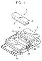
- Fig. 1 is a perspective view of an inkjet head of an embodiment of the present invention and a printer body, to which the inkjet head is mounted, of a form used in the present invention.
- Fig. 2 is an enlarged transverse sectional view of the inkjet head shown in Fig. 1.
- Fig. 3 is a side view of specific examples of a head cap, a cleaning roller, and an ink receiving section shown in Fig. 2.
- Fig. 4 is a plan view of the specific examples of the head cap, the cleaning roller, and the ink receiving section.
- Fig. 5 is a sectional view taken along line V-V of Fig. 4.
- Fig. 6 illustrates means for detecting a timing of a preliminary discharge operation from each ink discharge hole carried out when the head cap moves relative to the print head.
- Figs. 7A and 7B schematically illustrate another form of the cleaning roller.
- Fig. 8 is a graph showing changes in an ink liquid penetration distance with respect to an ink absorbing member with time.
- Fig. 9 schematically illustrates still another form of the cleaning roller.
- Fig. 10 schematically illustrates another form of the ink receiving section of the head cap.
- Fig. 11 schematically illustrates still another form of the ink receiving section of the head cap.
- Figs. 12A to 12F illustrate a cleaning operation using the cleaning roller and the head cap of the inkjet head.
- Fig. 13 is a perspective view of an inkjet printer of an embodiment of the present invention in which the inkjet head is mounted.
- Fig. 14 is a perspective view similarly showing the inkjet printer of the embodiment of the present invention in which the head cap is removed.
- Fig. 15 illustrates a specific mechanism in which the inkjet head shown in Fig. 1 is accommodated in a predetermined location of the printer body as a result of insertion thereof in the direction of arrow H, and an operation thereof.
- Fig. 16 illustrates the specific mechanism in which the inkjet head is secured to the predetermined location of the printer body by a head mounting-and-dismounting mechanism and in which the head cap is made movable, and an operation thereof.
- Fig. 17 illustrates the specific mechanism in which the head cap mounted to the bottom surface of an ink cartridge is being removed as a result of movement thereof in the direction of arrow A, and an operation thereof.
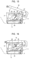
- Fig. 18 illustrates the specific mechanism in which the head cap successively moves in the direction of arrow A along a movement path P, and an operation thereof.
- Fig. 19 illustrates the specific mechanism in which the head cap is at a withdrawal position as a result of maximally moving in the direction of arrow A along the movement path P, and an operation thereof.
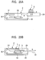
- Figs. 20A and 20B schematically illustrate another type of inkjet printer having the inkjet head mounted to the printer body through a tray.
- Fig. 1 is a perspective view of an inkjet head 1 of an embodiment of the present invention and a printer body 2, to which the inkjet head 1 is mounted, of a form used in the present invention.
- the inkjet head 1 is separately formed, and is of a type that is directly mounted to the printer body 2.
- the inkjet head 1 is accommodated in the direction of arrow H, and is set so as to be fixed to the printer body 2 in order to form an inkjet printer.
- the inkjet head 1 forms liquid ink into very fine particles by, for example, electrothermal conversion or electromechanical conversion, and discharges the very fine particles in order to blow ink dots onto a recording sheet.
- the inkjet head 1 comprises an ink cartridge 3, a print head 4, and a head cap 5.
- the ink cartridge 3 holds ink of one color or of a plurality of colors therein. Its housing is extended so as to be elongated in the widthwise direction of the printer body 2 shown in Fig. 1, that is, over the entire width of a recording sheet in the widthwise direction thereof. Although not shown, four divided ink chambers are formed inside the housing and are filled with ink of corresponding four colors, yellow Y, magenta M, cyan C, and black K.
- the ink cartridge 3 is formed of, for example, a hard resin.
- the print head 4 is provided at the bottom surface portion of the ink cartridge 3.
- the print head 4 forms the ink supplied from the ink cartridge 3 into very fine particles, and discharges the very fine particles.
- the print head 4 includes ink discharge surfaces 6 having very small ink-discharge holes provided in correspondence with the entire width of a recording sheet along the longitudinal direction of the ink cartridge 3.
- the ink discharge surfaces 6 extend in the longitudinal direction of the ink cartridge 3, and are provided in correspondence with the four colors of ink, yellow Y, magenta M, cyan C, and black K, respectively.
- the portions of the ink discharge surfaces 6 that include the ink-discharge holes of the corresponding colors of ink, Y, M, C, and K, and the portions thereof that include protrusions where head electrodes are covered with resin on both sides of the corresponding ink-discharge holes are formed so as to have undulating planar shapes.
- the head cap 5 is mounted to the bottom surface of the ink cartridge 3.
- the head cap 5 covers the ink discharge surfaces 6 of the print head 4 and protects them in order to prevent drying and clogging of the ink-discharge holes.
- the head cap 5 extends so as to be elongated to the same length as the housing of the ink cartridge 3, has the shape of a box that is shallow and that has an open top side, and moves relative to and is removably mounted to the print head 4.
- the head cap 5 moves, as indicated by arrows A and B, in a direction orthogonal to the longitudinal direction of the ink discharge surfaces 6 of the print head 4.
- the head cap 5 When the head cap 5 has moved in the direction of arrow A, it is removed from the ink cartridge 3, whereas, when the head cap 5 has moved back in the direction of arrow B, it is placed on the ink cartridge 3 again.
- the head cap 5 is formed of, for example, a hard resin.
- a cleaning roller 7 is provided at the inner side of the head cap 5.
- the cleaning roller 7 is a cleaning member for cleaning the ink discharge surfaces 6 of the print head 4, and is mounted at one side portion inside the head cap 5 in the longitudinal direction of the head cap 5. Therefore, the cleaning roller 7 is provided parallel to the longitudinal direction of the ink discharge surfaces 6 of the print head 4.
- the cleaning roller 7 moves in the direction of arrow A along with the head cap 5 in order to clean the ink discharge surfaces 6 of the print head 4.
- An ink receiving section 8 is similarly provided at the inner side of the head cap 5.
- the ink receiving section 8 receives preliminarily discharged ink from the ink-discharge holes of the print head 4, so that part of or the whole bottom surface of the shallow-box-shaped head cap 5 receives the preliminarily discharged ink.
- the head cap 5 is formed into an elongated shape in accordance with the width and length of the ink cartridge 3 shown in Fig. 1.
- the head cap 5 is formed with a bottom surface (lower portion) and into the shape of a shallow box in which a side of upstanding portions of side walls along the entire periphery is open.
- the head cap 5 moves, as indicated by the arrows A and B, in a direction orthogonal to the longitudinal direction of the ink discharge surfaces 6 of the print head 4.
- a positioning pawl 12 is provided at the top end portion of a side wall of the head cap 5 opposite to the cleaning roller 7. The positioning pawl 12 positions the head cap 5 as a result of being stopped by a side edge of the lower portion of the ink cartridge 3.
- the cleaning roller 7, which is formed into a circular cylindrical shape and which comes into contact with the ink discharge surfaces 6 of the print head 4 over the entire length of the ink discharge surfaces 6, is removably held near one of the side walls of the head cap 5 in the longitudinal direction thereof at the print head 4 side of the head cap 5. More specifically, as shown in Fig. 4, protruding pins 9 are provided at both end portions of the cleaning roller 7, and, as shown in Fig. 3, are held by substantially U-shaped upstanding holding members 10. Pin-receiving sections at the top portions of the holding members 10 can be resiliently widened and narrowed.
- the pin-receiving sections By pushing the pins 9 against the pin-receiving sections from thereabove, the pin-receiving sections are widened and receive the pins 9, and, thereafter, are narrowed and hold the pins 9. In contrast, by raising the pins 9 upward, the pin-receiving sections are widened, so as to allow removal of the pins 9.
- the circular cylindrical shape of the cleaning roller 7 is what is called a crown shape where the central portion in the longitudinal direction thereof is moderately thick.
- the cleaning roller 7 has this shape to prevent the cleaning roller 7 from moving out of contact with the ink discharge surfaces 6 when the central portion of the cleaning roller 7 in the longitudinal direction thereof flexes downward.
- the portion of the cleaning roller 7 that comes into contact with the ink discharge surfaces 6 is resilient and is formed of a material that absorbs ink. More specifically, the core material of the cleaning roller 7 is formed of, for example, a metal or a hard resin, while the peripheral portion thereof situated outwardly of the core material is formed of a resilient material and a porous material having an ink absorption property.
- a floating spring 11 is interposed at the portion where the cleaning roller 7 is held by the head cap 5.
- the floating spring 11 is means for biasing the cleaning roller 7 towards the ink discharge surfaces 6 of the print head 4; is, for example, a plate spring that is substantially U-shaped in side view; and is inserted below the pins 9 near the holding members 10.
- the cleaning roller 7 is such as to come into contact with the entire length of the ink discharge surfaces 6 of the print head 4 due to the biasing force of the floating spring 11 and the resilient force and the crown shape of the cleaning roller 7.
- the floating spring 11 is not limited to a substantially U-shaped plate spring, so that it may be a coil spring.
- the cleaning roller 7 is such as to be driven and rotated as a result of coming into contact with the ink discharge surfaces 6 of the print head 4. Therefore, as shown in Fig. 2, when the head cap 5 moves in the direction of arrow A, the cleaning roller 7 rotates while it comes into close contact with the entire length of the ink discharge surfaces 6 of the print head 4 with a proper pressure in order to, by this rotational movement, clean off the ink that has adhered to the ink discharge surfaces 6. In this case, it is possible to clean off the ink without injuring protective layers where head electrodes provided at the ink discharge surfaces 6 are covered with resin.
- the cleaning roller 7 may be secured so as not to rotate while it is in contact with any one of the ink discharge surfaces 6 of the print head 4.
- Fig. 3 by providing two pins 9 at both end portions of the cleaning roller 7 in the vertical direction, and by inserting the two pins 9 at both end portions into a substantially U-shaped groove of the holding members 10, the cleaning roller 7 is prevented from rotating. In this case, the cleaning roller 7 moves while it rubs against the ink discharge surfaces 6. Therefore, it is possible to clean off solidified ink stuck on the ink discharge surfaces 6, not to mention liquid ink stuck on the ink discharge surfaces 6.
- the cleaning roller 7 may be such as to rotate while it rubs against the ink discharge surfaces 6 of the print head 4 by limiting the rotation of the cleaning roller 7 by a braking mechanism.
- the braking mechanism is a mechanism in which a proper resilient member is interposed at the portion where the pins 9 provided at both end portions of the cleaning roller 7 are held by the holding members 10, and in which the pins 9 are press-fitted to a hole formed in the resilient member, or both end surfaces of the cleaning roller 7 are press-contacted to a side surface of the resilient member.
- the braking mechanism produces a proper braking force when the cleaning roller 7 rotates. In this case, since the cleaning roller 7 rotates slightly while it rubs against the ink discharge surfaces 6, it can clean off solidified ink stuck on the ink discharge surfaces 6, not to mention liquid ink stuck on the ink discharge surfaces 6, without injuring the ink discharge surfaces 6.
- an ink-absorbing member 13 is laid on a receiving surface, or bottom surface, of the ink receiving section 8 at the inner side of the head cap 5.
- the ink-absorbing member 13 is means for preventing ink preliminarily discharged from the print head 4 from spattering back; is formed of a porous, high molecular material, such as sponge, polyurethane, or polyurethane foam, and; as shown in Fig. 4, is laid over substantially the entire receiving surface of the ink-receiving section 8.
- the ink-absorbing member 13 is not laid below the large-diameter central portion of the crown-shaped cleaning roller 7 in order to provide clearance therebelow.
- the preliminarily discharged ink from the print head 4 shown in Fig. 2 is prevented from spattering back, and the ink can be absorbed thereby so that the ink does not collect at the ink-receiving section 8. Therefore, the problem that the preliminarily discharged ink re-adheres onto the ink discharge surfaces 6 as a result of being spattered back at the ink-receiving section 8 is prevented from occurring.
- the ink-absorbing member 13 that has absorbed the preliminarily discharged ink is removed from the ink-receiving section 8 and discarded in order to lay another ink-absorbing member 13, thereby making it possible to easily clean off the preliminarily discharged ink.
- the ink-receiving section 8 is described as being provided along the entire bottom surface of the head cap 5, the present invention is not limited thereto, so that the ink-receiving section 8 may be provided along part of the bottom surface of the head cap 5.
- the cleaning roller 7 may be slightly moved towards the center portion, and a partition plate may be provided between a cleaning-roller-7-side side wall of the head cap 5 and the cleaning roller 7 in order to form a chamber surrounded by the partition plate and the side wall as the ink-receiving section 8.
- the preliminary discharge of ink is carried out to, for example, suck and discharge ink inside the ink-discharge holes prior to printing or photographic printing for the purpose of preventing the problem that normal ink discharge becomes difficult to achieve due to increased viscosity or solidification of ink caused by evaporation drying of the ink inside the ink-discharge holes as described above.
- Fig. 6 means for detecting a timing of preliminarily discharging ink from the ink-discharge holes of the print head 4 when the head cap 5 moves relative to the print head 4 is provided at the head cap 5.
- the cap head 5 moves in a direction opposite to that in Fig. 2.
- the preliminary discharge timing detecting means comprises a position detection sheet 14 provided at the bottom surface side of the head cap 5 and a photoelectric switch 15 opposing the position detection sheet 14 and provided inside the printer body 2 shown in Fig. 1.
- the position detection sheet 14 is provided for examining locations corresponding to the colored ink discharge surfaces 6 of the print head 4 when the head cap 5 moves in the direction of arrow A, and has, for example, a light and dark pattern formed in correspondence with an arrangement pitch of the Y, M, C, and K ink discharge surfaces 6.
- the arrangement of the portions of the pattern is opposite to the order of arrangement of each of the colors, Y, M, C, and K for each of the ink discharge surfaces 6.
- the arrangement of the portions of the pattern on the position detection sheet 14 is displaced towards the back when viewed in the direction of arrow A.
- the photoelectric switch 15 is provided for detecting the light and dark pattern on the position detection sheet 14 that moves along with the head cap 5, and is formed by integrally combining a light-emitting section 16, such as a light-emitting diode (LED), and a light receiving detecting section 17, which is a photodiode.
- a light-emitting section 16 such as a light-emitting diode (LED)
- a light receiving detecting section 17 which is a photodiode.
- the light and dark pattern on the position detection sheet 14 changes its reflectivity with respect to the wavelength of light emitted from the light emitting section 16, and the light receiving detecting section 17 is sensitive to the wavelength of the reflected light.
- Figs. 7A and 7B schematically illustrate another form of the cleaning roller 7.
- the cleaning roller 7 is such as to rotate forward or backward by a rotation driving mechanism. More specifically, in Fig. 2, a rotary shaft of a motor (not shown) provided inside the printer body 2 is connected to the pins 9, provided at the cleaning roller 7, through a gear mechanism having a proper reduction ratio, so that the cleaning roller 7 is actively rotationally driven.
- the cleaning roller 7 is rotated by the motor in the same direction as the direction of movement of arrow A of the head cap 5 shown in Fig. 6 and with a rotating speed that is set so that an outer peripheral speed v 2 of the cleaning roller 7 is greater than a movement speed v 1 of the head cap 5.
- the ink discharge surfaces 6 are reliably cleaned by rubbing that is based on the difference in speeds between the ink discharge surfaces 6 of the print head 4 and the outer peripheral surface of the cleaning roller 7.
- the cleaning roller 7 may be made to rotate in a direction opposite to the direction of movement of arrow A of the head cap 5 shown in Fig. 6. In this case, rubbing occurs due to a difference between the directions of movement of the ink discharge surfaces 6 of the print head 4 and the outer peripheral surface of the cleaning roller 7, so that the ink discharge surfaces 6 are reliably cleaned.
- the ink discharge surfaces 6 of the print head 4 are cleaned by outer peripheral surface portions that are successively provided by the active rotation of the cleaning roller 7.
- the rate of increase of a penetration distance 1 is initially large, but gradually decreases with the passage of time t.
- Fig. 9 schematically illustrates still another form of the cleaning roller 7.
- the Y, M, C, and K colored ink discharge surfaces 6 are always cleaned by the same outer peripheral surface portions as a result of one rotation of the cleaning roller 7 because the outer peripheral surface portions of the cleaning roller 7 roll on the Y, M, C, and K colored ink discharge surfaces 6 as a result of the cleaning roller 7 being driven and rotating in the direction of arrow G while moving in the direction of arrow F. Therefore, a particular outer peripheral surface portion of the cleaning roller 7 always comes into contact with the same ink discharge surface 6, so that mixing of colors in that ink discharge surface 6 does not occur. Therefore, there is no possibility of the quality of printing and photographic printing by the inkjet head getting reduced.
- Fig. 10 schematically illustrates another form of the ink-receiving section 8 provided at the head cap 5.
- the receiving surface of the ink-receiving section 8 is formed into a rough surface.
- the rough surface is means for preventing preliminarily discharged ink from the print head 4 from being spattered back; is, for example, jagged, bumpy, or wavy; and causes the preliminarily discharged ink to be scattered sideways rather than being spattered back upward.
- the preliminarily discharged ink is prevented from re-adhering to the ink discharge surfaces 6 of the print head 4.
- Fig. 11 schematically illustrates still another form of the ink-receiving section 8 provided at the head cap 5.
- the receiving surface of the ink-receiving section 8 is formed into an inclined surface that inclines towards one side in the longitudinal direction of the ink discharge surfaces 6 of the print head 4.
- the inclined surface is means for preventing ink that has been preliminarily discharged from the print head 4 from being spattered back.
- the preliminarily discharged ink flows along the inclined surface and collects at an end at one side of the inclined surface, so that the receiving surface of the ink-receiving section 8 is maintained in a clean state.
- any ink remaining on the receiving surface after a previous preliminary discharge operation is spattered back by the currently preliminarily discharged ink in order to eliminate the possibility of the residual ink re-adhering to the ink discharge surfaces 6 of the print head 4.
- the receiving surface of the inclined ink-receiving section 8 may be formed into a rough surface.
- a description of the cleaning operation by the cleaning roller 7 and the head cap 5 of the inkjet head 1 having a structure such as those described above will be given with reference to Fig. 12.
- the head cap 5 moves in the direction of arrow A in order to clean the ink discharge surfaces 6 of the print head 4, after which a preliminary discharge operation of ink is carried out.
- Fig. 12A shows an initial state in which the head cap 5 is placed on the ink cartridge 3. From the state shown in Fig. 1, the inkjet head 1 is accommodated and set in the printer body 2.
- the head cap 5 is moved in the direction of arrow A relative to the ink cartridge 3 by a head cap removal signal.
- This causes the cleaning roller 7 to move in the direction of arrow A along with the head cap 5 with respect to the ink cartridge 3, so that, with the cleaning roller 7 being pushed against and brought into contact with the ink discharge surfaces 6 of the print head 4, the ink discharge surfaces 6 are cleaned.
- the cleaning roller 7 is driven and rotates while it is in contact with any one the ink discharge surfaces 6, the cleaning roller 7 is fixed, the rotation of the cleaning roller 7 is limited by a braking mechanism, or the cleaning roller 7 moves while being rotated in the forward or back direction by a motor.
- preliminary discharge ink 18 is ejected from the ink-discharge hole of the yellow Y ink discharge surface 6. Then, a preliminary discharge completion signal is sent to the ink-discharge hole of the yellow Y ink discharge surface 6 in order to stop the ejection of the preliminary discharge ink 18. Thereafter, similarly, in Fig. 6, each time the cleaning roller 7 successively finishes cleaning each of the M, C, and K ink discharge surfaces 6, the photoelectric switch 15 detects completion of the cleaning of each of the ink discharge surfaces 6 in order to send a preliminary discharge start signal and a preliminary discharge completion signal to each of the ink-discharge holes. By this, a timing of the preliminary discharge operation from each of the ink-discharge holes is controlled, so that the ink preliminary discharge operations are successively carried out.
- the head cap 5 moves maximally in the direction of arrow A, moves slightly upward, and settles in a withdrawal position. In this state, printing or photographic printing is performed on a recording sheet.
- a head cap placing signal is transmitted, so that, as shown in Fig. 12E, the head cap 5 moves in the direction of arrow B relative to the ink cartridge 3 from the aforementioned withdrawal position.
- This causes the cleaning roller 7 to move in the direction of arrow B along with the head cap 5 with respect to the ink cartridge 3, so that, with the cleaning roller 7 being pushed against and coming into contact with the ink discharge surfaces 6 of the print head 4, the cleaning roller 7 moves back while cleaning the ink discharge surfaces 6.
- the head cap 5 moves maximally in the direction of arrow B with respect to the ink cartridge 3, and covers the ink cartridge 3, thereby returning to its initial state. Then, the printer waits for the next printing or photographic printing command.
- the inkjet printer performs printing by forming ink from the inkjet head into very fine particles and discharging them, and blowing ink dots onto a recording sheet.
- Fig. 1 it comprises the inkjet head 1, the printer body 2, a head mounting-and-dismounting mechanism 19, and a head cap placing-and-removing mechanism 20.
- the inkjet printer is shown as a type in which the inkjet head 1 is directly mounted to the printer body 2.
- the inkjet head 1 forms liquid ink into very fine particles by, for example, electrothermal conversion or electromechanical conversion, and discharges the very fine particles in order to blow ink dots onto a recording sheet. Therefore, the inkjet head 1 has the same structure as that described in Figs. 1 to 12.
- the printer body 2 is provided to function as an inkjet printer by mounting the inkjet head 1 to a predetermined location thereof, and comprises a recording-sheet tray, a recording-sheet transporting system, an operational driving system, and a control circuit portion for controlling the entire printer body 2.
- reference numeral 21 denotes a discharged-sheet receiver to which sheets are discharged after printing.
- the head mounting-and-dismounting mechanism 19 is provided to mount the inkjet head 1 to and dismount it from a predetermined location of the printer body 2, and comprises, for example, an elongated bar member which holds down the top surface portion of the inkjet head 1 by insertion of the inkjet head 1 into the predetermined location, that is, a recess in the center portion of the printer body 2.
- the head mounting-and-dismounting mechanism 19 extends in the direction of the entire width of the printer body 2, and is such as to be, for example, raised and lowered in the vertical and the horizontal directions, respectively.
- the head cap placing-and-removing mechanism 20 causes the head cap 5 to move relative to the print head 4 (see Fig. 2) in order to uncover the ink discharge surfaces 6 (see Fig. 2), and causes the head cap 5 to be placed on the print head 4 after printing.
- the head cap placing-and-removing mechanism 20 is formed by, for example, engaging a pinion 23 and a rack 22, both of which are provided at a side surface of the printer body 2.
- a pin-like protrusion is provided at a side surface at the inner side of the rack 22, and is fitted to a recess formed in a corresponding portion of the outer-side surface of the head cap 5.
- the head cap placing-and-removing mechanism 20 is not limited to an engagement of the rack 22 and the pinion 23.
- a rubber roller pushes against both side surfaces of the head cap 5
- a motor is connected to a rotary shaft of the rubber roller, and the motor is rotated in order to move the head cap 5 in the direction of arrow A by friction of the rubber roller and to remove it.
- Fig. 15 shows a state in which the inkjet head 1 shown in Fig. 1 is accommodated in the predetermined location of the printer body 2 by insertion thereof in the direction of arrow H.
- the bottom ends of cap lock hooks 24 provided at both side end portions inside the inkjet head 1 engage corresponding stopper portions 26 at both side portions of the head cap 5 by a resilient force of a helical spring 25.
- the head cap 5 is integrally mounted to the ink cartridge 3.
- the head mounting-and-dismounting mechanism 19 is pushed down in the direction of arrow J and is secured.
- This causes a cap unlocking portion 27 provided at the bottom side portion of the head mounting-and-dismounting mechanism 19 to push down and rotate top end portions 28 of the cap lock hooks 24.
- this causes the bottom end portions of the cap lock hooks 24 to be lifted in order to disengage them from the corresponding stopper portions 26 at both side portions of the head cap 5.
- the inkjet head 1 is secured to the predetermined location of the printer body 2 by the head mounting-and-dismounting mechanism 19, and the head cap 5 becomes movable.
- the head cap placing-and-removing mechanism 20, shown in Fig 13, is operated in order to rotate the pinion 23 by a motor (not shown) and to move the rack 22 in the direction of arrow A.
- this causes the head cap 5, mounted to the bottom surface of the ink cartridge 3, to move, along with the rack 22, in the direction of arrow A and to be subjected to a removing operation.
- the cleaning roller 7 biased by the floating spring 11 starts cleaning the ink discharge surfaces 6 of the print head 4 provided at the bottom surface of the ink cartridge 3.
- reference character P denotes a path of movement of the head cap 5.
- the head cap 5 moves successively in the direction of arrow A along the movement path P.
- the cleaning roller 7 mounted to the head cap 5 each of the Y, M, C, and K colored ink discharge surfaces 6, shown in Fig. 2, are successively cleaned, and preliminary discharge operations of ink are carried out before or after the cleaning operation.
- the head cap 5 moves maximally in the direction of arrow A along the movement path P and is moved slightly upward, so that it settles in the withdrawal position, as shown in Fig. 14. In this state, printing or photographic printing is carried out on a recording sheet.
- the head cap 5 is moved slightly upward, the space required to accommodate it can be made small.
- the recording sheet passes below the printer head 4 provided at the bottom surface of the ink cartridge 3, the passage of the recording sheet may be guided by the bottom surface of the head cap 5.
- a rib for guiding the recording sheet may be provided at the bottom surface of the head cap 5.
- a water-repellency process may be carried out so that ink does not stick onto the recording sheet that has been subjected to printing.
- the head cap 5 moves in the direction of arrow B from the withdrawal position shown in Fig. 19 by the above-described operations performed in reverse order, and, as shown in Fig. 16, the head cap 5 returns to its initial state by returning to the bottom surface of the ink cartridge 3.
- an interlock mechanism may be provided to cause the head cap 5 at the withdrawal position to automatically return to its initial position shown in Fig. 15 when the power supply of the printer is turned off for some reason, or to prevent the head mounting-and-dismounting mechanism 19 from opening in a direction opposite to the direction of arrow J when the head cap 5 has not returned to its initial position shown in Fig. 15.
- the inkjet printer illustrated in Figs. 13 to 19 is of the type in which the inkjet head 1 is directly mounted to the printer body 2.
- the present invention is not limited thereto, so that an inkjet printer of the type in which the inkjet head 1 is mounted to the printer body 2 through a tray may similarly be used.
- a general description of another type of inkjet printer will be given with reference to Fig. 20.
- the inkjet head 1 that includes the head cap 5 integrally mounted to the ink cartridge 3 is mounted in the direction of arrow Q to a predetermined location at the inner side of a tray 29 which is provided so that it can advance and retreat with respect to the printer body 2. Thereafter, the tray 29 is moved in the direction of arrow R and is set inside the printer body 2. At this time, as shown in Fig. 20B, while the tray 29 is moving in the direction of arrow R, the head cap 5 is retained and stopped by proper retaining means provided inside the printer body 2. The tray 29 is provided for setting the inkjet head 1 inside the printer body 2 and for replacing it.
- reference numeral 30 denotes a recording sheet tray
- reference numeral 31 denotes a recording sheet
- reference numeral 32 denotes a feed roller
- reference numeral 33 denotes a feed belt
- reference numeral 34 denotes a sheet-discharge tray
- reference character S denotes the direction in which the recording sheet is discharged.
- the means for detecting a timing of a preliminary discharge operation from each ink discharge hole of the print head 4 shown in Fig. 6 is provided at the side of the ink cartridge 3 that moves in the direction of arrow R.
- the position detection sheet 14 may be provided at the top surface side of the ink cartridge 3, and the photoelectric switch 15 may be provided above the ink cartridge 3 and inside the printer body 2 so as to oppose the position detection sheet 14.
Landscapes
- Ink Jet (AREA)
Abstract
Description
Claims (14)
- A inkjet head comprising:an ink cartridge for holding ink of one color or of a plurality of colors therein;a print head including an ink discharge surface including an ink discharge hole for discharging ink supplied from the ink cartridge;a head cap, which moves relative to and is removably mounted to the print head, for protecting the ink discharge surface of the print head; anda cleaning member, provided at a print-head side of the head cap in a longitudinal direction of the print head, for cleaning the ink discharge surface of the print head.
- An inkjet head according to Claim 1, wherein the head cap is moved in a relative manner in a direction orthogonal to a longitudinal direction of the ink discharge surface of the print head in order to clean the ink discharge surface by the cleaning member which moves along with the head cap.
- An inkjet head according to Claim 1, wherein the print head preliminarily discharges ink from the ink discharge hole before or after cleaning the ink discharge surface by the cleaning member.
- An inkjet head according to Claim 3, further comprising an ink receiving section, provided at an inner side of the head cap, for receiving the ink preliminarily discharged from the ink discharge hole.
- An inkjet head according to Claim 3, further comprising means for detecting a timing of the preliminary discharge from the ink discharge hole of the print head when the head cap moves relative to the print head, the means being provided at either the ink cartridge or the head cap.
- An inkjet head according to Claim 1, wherein the cleaning member is formed with a circular cylindrical shape that comes into contact with the entire length of the ink discharge surface of the print head, and is removably held by the head cap.
- An inkjet head according to Claim 6, wherein a portion of the cleaning member that comes into contact with the ink discharge surface is resilient and is formed of an ink absorbing material.
- An inkjet head according to Claim 6, further comprising means for biasing the cleaning member towards the ink discharge surface of the print head, the means being provided at a portion where the cleaning member is held by the head cap.
- An inkjet head according to Claim 6, wherein the cleaning member is secured so as not to rotate when the cleaning member is in contact with the ink discharge surface of the print head, or rotation of the cleaning member is limited by a braking mechanism so that the cleaning member rotates while rubbing against the ink discharge surface.
- An inkjet head according to Claim 6, wherein the cleaning member is driven and rotates by coming into contact with the ink discharge surface of the print head, or wherein the cleaning member rotates in a forward direction or a backward direction by a rotational driving mechanism.
- An inkjet head according to Claim 6, wherein a cross-sectional peripheral length of the cleaning member is equal to a movement distance covered by the cleaning member when the cleaning member is driven and rotates by coming into contact with the ink discharge surface of the print head.
- An inkjet head according to Claim 4, further comprising means for preventing the preliminarily discharged ink from being spattered back, the means being provided at a receiving surface of the ink receiving section.
- An inkjet printer for carrying out a printing operation by forming ink from an inkjet head into very fine particles and discharging the very fine particles in order to blow ink dots on a recording sheet, the inkjet printer comprising:the inkjet head which comprises an ink cartridge for holding ink of one color or of a plurality of colors therein; a print head including an ink discharge surface including an ink discharge hole for discharging ink supplied from the ink cartridge; a head cap, which moves relative to and is removably mounted to the print head, for protecting the ink discharge surface of the print head; and a cleaning member, provided at a print-head side of the head cap in a longitudinal direction of the print head, for cleaning the ink discharge surface of the print head;a head mounting-and-dismounting mechanism for mounting and securing the inkjet head to a predetermined location of a printer body and for dismounting the inkjet head from the predetermined location of the printer body; anda head cap placing-and-removing mechanism for uncovering the ink discharge surface and for placing the head cap after completion of the printing operation by, with the inkjet head being secured to the predetermined location of the printer body, moving the head cap relative to the print head.
- An inkjet printer according to Claim 13, further comprising an ink receiving section, provided at an inner side of the head cap of the inkjet head, for receiving ink preliminarily discharged from the ink discharge hole.
Applications Claiming Priority (2)
| Application Number | Priority Date | Filing Date | Title |
|---|---|---|---|
| JP2001045271 | 2001-02-21 | ||
| JP2001045271A JP4945843B2 (en) | 2001-02-21 | 2001-02-21 | Inkjet head and inkjet printer |
Publications (2)
| Publication Number | Publication Date |
|---|---|
| EP1236576A1 true EP1236576A1 (en) | 2002-09-04 |
| EP1236576B1 EP1236576B1 (en) | 2005-02-02 |
Family
ID=18907100
Family Applications (1)
| Application Number | Title | Priority Date | Filing Date |
|---|---|---|---|
| EP02003565A Expired - Lifetime EP1236576B1 (en) | 2001-02-21 | 2002-02-15 | Inkjet head and ink jet printer |
Country Status (7)
| Country | Link |
|---|---|
| US (1) | US6637856B2 (en) |
| EP (1) | EP1236576B1 (en) |
| JP (1) | JP4945843B2 (en) |
| KR (1) | KR100870622B1 (en) |
| CN (2) | CN1190323C (en) |
| DE (1) | DE60202797T2 (en) |
| SG (1) | SG115451A1 (en) |
Cited By (3)
| Publication number | Priority date | Publication date | Assignee | Title |
|---|---|---|---|---|
| WO2003076192A1 (en) * | 2002-03-14 | 2003-09-18 | Sony Corporation | Liquid ejecting head, method of cleaning the ejecting head, and liquid ejecting device |
| WO2005002859A1 (en) | 2003-07-04 | 2005-01-13 | Sony Corporation | Liquid-discharging device and method of controlling the same |
| EP3608117A1 (en) * | 2018-08-10 | 2020-02-12 | Canon Kabushiki Kaisha | Inkjet printing apparatus |
Families Citing this family (46)
| Publication number | Priority date | Publication date | Assignee | Title |
|---|---|---|---|---|
| AUPQ439299A0 (en) | 1999-12-01 | 1999-12-23 | Silverbrook Research Pty Ltd | Interface system |
| US7407257B2 (en) * | 1999-05-25 | 2008-08-05 | Silverbrook Research Pty Ltd | Mobile device including a force transfer mechanism |
| AUPQ056099A0 (en) * | 1999-05-25 | 1999-06-17 | Silverbrook Research Pty Ltd | A method and apparatus (pprint01) |
| JP2003316266A (en) * | 2002-04-22 | 2003-11-07 | Sii P & S Inc | Thermal activation apparatus of heat-sensitive adhesive sheet and printer apparatus |
| JP4019829B2 (en) * | 2002-07-10 | 2007-12-12 | ソニー株式会社 | Image forming apparatus and control method thereof |
| JP4019835B2 (en) * | 2002-07-18 | 2007-12-12 | ソニー株式会社 | Image forming apparatus and control method thereof |
| US6814421B2 (en) * | 2002-10-24 | 2004-11-09 | Hewlett-Packard Development Company, L.P. | Printing device and method |
| US6869162B2 (en) | 2003-03-27 | 2005-03-22 | Hewlett-Packard Development Company, L.P. | Printing device and method for servicing same |
| JP4277591B2 (en) * | 2003-06-20 | 2009-06-10 | ソニー株式会社 | Liquid ejection device |
| JP2005007785A (en) | 2003-06-20 | 2005-01-13 | Sony Corp | Method and device for detecting quantity of waste liquid and liquid ejector |
| JP3922222B2 (en) * | 2003-07-04 | 2007-05-30 | ソニー株式会社 | Liquid ejection apparatus and control method thereof |
| US7380903B2 (en) | 2003-09-10 | 2008-06-03 | Fujifilm Corporation | Inkjet recording apparatus, and ink discharge surface cleaning method and device |
| JP3918117B2 (en) * | 2003-09-10 | 2007-05-23 | 富士フイルム株式会社 | Ink jet recording apparatus and ink discharge surface cleaning method |
| KR101045469B1 (en) * | 2003-12-29 | 2011-06-30 | 엘지디스플레이 주식회사 | Ink jet head cleaning apparatus |
| JP2005193568A (en) * | 2004-01-08 | 2005-07-21 | Sony Corp | Nozzle cap, head cap unit, and liquid ejection head |
| JP4501447B2 (en) * | 2004-02-16 | 2010-07-14 | ソニー株式会社 | Head cap, head cartridge, and liquid ejection device |
| JP4186834B2 (en) * | 2004-02-16 | 2008-11-26 | ソニー株式会社 | Liquid ejection apparatus and control method thereof |
| US7334865B2 (en) * | 2004-03-03 | 2008-02-26 | Sony Corporation | Head cartridge and liquid ejection apparatus |
| JP4543719B2 (en) * | 2004-03-24 | 2010-09-15 | ソニー株式会社 | Liquid ejection device and method for driving liquid ejection device |
| JP2006248102A (en) * | 2005-03-11 | 2006-09-21 | Shibaura Mechatronics Corp | Ink jet coating device and cleaning method of ink jet head |
| KR100611994B1 (en) * | 2005-04-04 | 2006-08-11 | 삼성전자주식회사 | Inkjet head and inkjet printer with the same |
| US7470019B2 (en) * | 2005-05-09 | 2008-12-30 | Silverbrook Research Pty Ltd | Mobile telecommunications device with a capper moveable between capping and uncapping positions by the printhead |
| US7284921B2 (en) | 2005-05-09 | 2007-10-23 | Silverbrook Research Pty Ltd | Mobile device with first and second optical pathways |
| US20060250477A1 (en) * | 2005-05-09 | 2006-11-09 | Silverbrook Research Pty Ltd | Cartridge with capping mechanism for use in a mobile device |
| JP4742683B2 (en) | 2005-06-02 | 2011-08-10 | ソニー株式会社 | Liquid detection device and liquid ejection device |
| KR100765754B1 (en) | 2005-07-04 | 2007-10-15 | 삼성전자주식회사 | Print head wiper, inkjet image forming apparatus with the same, and maintenance method of the inkjet image forming apparatus |
| KR100782816B1 (en) | 2005-08-19 | 2007-12-06 | 삼성전자주식회사 | Inkjet image forming apparatus and mainmtenance method thereof |
| KR100727971B1 (en) | 2005-09-01 | 2007-06-14 | 삼성전자주식회사 | Wiper, Cleaning apparatus, and Inkjet image forming apparatus with the same |
| JP4887737B2 (en) * | 2005-10-31 | 2012-02-29 | ブラザー工業株式会社 | Inkjet recovery device |
| US7992961B2 (en) * | 2006-03-31 | 2011-08-09 | Brother Kogyo Kabushiki Kaisha | Ink-jet head |
| US7798599B2 (en) * | 2007-02-27 | 2010-09-21 | Hewlett-Packard Development Company, L.P. | Fluid-ejection device service station |
| DE102007057819A1 (en) * | 2007-11-30 | 2009-06-04 | Francotyp-Postalia Gmbh | Device for keeping an ink print head clean |
| TWI388947B (en) * | 2008-04-03 | 2013-03-11 | Kinpo Elect Inc | A microparticle/aerosol-collecting device for office machine |
| TW200946357A (en) * | 2008-05-13 | 2009-11-16 | Kinpo Elect Inc | A device for cleaning out residual ink |
| TWI354625B (en) * | 2009-06-12 | 2011-12-21 | Kinpo Elect Inc | Aerosol clearing apparatus of inkjet printer |
| JP2009279938A (en) * | 2009-07-09 | 2009-12-03 | Silverbrook Research Pty Ltd | Inkjet printer cartridge having integrated maintenance station |
| KR20110020535A (en) * | 2009-08-24 | 2011-03-03 | 삼성전자주식회사 | Wiping assembly and image forming apparatus having the same |
| KR20110091274A (en) * | 2010-02-05 | 2011-08-11 | 삼성전기주식회사 | Inkjet head cleaning apparatus |
| WO2011155324A1 (en) * | 2010-06-08 | 2011-12-15 | シャープ株式会社 | Inkjet application device |
| KR101250928B1 (en) * | 2010-11-29 | 2013-04-04 | 주식회사 나래나노텍 | Improved Priming Roller, and Priming Processing Apparatus Having the Same |
| SG192296A1 (en) | 2012-01-09 | 2013-08-30 | Venture Corp Ltd | An apparatus and methods for dispensing at least one segment of a printed media sheet with a plurality of segments |
| US8894180B2 (en) | 2013-01-17 | 2014-11-25 | Hewlett-Packard Development Company, L.P. | Guide for a wiping assembly |
| JP2017008459A (en) * | 2015-06-25 | 2017-01-12 | 株式会社キョーエース | Napped blanket manufacturing process and apparatus |
| JP6746954B2 (en) * | 2016-03-01 | 2020-08-26 | 株式会社リコー | Device for ejecting liquid |
| CN108973333B (en) * | 2018-08-07 | 2019-06-18 | 江苏双兴工贸有限公司 | A kind of paint glass manufacturing and processing equipment |
| CN110406261B (en) * | 2019-07-31 | 2020-07-17 | 湖南长城信息金融设备有限责任公司 | Automatic sealing rotary cleaning device for ink box spray head |
Citations (3)
| Publication number | Priority date | Publication date | Assignee | Title |
|---|---|---|---|---|
| EP0410691A1 (en) * | 1989-07-25 | 1991-01-30 | Seiko Instruments Inc. | An ink jet head capping device |
| EP0896881A2 (en) * | 1997-08-11 | 1999-02-17 | Nec Corporation | Ink jet recording device |
| US5896144A (en) * | 1995-08-29 | 1999-04-20 | Oki Data Corporation | Ink jet recording apparatus having unitary cap with wiper portion formed therewith |
Family Cites Families (20)
| Publication number | Priority date | Publication date | Assignee | Title |
|---|---|---|---|---|
| JPS62196153A (en) * | 1986-02-21 | 1987-08-29 | Nec Corp | Ink jet head cleaning mechanism |
| US5040000A (en) | 1988-05-12 | 1991-08-13 | Canon Kabushiki Kaisha | Ink jet recording apparatus having a space saving ink recovery system |
| JP2761072B2 (en) * | 1990-02-02 | 1998-06-04 | キヤノン株式会社 | Ink jet recording apparatus and recording mechanism |
| JPH04115953A (en) * | 1990-09-06 | 1992-04-16 | Seikosha Co Ltd | Ink jet printer |
| JPH04185450A (en) * | 1990-11-20 | 1992-07-02 | Seiko Epson Corp | Cleaning device for ink jet printer |
| JPH05238015A (en) * | 1992-02-26 | 1993-09-17 | Canon Inc | Ink jet recording apparatus |
| JP3110151B2 (en) * | 1992-04-14 | 2000-11-20 | キヤノン株式会社 | Ink jet recording device |
| JPH05330185A (en) * | 1992-06-02 | 1993-12-14 | Canon Inc | Recording apparatus and recording head |
| JP3535885B2 (en) | 1992-12-16 | 2004-06-07 | セイコーエプソン株式会社 | Ink jet recording device |
| JPH07137287A (en) * | 1993-06-29 | 1995-05-30 | Canon Inc | Ink jet recorder |
| US5617124A (en) | 1994-03-25 | 1997-04-01 | Hewlett-Packard Company | Self-cleaning service station for inkjet printing mechanisms |
| JPH09220810A (en) * | 1996-02-19 | 1997-08-26 | Matsushita Graphic Commun Syst Inc | Cleaning device of ink jet recording head |
| JPH1016316A (en) | 1996-06-27 | 1998-01-20 | Brother Ind Ltd | Printing apparatus |
| JPH1044447A (en) * | 1996-08-08 | 1998-02-17 | Minolta Co Ltd | Maintenance apparatus of ink jet head |
| DE69820909T2 (en) | 1997-03-25 | 2004-07-29 | Seiko Epson Corp. | Ink jet recording device and ink suction method for a recording head |
| JPH10278299A (en) * | 1997-04-04 | 1998-10-20 | Canon Inc | Ink jet recorder and method for ink jet recording |
| JP3924979B2 (en) * | 1998-03-24 | 2007-06-06 | コニカミノルタホールディングス株式会社 | Liquid ejection device |
| JP2000185409A (en) * | 1998-12-22 | 2000-07-04 | Toshiba Corp | Ink jet recording apparatus |
| KR100307780B1 (en) * | 1998-12-31 | 2001-12-28 | 이형도 | Cleaning device for inkjet print head |
| KR100341812B1 (en) * | 2000-02-21 | 2002-06-24 | 윤종용 | Wiper cleaning device in inkjet printer |
-
2001
- 2001-02-21 JP JP2001045271A patent/JP4945843B2/en not_active Expired - Fee Related
-
2002
- 2002-02-14 US US10/075,695 patent/US6637856B2/en not_active Expired - Lifetime
- 2002-02-15 SG SG200200811A patent/SG115451A1/en unknown
- 2002-02-15 EP EP02003565A patent/EP1236576B1/en not_active Expired - Lifetime
- 2002-02-15 DE DE60202797T patent/DE60202797T2/en not_active Expired - Lifetime
- 2002-02-20 KR KR1020020008936A patent/KR100870622B1/en not_active IP Right Cessation
- 2002-02-21 CN CNB021052239A patent/CN1190323C/en not_active Expired - Fee Related
- 2002-02-21 CN CNB2004100617968A patent/CN1256239C/en not_active Expired - Fee Related
Patent Citations (3)
| Publication number | Priority date | Publication date | Assignee | Title |
|---|---|---|---|---|
| EP0410691A1 (en) * | 1989-07-25 | 1991-01-30 | Seiko Instruments Inc. | An ink jet head capping device |
| US5896144A (en) * | 1995-08-29 | 1999-04-20 | Oki Data Corporation | Ink jet recording apparatus having unitary cap with wiper portion formed therewith |
| EP0896881A2 (en) * | 1997-08-11 | 1999-02-17 | Nec Corporation | Ink jet recording device |
Cited By (9)
| Publication number | Priority date | Publication date | Assignee | Title |
|---|---|---|---|---|
| WO2003076192A1 (en) * | 2002-03-14 | 2003-09-18 | Sony Corporation | Liquid ejecting head, method of cleaning the ejecting head, and liquid ejecting device |
| US7156485B2 (en) | 2002-03-14 | 2007-01-02 | Sony Corporation | Liquid discharge head, cleaning method thereof, and liquid discharge apparatus |
| WO2005002859A1 (en) | 2003-07-04 | 2005-01-13 | Sony Corporation | Liquid-discharging device and method of controlling the same |
| EP1642721A1 (en) * | 2003-07-04 | 2006-04-05 | Sony Corporation | Liquid-discharging device and method of controlling the same |
| EP1642721A4 (en) * | 2003-07-04 | 2008-10-01 | Sony Corp | Liquid-discharging device and method of controlling the same |
| EP3608117A1 (en) * | 2018-08-10 | 2020-02-12 | Canon Kabushiki Kaisha | Inkjet printing apparatus |
| CN110816049A (en) * | 2018-08-10 | 2020-02-21 | 佳能株式会社 | Ink jet printing apparatus |
| US10994542B2 (en) | 2018-08-10 | 2021-05-04 | Canon Kabushiki Kaisha | Inkjet printing apparatus |
| CN110816049B (en) * | 2018-08-10 | 2021-12-10 | 佳能株式会社 | Ink jet printing apparatus |
Also Published As
| Publication number | Publication date |
|---|---|
| KR100870622B1 (en) | 2008-11-27 |
| DE60202797D1 (en) | 2005-03-10 |
| EP1236576B1 (en) | 2005-02-02 |
| CN1256239C (en) | 2006-05-17 |
| KR20020068465A (en) | 2002-08-27 |
| US20020126176A1 (en) | 2002-09-12 |
| DE60202797T2 (en) | 2006-01-19 |
| SG115451A1 (en) | 2005-10-28 |
| US6637856B2 (en) | 2003-10-28 |
| CN1190323C (en) | 2005-02-23 |
| CN1371807A (en) | 2002-10-02 |
| CN1565849A (en) | 2005-01-19 |
| JP4945843B2 (en) | 2012-06-06 |
| JP2002240309A (en) | 2002-08-28 |
Similar Documents
| Publication | Publication Date | Title |
|---|---|---|
| EP1236576B1 (en) | Inkjet head and ink jet printer | |
| US6938980B2 (en) | Image forming apparatus and its control method | |
| KR100975453B1 (en) | Cleaning member, head cleaning method and image forming device | |
| US7997679B2 (en) | Image forming apparatus and controlling method therefor | |
| US20070091141A1 (en) | Ink-jet image forming apparatus to maintain a nozzle unit | |
| EP1642721B1 (en) | Liquid-discharging device | |
| JP4019835B2 (en) | Image forming apparatus and control method thereof | |
| JP2009292030A (en) | Maintenance recovery apparatus and droplet ejector | |
| JP3931698B2 (en) | Cleaning member, head cleaning method, and image forming apparatus | |
| JP4360225B2 (en) | Liquid discharge head cleaning device and liquid discharge device | |
| JP2003266716A (en) | Inkjet head, method for cleaning head, and imaging apparatus | |
| JP4501447B2 (en) | Head cap, head cartridge, and liquid ejection device | |
| JP2002264349A (en) | Head cleaning device, ink jet head and ink jet printer | |
| JP4175043B2 (en) | Image forming apparatus and control method thereof | |
| JP4175046B2 (en) | Image forming apparatus and control method thereof | |
| JP3931699B2 (en) | Cleaning member, head cleaning method, and image forming apparatus | |
| JP2003266746A (en) | Ink jet head, method for cleaning head and imaging apparatus | |
| JP2003266712A (en) | Inkjet head, method for cleaning head, and imaging apparatus | |
| JP2005022317A (en) | Liquid ejector and control method therefor | |
| JP3885775B2 (en) | Liquid ejection apparatus and control method thereof | |
| JP2005022314A (en) | Liquid ejector and control method therefor |
Legal Events
| Date | Code | Title | Description |
|---|---|---|---|
| PUAI | Public reference made under article 153(3) epc to a published international application that has entered the european phase |
Free format text: ORIGINAL CODE: 0009012 |
|
| AK | Designated contracting states |
Kind code of ref document: A1 Designated state(s): AT BE CH CY DE DK ES FI FR GB GR IE IT LI LU MC NL PT SE TR |
|
| AX | Request for extension of the european patent |
Free format text: AL;LT;LV;MK;RO;SI |
|
| 17P | Request for examination filed |
Effective date: 20030204 |
|
| AKX | Designation fees paid |
Designated state(s): DE FR GB IT |
|
| GRAP | Despatch of communication of intention to grant a patent |
Free format text: ORIGINAL CODE: EPIDOSNIGR1 |
|
| 17Q | First examination report despatched |
Effective date: 20040726 |
|
| GRAS | Grant fee paid |
Free format text: ORIGINAL CODE: EPIDOSNIGR3 |
|
| GRAA | (expected) grant |
Free format text: ORIGINAL CODE: 0009210 |
|
| AK | Designated contracting states |
Kind code of ref document: B1 Designated state(s): DE FR GB IT |
|
| REG | Reference to a national code |
Ref country code: GB Ref legal event code: FG4D |
|
| REG | Reference to a national code |
Ref country code: IE Ref legal event code: FG4D |
|
| REF | Corresponds to: |
Ref document number: 60202797 Country of ref document: DE Date of ref document: 20050310 Kind code of ref document: P |
|
| PLBE | No opposition filed within time limit |
Free format text: ORIGINAL CODE: 0009261 |
|
| STAA | Information on the status of an ep patent application or granted ep patent |
Free format text: STATUS: NO OPPOSITION FILED WITHIN TIME LIMIT |
|
| 26N | No opposition filed |
Effective date: 20051103 |
|
| ET | Fr: translation filed | ||
| PGFP | Annual fee paid to national office [announced via postgrant information from national office to epo] |
Ref country code: FR Payment date: 20120227 Year of fee payment: 11 |
|
| PGFP | Annual fee paid to national office [announced via postgrant information from national office to epo] |
Ref country code: DE Payment date: 20120221 Year of fee payment: 11 |
|
| PGFP | Annual fee paid to national office [announced via postgrant information from national office to epo] |
Ref country code: IT Payment date: 20120223 Year of fee payment: 11 Ref country code: GB Payment date: 20120221 Year of fee payment: 11 |
|
| REG | Reference to a national code |
Ref country code: GB Ref legal event code: 746 Effective date: 20120703 |
|
| REG | Reference to a national code |
Ref country code: DE Ref legal event code: R084 Ref document number: 60202797 Country of ref document: DE Effective date: 20120614 |
|
| GBPC | Gb: european patent ceased through non-payment of renewal fee |
Effective date: 20130215 |
|
| REG | Reference to a national code |
Ref country code: FR Ref legal event code: ST Effective date: 20131031 |
|
| REG | Reference to a national code |
Ref country code: DE Ref legal event code: R119 Ref document number: 60202797 Country of ref document: DE Effective date: 20130903 |
|
| PG25 | Lapsed in a contracting state [announced via postgrant information from national office to epo] |
Ref country code: IT Free format text: LAPSE BECAUSE OF NON-PAYMENT OF DUE FEES Effective date: 20130215 |
|
| PG25 | Lapsed in a contracting state [announced via postgrant information from national office to epo] |
Ref country code: GB Free format text: LAPSE BECAUSE OF NON-PAYMENT OF DUE FEES Effective date: 20130215 Ref country code: DE Free format text: LAPSE BECAUSE OF NON-PAYMENT OF DUE FEES Effective date: 20130903 Ref country code: FR Free format text: LAPSE BECAUSE OF NON-PAYMENT OF DUE FEES Effective date: 20130228 |