This application claims priority to Japanese patent application serial numbers
2001-57158 and 2001-238392.
The present invention relates to a blade clamping devices that can be utilized, e.g.,
with jigsaws and other reciprocating tools.
A known blade clamping device for a jigsaw is taught in US Patent No. 5,306,025.
This blade clamping device affixes a saw blade to a reciprocating drive shaft or plunger.
The blade clamping device includes a centering sleeve that extends from the drive shaft and
the centering sleeve includes an external threaded section. A clamping sleeve is rotatably
mounted on the external threaded section of the centering sleeve. By rotating the
clamping sleeve about the longitudinal axis of the drive shaft and the centering sleeve, the
blade clamping device can be moved from a blade locking position (bladc clamping
position) to a blade replacement position. In the blade replacement position, the saw blade
can be removed from the blade clamping device and a new saw blade can be inserted into
the blade clamping device. The blade clamping device is then locked in the blade locking
position by rotating the clamping sleeve back to the blade locking position. A torsion
spring normally biases the clamping sleeve towards the blade locking position.
A connecting bush (collar) is rotatably mounted around the clamping sleeve. The
connecting bush includes a gripping member (tab) that extends through an aperture defined
in the jigsaw housing. The connecting bush is operably coupled to the clamping sleeve,
such that rotating or pivoting the gripping member with respect to the jigsaw housing will
cause the clamping sleeve to rotate. However, during a sawing operation, the connecting
bush does not contact the clamping sleeve. Therefore, the blade clamping device can
freely reciprocate together with the drive shaft without interference from the connecting
bush. Further, the gripping member allows the operator to rotate or pivot the clamping
sleeve to the blade replacement position without directly touching the clamping sleeve.
However, the clamping sleeve of US Patent No. 5,306,025 can rotate past the
blade replacement position (i.e., the rotational range of the clamping sleeve is not
restricted). Therefore, in order to remove the saw blade from the blade clamping device,
the clamping sleeve must be accurately and precisely rotated to the blade replacement
position, so that the saw blade receiving slots within the blade clamping device will
properly align. If the clamping sleeve is not accurately and precisely positioned in the
blade replacement position, the saw blade can not be easily removed from the blade
clamping device, because the blade slots are not aligned, and thus, a saw blade can not be
inserted into or removed from the blade clamping device.
In order to accurately define the blade replacement position, the aperture in the
jigsaw housing is designed so that the gripping member of the connecting bush abuts an
edge of the aperture when the clamping device reaches the blade replacement position.
Thus, the aperture of the jigsaw housing is designed to limit the pivotal range of the
clamping sleeve, so that the clamping sleeve will stop at the blade replacement position.
Consequently, the relative positional relationships of the clamping sleeve, the
connection bush, the gripping member and the jigsaw housing aperture are critical for
accurately determining the blade replacement position. If all of these structures are not
accurately manufactured and/or accurately positioned during assembly, it may be difficult
or impossible to accurately position the blade clamping device in the blade replacement
position. Therefore, this known design suffers a significant drawback in being difficult to
accurately and reliably design and manufacture.
It is, accordingly, one object of the present teachings to teach blade clamps or
blade clamping devices that facilitate accurate and reliable positioning of the blade
replacement position using relatively simple structures. Such blade clamps may be
advantageously utilized with blades having positioning projections (or dogs) extending
from respective sides of the blade, although the present teachings are not limited to such
blades.
Thus, in one embodiment of the present teachings, jigsaw are taught as
representative examples of reciprocating power tools that arc particularly suited for the
present blade clamps. Naturally, the present teachings are not limited to jigsaws and the
present blade clamps can be advantageously utilized in a variety of applications and with a
variety of tools.
Generally speaking, jigsaws may include a housing, a reciprocating drive shaft
driven by a motor, a blade clamp and a saw blade. The drive shaft is also known in the art
as a plunger or a spindle and such terms arc interchangeable. In one embodiment of the
present teachings, the blade clamp may include a tab that can be manually rotated or
pivoted by the operator of the jigsaw. Further, the blade clamp may preferably include a
stopper that accurately stops the blade clamp in the blade replacement position.
Therefore, it is not necessary to utilize an aperture in the jigsaw housing as a means for
accurately stopping the blade clamp in the blade replacement position. Instead, the
stopper is preferably disposed internally within the blade clamp and thus, can more reliably
and accurately position the blade clamp in the blade replacement position than known blade
clamps. Consequently, the blade replacement position is not determined by the relative
positional relationships of the tab or gripper member and the aperture of the power tool
housing, thereby enabling the construction of more reliable blade clamping devices.
Optionally, the jigsaw may include an electric motor that serves as a drive source
for the drive shaft. Further, a transmission optionally may be included to convert
rotational movement of the drive source into substantially linear reciprocating movement of
the drive shaft. A variety of drives sources and transmissions may be utilized with the
present teachings and the present blade clamps are not limited to any particular drive source
and/or transmission.
The present blade clamps may be affixed to a distal end of the drive shaft.
Further, the present blade clamps may generally include a rod, a pushpin, and a rotatable
sleeve. Further, a pivotable or rotatable collar may be disposed around the rotatable
sleeve and preferably may be pivotally coupled to the housing. The collar may selectively
engage the rotatable sleeve so as to rotatc the blade clamp to the blade replacement
position. The collar may preferably include a tab or other gripping member that permits
the operator to manually manipulate the collar in order to rotate or pivot to the collar, and
thereby pivot or rotate the blade clamp to the blade replacement position.
In one embodiment of the present teachings, the rod may be affixed to a lower or
distal end of the drive shaft. A blade receiving portion (recess) may be defined within the
rod. A base end of the blade may be inserted into the blade receiving portion so that the
longitudinal axis of the blade is continuous, or substantially continuous, with the
longitudinal axis (i.e., the reciprocating axis) of the drive shaft. The blade receiving
portion may be arranged and constructed to as to be capable of receiving blades having a
variety of different thickness. Further, a slot preferably extends from the blade receiving
portion along the longitudinal axis of the rod. The slot is preferably designed to guide the
blade into the blade receiving portion and to support the blade during operation.
In another embodiment of the present teachings, the rod may include an aperture
that extends in a lateral direction of the rod (i.e., a direction perpendicular to the
longitudinal or reciprocating axis of the rod). Further, the aperture preferably
communicates with the rod slot and the aperture is preferably defined substantially
perpendicular to the rod slot. A pushpin may be slidably disposed within the ap erture.
For example, the distal end of the pushpin may be selectively moved so as to contact or
abut a side face of the blade when the blade has been inserted into the rod slot and blade
receiving portion of the rod. Therefore, the pushpin can fix the position of the blade
within the blade slot, so that the blade does not move or wobble during a sawing operation.
In another embodiment, the sleeve is preferably rotatably mounted around the rod
such that the sleeve can rotate or pivot about the longitudinal axis of the rod (or drive
shaft). The distal end of the sleeve preferably includes an opening (e.g., a slot) designed
to receive the blade. For example, the sleeve opening is preferably designed so that the
blade projections may pass through the sleeve opening and into the blade receiving portion
of the rod. Further, the sleeve preferably rotates or pivots about the longitudinal axis
between a blade locking position (e.g., a blade clamping position) and the blade
replacement position. As noted above, the collar and sleeve are preferably arranged and
constructed such that rotation or pivoting of the collar will cause the sleeve to rotate or
pivot. That is, the collar selectively engages the sleeve in order to rotate or pivot the
sleeve to the blade replacement position.
In another embodiment, a cam surface is preferably defined on an inner surface of
the sleeve. Further, the cam surface is preferably designed to slidably contact or abut a
head portion of the pushpin. In addition, the cam surface is preferably designed such that
rotation of the sleeve in a first direction causes the pushpin to extend further into the rod
aperture and the blade slot. Thus, rotation of the cam surface in the first direction urges
the pushpin towards the blade, so as to lock or clamp the blade within the blade slot of the
rod.
On the other hand, rotation of the sleeve in a second (opposite) direction
preferably permits the pushpin to withdraw from the blade slot defined in the rod so as to
permit a blade to be withdrawn from or inserted into the blade slot. As a result, when the
sleeve (and thus the cam surface) rotate in the second direction about the longitudinal axis
of the rod, the pushpin may be withdrawn from the blade slot and release contact with the
side face of the blade that is inserted in the blade slot.
In another embodiment of the present teachings, a first stopper is preferably
disposed on the sleeve in order to accurately define the blade replacement position of the
blade clamp. For example, the first stopper preferably restricts the sleeve from further
rotating or pivoting in relation to the rod when the blade replacement position has been
reached. In one representative embodiment, the first stopper may be defined on the cam
surface of the sleeve. In another representative embodiment, the first stopper may be
defined on an outer surface of the rod.
In another embodiment, the collar preferably includes a tab or other gripping
member that enables the operator to manually rotate or pivot the collar with respect to the
housing. Therefore, the operator can manually rotate or pivot the tab when the operator
wishes to remove and/or change the blade. Preferably, when the sleeve is disposed in the
initial position and/or the blade locking or clamping position, the blade receiving portion
and blade slot of the rod do not align with the sleeve opening (slot). Therefore, the blade
projections can not pass through the sleeve opening and the blade can not be removed from
the blade clamp. Moreover, if a blade is not inserted into the blade clamp when the blade
clamp is disposed in the initial position, a blade can not be inserted into the blade slot and
the blade receiving portion, because the sleeve opening is not aligned with the blade slot
and the blade receiving portion.
On the other hand, when the sleeve is disposed in the blade replacement position,
the blade slot and the blade receiving portion of the rod preferably align with the sleeve
opening (slot). Therefore, the blade projections can easily pass through the sleeve
opening of the sleeve and the blade can be inserted into or removed from the blade slot of
the blade clamp.
If a first stopper is utilized to restrict the sleeve from pivoting or rotating past the
blade replacement position, the sleeve can be accurately positioned in the blade
replacement position by simply adjusting the positional relationship between the sleeve and
the rod. In this case, the collar tab or gripper member is only required to pivot or rotate
the sleeve. The positional relationship of the collar tab with respect to the sleeve (or an
aperture in the tool housing) is not significant. Therefore, the sleeve can be accurately and
reliably positioned in the blade replacement position without requiring the positional
relationship of the housing, the collar, the rod, the sleeve, etc. to be accurately defined.
When the blade clamp is returned to the blade locking position after blade
replacement, the distal portion of the sleeve prevents the blade projections from passing
through the sleeve opening. Thereforc, the blade is reliably retained within the blade
clamp. As noted above, when the sleeve is rotated or pivoted toward the initial position,
the cam surface of the sleeve pushes or urges the pushpin toward the side face of the blade.
Consequently, the blade is reliably and firmly retained between the pushpin and a wall
surface of the blade slot, which wall surface is defined within the rod. The sleeve fixes
the blade in the clamped or locked state when the sleeve pivots or rotates from the blade
replacement position towards the initial position.
As noted above, the sleeve is preferably biased or urged toward the initial position.
For example, a torsion spring may be disposed around the rod and may be coupled to the
sleeve so as to bias the sleeve toward the initial position. The torsion spring may therefore
impart a force to the pushpin, which force will reliably retain the blade between the pushpin
and the side wall of the blade slot. By using a torsion spring disposed around the rod, the
length of the blade clamp along the axial direction of the drive shaft can be minimized.
The sleeve optionally also may include a second stopper. The second stopper
also may restrict the pivotal range of the sleeve with respect to the rod. For example, the
second stopper may be disposed in a position, so that the sleeve will be prevented from
pivoting past the initial position. That is, the second stopper may define the initial
position. If the second stopper restricts the pivotal range of the pushpin (and thus the
sleeve), the collar and the sleeve can be designed such that the collar will not contact the
sleeve in the initial position as well as the blade locking position. Therefore, if the jigsaw
is accidentally started without attaching a blade to the blade clamp, the collar and the sleeve
will not be damaged.
Thus, the first stopper may be defined at one end of the cam surface (or the outer
surface of the rod), so that the first stopper will contact or abut the pushpin when the sleeve
reaches the blade replacement position. Further, the second stopper may be defined at the
other end of the cam surface (or the outer surface of the rod), so that the second stopper will
contact or abut the pushpin when the sleeve reaches the initial position.
In another embodiment of the present teachings, the cam surface of the sleeve is
preferably designed so as to not actively push or urge the pushpin when the sleeve rotates
or pivots from the blade replacement position to a push start position. The push start
position may be defined at a predetermined angle displaced from the blade replacement
position. Thereafter, the cam surface will push or urge the pushpin when the sleeve is
rotated or pivoted past the push start position towards the initial position.
The rotation angle of the cam surface may include a range of play. In this range,
the cam does not push or urge the pushpin toward the side surface of the blade when the
sleeve rotates or pivots between the blade replacement position and the push start position.
Thus, as the sleeve rotates or pivots from the blade replacement position to the push start
position, the pushpin is preferably not urged or biased to contact the side surface of the
blade, which has been inserted into the blade slot and the blade receiving portion.
Therefore, rotation of the sleeve is not restricted between the blade replacement position
and the push start position. As a result, the sleeve can be reliably rotated or pivoted as far
as the push start position regardless of the thickness of the blade and the sleeve will support
the blade projections to prevent the blade from falling out of the blade clamp.
If the blade is thick and the cam surface does not include a range of play within
rotational angle, the pushpin may contact the blade before the sleeve has sufficiently rotated
toward the blade locking position. Consequently, further rotation of the sleeve may be
restricted or prevented and the blade may not be securely retained within the blade clamp.
The provision of a range of play ensures that the sleeve can sufficiently rotate so as to
prevent the blade from dropping out of the sleeve opening.
When the sleeve is further rotated or pivoted beyond the push start position toward
the initial position (i.e., toward the blade locking position), a friction angle may defined
between (1) a common normal at a contact point of the cam surface and the pushpin and (2)
a line passing through the contact point and the rotational center of the cam surface. The
friction angle from the push start position to the initial position is preferably within the
range of 12-16°. In other words, the fiction angle is defined between a common tangent at
the contact point and a Straight line perpendicular to a line passing through the contact point
and the center of rotation of the cam. As the friction angle increases, the force exerted
against the pushpin (i.e., the blade clamping force) decreases, thereby reducing the
possibility that the pushpin will catch the cam surface. A friction angle within the range
of 12-16° provides (1) sufficient clamping force for the blade within the angle range in
which the sleeve pivots from the push start position and (2) also prevents the pushpin from
catching on the cam surface.
In another aspect of the present teachings, a rounded portion of the sleeve opening
(aperture) preferably includes a tapered face that is preferably defined to guide the blade
into the blade slot. Thus, when the sleeve rotates from the blade replacement position to
the push start position, the base end of the blade will be guided along the tapered face.
Accordingly, the base end of the blade will be correctly positioned within the blade
receiving portion and the sleeve can smoothly rotate.
In another aspect of the present teachings, a gap between the sleeve and the rod
may be sealed with a sealing member. The sealing member may preferably include a lock
portion. The rod may include a groove for receiving the lock portion. When the lock
portion is fitted into the groove, the sealing member is prevented from separating from the
gap between the rod and the sleeve.
In another aspect of the present teachings, the cam surface of the sleeve is
preferably treated or coated in order to prevent the cam surface from seizing to the pushpin,
thereby ensuring that the sleeve can smoothly rotate or pivot. For example, the cam
surface may be coated with electroless nickel plating.
These aspects and features may be utilized singularly or in combination in order to
make improved blade clamping or blade fastening devices, including but not limited to
blade clamps suitable for use with jigsaws. In addition, other objects, features and
advantages of the present teachings will be readily understood after reading the following
detailed description together with the accompanying drawings and the claims. Of course,
the additional features and aspects disclosed herein also may be utilized singularly or in
combination with the above-described aspects and features.
Fig. 1 is a side view of a jigsaw according to a first representative embodiment.
Fig. 2 is a cross-sectional view showing a representative blade clamp when a blade
is disposed within the blade clamp.
Fig. 3 is a cross-sectional view of the blade clamp when the blade is not attached
to the blade clamp and a blade guide (sleeve) is disposed in the initial position.
Fig. 4 is a cross-sectional view taken along line IV. IV of Fig. 3.
Fig. 5 is a cross-sectional view showing the blade clamp when the blade guide
(sleeve) has been rotated or pivoted to the blade replacement position.
Fig. 6 is a cross-sectional view taken along line VI. VI of Fig. 5.
Fig. 7 is a cross-sectional view showing the blade clamp when a relatively thin
blade is disposed within the blade clamp.
Fit. 8 is a cross-sectional view taken along line VIII . VIII of Fig. 7.
Fig. 9 is a cross-sectional view showing the blade clamp when a relatively thick
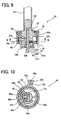
blade is disposed within the blade clamp.
Fig. 10 is a cross-sectional view taken along line X. X of Fig. 9.
Fig. 11 is a cross-sectional view taken along arrow A of Fig. 1, in which the collar
is disposed in a closed position.
Fig. 12 is a cross-sectional view taken along arrow A of Fig. 1, in which the collar
is disposed in an open position.
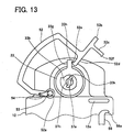
Fig. 13 is a cross-sectional view taken along arrow A of Fig. 1, in which the collar
is disposed in the blade locked position and a relatively thick blade is disposed in the blade
clamp.
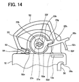
Fig. 14 is a cross-sectional view taken along arrow A of Fig. 1, in which the collar
is disposed in the blade locked position and a relatively thin blade is disposed in the blade
clamp.
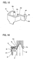
Fig. 15 is a perspective view of a representative collar.
Fig. 16 is an enlarged view of the portion within circle XVI shown in Fig. 2.
Fig. 17 is a side view of a representative blade.
Fig. 18 is a longitudinal cross-sectional view showing a blade clamp according to
the second representative embodiment.
Fig. 19 is a cross-sectional view taken along line XIX. XIX of Fig. 18.
Fig. 20 is a cross-sectional view taken along line XX. XX of Fig. 19.
Fig. 21 is a plan view showing a blade guide (sleeve) according to the second
representative embodiment.
Fig. 22 is a bottom view showing the blade clamp of Fig. 21.
Fig. 23(a) is a bottom view showing the blade clamp of Fig. 22 when the collar is
disposed in an open position and the blade guide (sleeve) is disposed in the blade
replacement position.
Fig. 23(b) shows the position of a cam surface when the collar is disposed in the
opened position and the blade guide (sleeve) is disposed in the blade replacement position.
Fig. 24(a) is a bottom view showing the blade clamp of Fig. 22 when the collar
and the blade guide (sleeve) are both disposed in a push start position.
Fig. 24(b) shows the position of the cam surface when the collar and the blade
guide (sleeve) arc both disposed in the push start position.
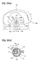
Fig. 25(a) is a bottom view showing the blade clamp of Fig. 22 when the collar
and the blade guide (sleeve) are both disposed in the blade locked position.
Fig. 25(b) shows the position of the cam surface when the collar and the blade
guide (sleeve) arc both disposed in the blade locked position.
Fig. 26(a) is a bottom view showing the blade clamp of Fig. 22 when the collar is
disposed in the closed position.
Fig. 26(b) shows the position of the cam surface when the collar is disposed in the
closed position.
In one embodiment of the present teachings, apparatus are taught for affixing a
blade having a pair of side projection to a drive shaft of a tool. For example, a rod may be
designed to be attached to a lower end of the drive shaft. The rod may have a blade slot
for receiving a base end of the blade so that the longitudinal axis of the blade aligns with a
longitudinal axis of the drive shaft. The rod also may have an aperture disposed
substantially perpendicular to the blade slot and communicating with the blade slot.
A blade guide (or sleeve) may be rotatably mounted on the rod. The blade guide
may include a blade opening and a blade slot that are designed to allow the blade
projections to pass therethrough. A cam surface may be defined on an inner surface of the
blade guide. A first stopper may project from one end of the cam surface or from the
outer surface of the rod, thereby defining a blade replacement position.
A pushpin (or pressing member) may be slidably disposed within the aperture of
the rod. The pushpin may include a head portion that slidably contacts the cam surface of
the blade guide. The position of the pushpin with respect to a direction perpendicular to
the longitudinal axis of the rod may be influenced by the rotational position of the cam
surface. The pushpin may contact the first stopper so as to prevent the blade guide from
pivoting beyond the blade replacement position.
A spring (e.g., a torsion spring) may bias the blade guide away from the blade
replacement position and toward an initial position (i.e., toward a blade locking or clamping
position). Optionally, a second stopper may project from a second end of the cam surface
or from the outer surface of the rod, thereby defining the initial position and the pivotal
range of the pushpin (and thus the blade guide). The second stopper may contact the
pushpin when a blade is not inserted in the blade guide in order to limit further pivotal
movement of the blade guide with respect to the rod. In another embodiment, the cam
surface may optionally be defined to prevent the pushpin from actively pressing the blade
when the blade guide pivots from the blade replacement position toward a push start
position. The push start position may be a predetermined angle displaced from the blade
replacement position. The cam surface then may preferably push or urge the pushpin
when the blade guide pivots past the push start position toward the blade locking position.
A friction angle may be defined between (1) a common normal at a contact point of the
cam surface and the pushpin and (2) a line passing through the contact point and the
rotational center of the cam surface. In one preferred embodiment, the friction angle from
the push start position to the blade locking position is between about 12-16°.
A portion of a rounded edge of the blade slot may be tapered in order to guide the
blade into the blade slot of the rod. Further, the pushpin may include a tapered surface
disposed so as to contact the blade as the blade is being inserted into the blade slot.
Optionally, the pushpin and rod aperture may be designed so that the pushpin does not
rotate within the rod aperture.
In another embodiment, a collar may be pivotally coupled to a housing of the tool.
The collar may include a tab (projection) designed for manual manipulation and a hook that
can engage a tab (projection) defined on the blade guide. Preferably, the collar hook will
engage the blade guide tab when the collar is rotated or pivoted in an opening direction so
as to cause the blade guide to rotate or pivot towards the blade replacement position.
Further, the collar hook preferably disengages from the blade guide tab when the collar is
disposed in a closed position.
In another embodiment of the present teachings, reciprocating power tools may
include a reciprocating drive shaft partially extending from a tool housing. A first end of
a rod may be attached to the drive shaft. A second end of the rod may include a first blade
slot defined to receive a blade so that a longitudinal axis of the blade aligns with a
longitudinal, reciprocating axis of the drive shaft. An aperture may be disposed
substantially perpendicular to the first blade slot and preferably communicates with the
blade slot.
A sleeve may be rotatably mounted on the rod. The sleeve may include a collar
engaging means defined on an outer surface of the sleeve. Preferably, the sleeve can pivot
between an initial position and a blade replacement position. A blade locking or clamping
position is defined between the initial position and the blade replacement position based in
part upon the thickness of the blade inserted into the first blade slot. A second blade slot
may be defined within the sleeve so as to prevent the blade from passing when the sleeve is
disposed in the blade locking position. Further, the second blade slot may be defined so as
to permit the blade to pass when the sleeve is disposed in the blade replacement position.
A cam surface may be defined on an inner surface of the sleeve.
A first stopper may project from either one end of the cam surface or from the rod.
In either case, the first stopper preferably defines the blade replacement position.
A pressing member or pushpin may be slidably disposed within the rod aperture.
The pressing member may include a contact portion that slidably contacts the cam surface.
Further, the cam surface preferably urges the pressing member further into the rod aperture
and the rod blade slot when the sleeve is pivoted toward the blade locking position. Also,
the pressing member preferably contacts the first stopper in the blade replacement position.
In this case, the sleeve is reliably preventing from pivoting beyond the blade replacement
position.
A collar may be pivotally coupled to the tool housing, so as to at least partially
surround the sleeve and the reciprocating drive shaft. A manually operable tab
(projection) may be formed on an outer surface of the collar. A sleeve engaging means
may be defined on an inner surface of the collar. Optionally, the collar engaging means
may engage the sleeve engaging means when the collar is manually pivoted in an opening
direction. In this case, the sleeve will pivot or rotate toward the blade replacement
position. Further, the collar engaging means preferably disengages from the sleeve
engaging means when the collar is relumed to a closed position. In that case, the sleeve
will not contact the collar during operation of the power tool.
Each of the additional features and method steps disclosed above and below may be
utilized separately or in conjunction with other features and method steps to provide
improved blade clamps and methods for making and using the same. Detailed
representative examples of the present teachings, which examples will be described below,
utilize many of these additional features and method steps in conjunction. However, this
dctailcd description is merely intended to teach a person of skill in the art further details for
practicing preferred aspects of the present teachings and is not intended to limit the scope
of the invention. Only the claims define the scope of the claimed invention. Therefore,
combinations of features and steps disclosed in the following detailed description may not
be necessary to practice the present teachings in the broadest sense, and are instead taught
merely to particularly describe representative and preferred embodiments of the present
teachings, which will be explained below in further detail with reference to the figures.
Of course, features and steps described in this specification and in the dependent claims
may be combined in ways that are not specifically enumerated in order to achieve other
novel embodiments of the present teachings and the present inventors contemplate such
additional combinations.
First Detailed Representative Embodiment
Fig. 1 shows a first detailed representative embodiment of a jigsaw 10 and blade
clamp 26 according to the present teachings. A housing 12 accommodates a motor (not
shown), which serves as a drive source, and a transmission mechanism (not shown), which
converts rotation of the motor into linear, or substantially linear, reciprocating motion of a
drive shaft (or spindle) 24. A power source cord 16 supplies power to the jigsaw 10 and
extends from the rear end of the housing 12. A handle 12a is defined along the upper
portion of the housing 12. A trigger switch 14 is disposed on an inner portion of the
handle 12a. The trigger switch 14 is actuated when pressed and current is supplied to the
motor when the switch 14 is actuated.
A base or shoe 18 is attached to the bottom of the housing 12. The underside 18a
of the base 18 is flat, or substantially flat, and supports the jigsaw 10 relative to a
workpiece that will be cut. A U-shaped opening is defined in the base 18 such that the
base 18 is open at the front. A blade 22 vertically reciprocates through the U-shaped
opening. In order to cut a workpiece, such as a piece of wood, the underside 18a of the
base 18 is pressed against the surface of the piece of wood and the jigsaw 10 is moved
forward.
A back roller 19 is disposed below the housing 12 and near the blade 22. A
groove (not shown) is formed around the cylindrical surface of the back roller 19. The
rear edge of the blade 22 fits within the groove. The back roller 19 receives a rearward
acting force applied by the blade 22 during a sawing operation.
A representative blade 22 will now be described in further detail. Fig. 17 shows
a side view of the blade 22, which includes a series of teeth 22a that serve to cut a
workpiece when the blade 22 vertically reciprocates. The upper end 22d of the blade 22
may have a trapezoidal shape and two projections (or dogs) 22b outwardly extend from the
blade 22. A recess 22c is defined adjacent to each respective projection 22b. When the
blade 22 is attached to the blade clamp 26, the projections 22b function to prevent the blade
22b from dislodging from the blade clamp 26, as will be further discussed below.
The blade 22 may have a variety of thickness, such as 0.9 mm, 1.8 mm, etc.
Generally speaking, the thickness of the blade 22 is selected according to the workpiece
that will be cut and according to the manner in which the sawing operation will be
performed, e.g., high speed sawing, fret sawing, etc. Thus, as further discussed below, the
present blade clamps can easily accommodate blades having a variety of thickness so that
the power tool can be utilized for a variety of applications.
The structure of the blade clamp 26, including a collar (or manipulation member or
release device) 52, will now be described in further detail with reference to Figures 2-16.
Blade clamp 26 is also generally known in the art as a "keyless" or "tool-less" blade clamp.
Because other portions of the jigsaw 10 may be constructed using known parts and
structures, description of such other portions is not required herein.
As shown in Fig. 2, the blade clamp 26 may be secured or affixed to the lower end
of the drive shaft 24. The blade clamp 26 preferably serves to secure or affix the
removable blade 22 to the drive shaft 24. The upper end of the drive shaft 24 may be
coupled to a transmission (not shown) disposed within the housing 12, as discussed above.
The transmission preferably generates the linear (or substantially linear) reciprocating
motion that is transmitted to the blade 22 via the drive shaft 24. The transmission also
may generate a reciprocating orbiting movement, as is well known in the art
Referring to Figs. 2-4, the blade clamp 26 may include a rod (or blade carrier) 37,
a pushpin 42, a torsion spring 44 and a blade guide (or sleeve) 33. In the present
specification, the terms "blade guide" and "sleeve" arc used interchangeably and no
difference in meaning is intended. Further, a pushpin is one type of pressing member (or
blade pressing means) and a torsion spring is one type of biasing member (or biasing
means) suitable for the present teachings. Fig. 2 shows the blade 22 mounted within the
blade clamp 26; Figs. 3 and 4 show the blade clamp 26 without the blade 22.
The base end of the rod 37 is secured to the lower end of the drive shaft 24. As
shown in Figs. 3 and 4, a rectangular-shaped blade slot (blade receiving portion) 37a is
defined in the rod 37. As shown in Fig. 3, the slot 37a extends upward from the lower end
of the rod 37 and the slot 37a is designed to receive the blade 22. That is, the slot 37a
extends along the longitudinal (or reciprocating) axis of the rod 37. As shown in Fig. 16,
a first end of a leaf spring (or plate spring) 62 may be disposed within the slot 37a and a
second end of the spring 62 may be disposed between a snap ring 35 and a flange 37k.
Upon insertion of the blade 22 into the slot 37a, the leaf spring 62 is compressed by the
upper face 22d of the blade 22 and then downwardly biases the blade 22. That is, spring
62 preferably biases the blade 22 in a direction that will eject the blade 22 from the blade
clamp 26. Further, as discussed below, when the blade guide 33 is disposed in the blade
locked position, the spring 62 biases the blade projections 22b against an upper surface of a
lower end 33b of the blade guide 33. Thus, the position of the blade 22 along the
longitudinal axis of the rod 37 is reliably secured.
Referring back to Figs. 3 and 4, a rectangular-shaped aperture 37b also may be
defined in the rod 37. The aperture 37b extends from the outer surface of the rod 37 into
the slot 37a. Because the pushpin 42 is inserted into or through the aperture 37b, the
cross-section of the pushpin 42 optionally may correspond to the cross-section of the
aperture 37b. In that case, the pushpin 42 can move perpendicular to the axis of the drive
shaft 24 (see Fig. 3), but the pushpin 42 will not rotate within the aperture 37b. Although
the cross-sections of the aperture 37b and pushpin 42 are preferably rectangular-shaped,
other polygonal shapes or substantially curved shapes (e.g., circular or oval) may be
advantageously utilized. In one optional embodiment, the aperture 37b slidably supports
movement of the pushpin 42 into and out of the slot 37a, but the (rotational) orientation of
the pushpin 42 does not change during operation.
The head 42b of the pushpin 42 preferably contacts a cam surface 33c of the blade
guide (sleeve) 33. When the cam surface 33c rotates towards the initial position (i.e.,
towards the blade locked position), the pushpin 42 is pushed or urged towards the slot 37a.
As shown in Fig. 4, the head 42b preferably includes contact portions 42a that outwardly
project from the pushpin 42 and extend in the direction of the periphery of the rod 37. As
shown in Fig. 3, an inclined plane 42c may be defined within the lower portion of the
pushpin 42. When the blade 22 is inserted into the slot 37a, the blade 22 will contact the
inclined plane 42c and push or urge the pushpin 42 back toward the cam surface 33c.
Therefore, the blade 22 can push the pushpin 42 out of the slot 37a, so that the blade 22 can
be inserted into the slot 37a.
Referring to Figs. 2 and 3, the blade guide 33 preferably is defined by a shape that
includes a substantially cylindrical large-diameter portion, which may contact a dust-resistant
cover 39 (described further below), and a substantially cylindrical small-diameter
portion, which may contact the blade 22. These two portions are preferably integrally
connected together in one piece and, as shown in Figs. 2 and 3, the large-diameter portion
is preferably disposed above the small-diameter portion.
Referring to Figs. 11-14, a round or circular aperture 33k and a rectangular slot 33f
are preferably defined in the lower end 33b of the blade guide 33. The slot 33f extends
across the round aperture 33k. The lower end 37n of the rod 37 is fitted into the round
aperture 33k and a clearance is defined between the rod 37 and the round aperture 33k.
Further, a flange 37k of the rod 37 is fitted into the blade guide 33 and a clearance is
defined between the flange 37k and the blade guide 33. Therefore, the blade guide 33 can
rotate or pivot about the rod 37 while still contacting the rod 37.
Referring to Fig. 3, a groove 33a is defined within the inner surface of the upper
portion of the blade guide 33. A snap ring 35 is fitted into the groove 33a, thereby
securely retaining the blade guide 33. The upper face 33m of the bottom of the blade
guide 33 contacts the lower end 37m of the rod 37. Therefore, the blade guide 33 is
mounted on the rod 37 such that axial movement of the blade guide 33 is restricted (i.e., the
blade guide 33 preferably does not move along the axial or longitudinal axis of the rod 37).
The underside of the snap ring 35 contacts the upper surface of the flange 37k. A
dust-resistant cover 39 is fitted onto the upper side of the snap ring 35 in order to seal the
gap between the rod 37 and the blade guide 33. The dust cover 39 may be made of an
elastic material, such as rubber or synthetic resin, thereby permitting the dust cover 39 to be
compressed between the rod 37 and the blade guide 33.
Referring to Fig. 4, a tab (or projection) 33g extends outwardly from the outer
peripheral surface of the blade guide 33. A key-shaped (or hook-shaped) extension (or
flange) 33h projects from the distal end of the tab 33g. As noted above, the cam surface
33c is defined on the inner surface of the blade guide 33 and the cam surface 33c is
disposed so as to be in sliding contact with the head 42b of the pushpin 42. Thus, the cam
surface 33c influences the position of the pushpin 42 in accordance with the angle of
rotation of the blade guide 33. That is, as the blade guide 33 rotates about the rod 37, the
cam surface 33c will push or urge the pushpin 42 into slot 37a in one rotating direction and
the cam surface 33c will allow the pushpin 42 to withdraw from slot 37a in the other
rotating direction. A first stopper 33e is formed at a first end of the cam surface 33c and a
second stopper 33d is formed at a second end of the cam surface 33c. Each stopper 33d,
33e projects towards the axis of the cam surface 33c and defines the angle of rotation of the
blade guide 33 with respect to the rod 37. Thus, the first stopper 33e preferably defines
the blade replacement position and the second stopper 33d preferably defines the initial
position, as will be further discussed below.
As shown in Fig. 3, a torsion spring 44 may be disposed around the rod 37. As
shown in Fig. 4, a first end 44a of the torsion spring 44 is inserted into a slot 33j defined
within the tab 33g of the blade guide 33. As shown in Fig. 3, a second end 44b of the
torsion spring 44 is inserted (biased) into a slot 37d defined within the rod 37.
Accordingly, the torsion spring 44 biases the blade guide 33 about the rod 37 in the
direction of arrow R, as shown in Fig. 4. When the second stopper 33d contacts the
contact portion 42a, the blade guide 33 is restricted to the position shown in Fig. 4.
Hereinafter, this position will referred to as "the initial position" of the blade guide 33. In
this state, the pushpin 42 projects into the slot 37a.
Referring back to Fig. 1, the collar 52 is pivotably mounted to a lower, front
portion of the housing 12. The collar 52 may be manually rotated or pivoted to move the
blade clamp 26 from the initial position (i.e., a position in which the pushpin 42 contacts
the second stopper 33d) or the blade locked position (i.e., a position in which blade
replacement is prohibited) to the blade replacement position (i.e., a position in which blade
replacement is permitted). The collar 52 optionally may be made of a translucent or a
transparent material.
Referring to Figs. 11 and 15, the collar 52 may have a substantially U-shaped
cross-scetion, although the shape of the collar 52 is not particularly restricted according to
the present teachings. Various designs may be utilized for the collar 52 as long as the
essential functions of the collar 52 are performed. A shaft hole 52a may be defined within
one end of the collar 52. A shaft 53 may be affixed to the housing 12 and inserted through
the shaft hole 52a. Thus, the collar 52 is pivotally attached to the housing 12 and can
rotate or turn about the shaft 53. Further, a torsion spring 54 may be disposed between the
collar 52 and the housing 12. Preferably, the torsion spring 54 biases the collar 52 in a
direction opposite to the arrow L shown in Fig. 11. Hereinafter, the direction of arrow L
will be referred to as an "opening direction" and the direction opposite of arrow L will be
referred to as a "closing direction."
A tab 52b, a lock portion 52c, and a hook portion 52d are preferably defined at the
opposite end of the collar 52 from the shaft hole 52a. The tab 52b extends or projects
outwardly in order to permit an operator to pivot or rotate the collar 52 about the shaft 53.
The hook portion 52d extends in an opposite direction (inward direction) with respect to the
tab 52b. A key-like portion 52e is formed at the terminal end of the hook portion 52d.
When the collar 52 is pivoted or rotated in the opening direction, the key portion 33h of tab
33g will catch or engage the key portion 52e. Accordingly, the blade guide 33 will turn or
rotate together with the collar 52. The lock portion 52c projects from the tab 52b toward
the housing 12. Another key portion 52f is formed at the terminal end of the lock portion
52c. The housing 12 further includes a stopper 12e and a lock member 58. Another key
portion 58a is formed at the terminal end of the lock member 58.
When the operator releases the collar 52, the torsion spring 54 will bias the collar
52 in the closing direction. In that case, the collar 52 will contact the stopper 12e of the
housing 12 and the key portion 52f of the collar 52 will engage the key portion 58a of the
lock member 58. Therefore, lock member 58 will lock the collar 52 in position with
respect to the housing 12 and the collar 52 can be reliably secured to the housing 12 during
a sawing operation. In order to unlock the collar 52, a force that is greater than the biasing
force of the torsion spring 54 must be applied to the collar 52 so as to disengage the keys
52f, 58a. Hereinafter, the position where the collar 52 contacts the stopper 12e will be
referred to as the closed position of the collar 52.
A representative method for operating the blade clamp 26 will now be discussed.
Before the blade 22 is inserted into and attached to the blade clamp 26, the collar 52 may be
locked in the closed position by the lock member 58, as is shown in Fig. 11. Also, in the
initial position as shown in Fig. 4, the second stopper 33d of the blade guide 33 contacts the
contact portion 42a of the pushpin 42. Thus, a clearance exists between the tab 33g of the
blade guide 33 and the hook portion 52d of the collar 52, as shown in Fig. 11.
In order to affix the blade 22 to the drive shaft 24 via the blade clamp 26, the collar
52 is rotated or pivoted in the opening direction L. For example, the operator may
manually rotate or pivot the collar 52 about the shaft 53. By applying a force to the tab
52b, the lock portion 52c of the collar 52 will disengage from the lock member 58 of the
housing 12 so as to permit the collar 52 to rotate or pivot in the opening direction L.
Therefore, the hook portion 52d of the collar 52 will contact the tab 33g of the blade guide
33. By further applying a rotating force (torque) to the collar 52, the hook portion 52d
will continue to contact the tab 33g. Consequently, the blade guide 33 will rotate as the
key portion 52c of the hook portion 52d catches or engages the key portion 33h of the tab
33g. Therefore, the hook portion 52d is prevented from separating from the tab 33g while
the blade guide 33 is rotating or pivoting.
When the blade guide 33 pivots to a predetermined angle, the first stopper 33e of
the cam surface 33c will contact the contact portion 42a of the pushpin 42 and
consequently, the blade guide 33 is prevented from further pivoting, as shown in Figs. 5 and
6. Moreover, when the first stopper 33e contacts the contact portion 42a, the slot 33f of
the blade guide 33 aligns with the slot 37a of the rod 37, as shown in Fig. 12. That is, the
slot 33f of the blade guide 33 extends beyond both ends of the slot 37a of the rod 37,
thereby providing a longer slot. The width of the slot defined by the rod 37 and blade
guide 33 is slightly longer than the width W of the blade 22. As shown in Fig. 17, width
W is defined as the distance from the side edge of one projection 22b to the side edge of the
other projection 22b. As a result, the blade 22 can be easily inserted into the blade slot
defined by the blade guide 33 and rod 37.
When the blade guide 33 is disposed in this blade replacement position, the blade
22 can be inserted into or removed from the blade clamp 26. If a blade is inserted in the
blade guide 33 when the blade guide is rotated or pivoted to the blade replacement position,
the leaf spring 62 will automatically bias or push the blade 22 out of the blade guide 33
without requiring operator assistance. Therefore, the operator is not required to touch the
blade 22 in order to remove the blade 22, which is particularly advantageous if the jigsaw
10 has been recently operated and the blade 22 is hot.
When the blade guide 33 is pivoted or rotated to the blade replace ment position
from the initial position (or the blade locked position), the cam surface 33c formed in the
blade guide 33 pivots or rotates at the same time. Therefore, the cam surface 33c will
separate from the head 42b of the pushpin 42, as indicated in Figs. 5 and 6.
When the blade guide 33 is disposed in the blade replacement position and the
blade 22 is inserted into the slot 37a, the base end upper face 22d of the blade 22 will
contact the inclined plane 42c of the pushpin 42. The pushpin 42 will therefore move
toward the cam surface 33c. When the blade 22 is further inserted into the slot 37a, the
upper face 22d of the blade 22 will lift and deform the leaf spring 62 in order to contact the
inner surface of the slot 37a, as is shown in Fig. 16. Therefore, opposing forces act on the
blade 22.
After the blade 22 has been inserted into the blade clamp 26, the force (torque)
applied to the collar 52 is reduced or withdrawn (i.e., the collar 52 is manually released).
In that case, the blade guide 33 will automatically return to the blade locked position due to
the biasing force of the torsion spring 44. Therefore, the slot 33f of the blade guide 33
will no longer align with the slot 37a of the rod 37. Accordingly, as shown in Fig. 2, the
projections 22b of the blade 22 will contact the upper surface of the lower end 33b of the
blade guide 33, thereby preventing the blade 22 from being removed from the blade clamp
26.
As noted above, the cam surface 33c rotates together with the blade guide 33. As
a result, when the blade guide 33 rotates or pivots towards the blade locked position, the
cam surface 33c will push or urge the pushpin 42 toward the side surface of the blade 22.
Therefore, the blade 22 will be securely retained between the pushpin 42 and a wall 37j
defining a portion of the slot 37a, as shown in Figs. 7 to 10. Because the blade 22 is
firmly fixed or secured in position in such a manner, no clearance or space exists between
the blade 22 and the rod 37.
As mentioned above, the blade 22 is secured to the blade clamp 26 by being tightly
held between the pushpin 42 and the wall 37j. Therefore, even if the thickness of the
blade 22 varies, the blade 22 can be reliably secured to the rod 37. Figs. 7 and 8 show a
relatively thin blade 22 (c.g., a blade thickness of 0.9 mm) that is firmly fixed in position.
Figs. 9 and 10 show a relatively thick blade 22 (e.g., a blade thickness of 1.8 mm) that is
firmly fixed in position. Thus, as noted above, the present blade clamps can be
advantageously utilized with blades of varying thickness.
When the blade 22 is firmly fixed in the blade locking position, the head 42b of
the pushpin 42 projects beyond the periphery of the rod 37, as compared to the state in
which the blade guide 33 is in the initial position. Therefore, the blade guide 33 i s
restricted or prevented from pivoting past the blade locking position (i.e., toward the initial
position) when the head 42b of the pushpin 42 contacts the cam surface 33c of the blade
guide 33. Accordingly, the blade guide 33 will rotate or pivot toward the initial position
(and the blade locked position) together with the collar 52 and the blade guide 33 will stop
in either of the representative blade locking positions shown in Fig. 13 and 14. Fig. 13
shows a relatively thick blade that is affixed to the drive shaft 24 by the blade clamp 26 and
Fig. 14 shows a relatively thin blade that is affixed to the drive shaft 24 by the blade clamp
26. Thus, the blade locked position of the blade guide 33 will be determined by the
thickness of the blade 22 that has been inserted into slot 37a.
However, because the torsion spring 54 biases the collar 52, the collar 52 will
return to the closed position (shown in Fig. 11) from the positions shown in Fig. 13 and 14.
That is, the collar 52 will separate or disengage from the blade guide 33 so that the collar
52 can return to the closed position, regardless of the rotational position of the blade guide
33. Therefore, the blade clamp 26 can freely reciprocate during a sawing operation
without contacting the collar 52. Further, the collar 52 will protect the blade clamp 26
during a sawing operation and the collar 52 will also protect the operator's hands from
injury due to the reciprocating blade clamp 26.
In order to remove the blade 22 from the blade clamp 26, the collar 52 can be
rotated or pivoted in the opening direction (arrow L shown in Fig. 11), so as to cause the
blade guide 33 to rotate or pivot towards the blade replacement position. By rotating the
blade guide 33 towards the blade replacement position, the cam surface 33c stops actively
pressing or urging the pushpin 42 against the side surface of the blade 22. Therefore, the
blade 22 will be unlocked and is free to be removed. When the blade guide 33 is disposed
in the blade replacement position, the slot 33f of the blade guide 33 aligns with the slot 37a
of the rod 37 and the projections 22b of the blade 22 can pass through the aligned slots 33f,
37a. Thus, the blade 22 can be easily removed from the blade clamp 26. In addition, as
noted above, the biasing force of the leaf spring 62 acts on the blade 22 and the blade 22
will be automatically pushed out of or ejected from the blade clamp 26 when the blade
guide 33 is rotated to the blade replacement position.
Therefore, in the blade clamp 26 according to the first representative embodiment,
the first stopper 33c of the cam surface 33c of the blade guide 33 will contact the contact
portion 42a of the pushpin 42 and restrict the blade guide 33 from further pivoting or
rotating past the blade replacement position (i.c., the position in which the slots 33f, 37a are
aligned). Consequently, the blade guide 33 can be reliably positioned in the blade
replacement position. Therefore, by improving the precision of the blade guide 33, the
rod 37 and the pushpin 42, the blade guide 33 can be more accurately positioned in the
blade replacement position. However, because the collar 52 is not utilized for positioning
the blade guide 33 in the blade replacement position, no special measures are required to be
taken with respect to the collar 52 or the housing 12, which is a significant advantage over
the prior art blade clamp that was described above.
Further, when the collar 52 is disposed in its closed position and the blade guide
33 is disposed in its initial position or the blade locked position, the collar 52 does not
contact the blade guide 33. Thus, even if the trigger switch 14 is mistakenly or
accidentally turned ON (actuated) without the blade 22 being attached to the blade clamp
26, the collar 52 and the blade clamp 26 will not be damaged due to the reciprocating
movement of the drive shaft 24.
In addition, when the blade guide 33 is pivoted or rotated to the blade replacement
position with the blade 22 secured within the blade clamp 26, the leaf spring 62
automatically pushes or ejects the blade 22 from the blade clamp 26. Therefore, the blade
detachment or removal operation can be accomplished without directly touching the blade
22 or the blade clamp 26, which may be hot due to heat generated during a sawing
operation. Thus, the operator can safely remove the blade 22 without injury.
Furthermore, when the collar 52 is disposed in the closed position, the blade clamp
26 is enclosed or surrounded (and thereby protected) by the collar 52. Therefore, the
operator is prevented from accidentally touching the blade clamp 26, which will
reciprocally move during a sawing operation. Further, the collar 52 prevents saw dust or
other materials from the workpiece from being scattered. Moreover, if the collar 52 is
made of a translucent or transparent material, the operator can see the blade 22 while the
workpiece is being cut.
In the above-described embodiment, the first and second stoppers 33e, 33d and the
pushpin 42 restrict or limit the pivotal range of the blade guide 33 relative to the rod 37,
because the first stopper 33e is formed at one end of the cam surface 33c and the second
stopper 33d is formed at the other end of the cam surface 33c. However, the present
teachings are not limited to such an arrangement and may be modified in various ways.
For example, the blade guide 33 may include stoppers and the rod 37 may include a contact
portion that is designed to contact the stoppers. When a stopper of the blade guide 33
contacts a contact portion of the rod 37, the blade guide 33 will be restricted from pivoting
relative to the rod 37.
Second Detailed Representative Embodiment
Similar to the blade clamp 26 of the first representative embodiment, the blade
clamp 110 of the second representative embodiment may include a rod 112, a pushpin 113
and a blade guide 115, as shown in Fig. 18. The rod 112 and pushpin 113 employed in the
second representative embodiment may have substantially the same structure as the rod 37
and pushpin 42 employed in the first representative embodiment. Therefore, only the
portions of the blade guide 115 that differ from the blade guide 33 of the first representative
embodiment will now be described.
As shown in Fig. 21, an aperture 115b is preferably defined in the bottom 115a of
the blade guide 115 by a combination of a round opening 115f and a pair of rectangular-shaped
slots 115g. Specifically, the aperture 115b may include four comers where arc-shaped
portions of the round opening 115f respectively adjoin the adjacent slots 115g,
which slots 115g radially extend from the round opening 115f. Two diagonally opposing
comers, as indicated by lines in Fig. 21, may be chamfered in order to define inclined
planes 115h. That is, each radial slot 115g may have one tapered side.
The round opening 115f has a diameter that corresponds to the diameter of the
lower end 112c of the rod 112, which lower end 112c is shown in Fig. 19. The diameter of
the round opening 115f is slightly greater than the width of the indentations or recesses 22c
of the blade 22, which recesses 22c are shown in Fig. 17. The distance between the distal
end of a first slot 115g and the distal end of a second slot 115g (i.e., the length of aperture
115b in the radial direction) is slightly greater than the widest portion of the blade 22.
Naturally, the distance between the side edge of the one projection 22b and the side edge of
the other projection 22b is the widest portion of the blade 22, as shown in Fig. 17.
Therefore, the inclined planes 115h guide the blade 22 into an appropriate position within
the slot 112a of the rod 112, even if the blade 22 is obliquely inserted into the slot 112a.
This feature of the second representative embodiment will be further described below.
Fig. 21 shows the shape of a cam surface 116 of the blade guide 115. The cam
surface 116 includes a first cam face 116a, which covers the range indicated by reference
mark C1, and a second cam face 116b, which covers the range indicated by reference mark
C2. The first cam face 116a and the second cam face 116b form a continuous cam face or
surface. Thus, the first cam face 116a will push the pushpin 113 according to the distance
between the central or rotational axis of the blade guide 115 and the first cam face 116a.
This distance naturally will vary as the blade guide 115 pivots or rotates. On the other
hand, the second cam face 116b will not actively push or urge the pushpin 113, because the
distance from the central or rotational axis of the blade guide 115 to the second cam face
116b is constant. A stopper 116d may be formed at the end of the second cam face 116b
and may project generally in the direction of the central or rotational axis of the blade guide
115.
Referring to Figs. 18 and 19, a dust cover 119 may be fitted onto the upper end of
the blade guide 115 and the dust cover 119 may be made of an elastic material, such as
rubber or synthetic resin. In the second representative embodiment, an outer peripheral
groove 112h having a rectangular cross-section is defined within the rod 112. Thus, the
inner peripheral edge 119a of the dust cover 119 is pressed into the groove 112h and the
dust cover 119 is prevented from being pulled out along the axial direction (i.e., vertically
as shown in Fig. 19).
The surface of the blade guide 115 may be nickel-plated in order to increase
surface hardness and smoothness and decrease frictional resistance, as compared to other
rust-proofing treatments (e.g., chromate treatment and galvanization). Accordingly,
smooth pivoting of the blade guide 115 is ensured during rotation. Also, as described in
the first representative embodiment, the pushpin 113 may include a tapered edge 113b for
pushing the pushpin 113 out of the rod aperture 112b when the blade 22 is inserted through
slot 112a.
A representative method for operating the blade clamp 110 having the above
structure will now be discussed. Fig. 22 shows a bottom view of the blade clamp 110
without the blade 22. In this state, the torsion spring 118 (shown in Fig. 19) biases the
blade guide 115 in the direction of arrow L as shown in Fig. 20. The cam surface 116 of
the blade guide 115 can not push the pushpin 113 further forward, thereby prohibiting the
blade guide 115 from further pivoting in the direction of arrow L as shown in Fig. 20.
Thus, in this representative embodiment, a second stopper is not required to define the
initial position. Moreover, in this initial position, the blade 22 can not pass through the
slot 112a, because the pushpin 113 is blocking the slot 112a, as shown in Fig. 22.
In order to attach the blade 22 to the blade clamp 110, a tab 130b of a collar 130
may be manually pushed or rotated in the opening direction (i.e., the direction opposite to
arrow L in Fig. 20). As a result, the collar 130 will pivot or rotate about a shaft 102b until
a projection 115d of the blade guide 115 catches or engages a hook 130c. As shown in
Fig. 23(a), when more force (torque) is applied to the collar 130 in the opening direction,
the blade guide 115 will rotate or pivot towards the blade replacement position together
with the collar 130 against biasing force of the torsion spring 118. As shown in Fig.
23(b), in the blade replacement position, the pushpin 113 contacts the stopper 116d of the
cam surface 116 so as to restrict further rotation of the blade guide 115.
In the blade replacement position, the slots 115g extending from the round opening
115b are in alignment with the slot 112a. When the blade 22 is inserted into the slot 112a,
the projections 22b of the blade 22 pass through the bottom 115a of the blade guide 115 via
the aperture 115b. Thus, the base end of the blade 22 is accommodated within the slot
112a. At this time, the inclined planes (or tapered planes) 115h, which are defined by the
round opening 115b, facilitate insertion of the blade 22 into the slot 112a.
Then, the manual pressure or force being applied to the collar 130 is reduced or
released while the base end of the blade 22 is kept sufficiently inserted in the slit 112a. As
a result, the biasing force of the torsion spring 118 will turn or rotate the blade guide 115
and the collar 130 back to a "push start" position, as shown in Figs. 24(a) and 24(b). As
mentioned above, the radius of the second cam face 116b is constant with respect to the
pushpin 113. Therefore, when the blade guide 115 rotates from the blade replacement
position to the push start position, the second cam face 116b does not actively apply any
force to the pushpin 113 in the direction perpendicular to the longitudinal axis of the blade
22.
In the push start position, the projections 22b are respectively moved away from
the slots 115g and arc supported (blocked) by the upper surface of the bottom 115a of the
blade guide 115. Accordingly, the projections 22b are securely supported by the blade
guide 115 and the blade 22 will not fall or drop out of the blade clamp 110. As noted
above, between the blade replacement position and the push start position, the pushpin 113
does not actively apply any force to the blade 22. Furthermore, even if the blade 22 is
obliquely inserted into the slot 112a, the blade 22 will be guided into the appropriate
position within the slot 112a with the aid of the inclined planes 115h, which are defined by
the round opening 115f. Therefore, the blade guide 115 can reliably rotate or pivot to a
position that will hold the blade 22 within the blade clamp 110 without falling out.
Consequently, the operator is not required to hold the blade 22 until the blade guide 115
reaches the blade locked position.
Subsequently, the blade guide 115 and the collar 130 are returned to the blade lock
position (shown in Figs. 25(a) and 25(b)) due to the biasing force of the torsion spring 118.
During this portion of the rotation, the first cam face 116a will slidingly contact the pushpin
113 and push or urge the pushpin 113 in a direction perpendicular to the rotational axis.
The pushpin 113 will press the blade 22 against one inner wall defining the slot 112a.
Thus, the pushpin 113 can not be moved further forward than this inner wall and the pivotal
position of the blade guide 115 in the closing direction is restricted. Thus, the blade guide
115 is locked in position and the blade 22 is securely retained within the slot 112a. This
feature of the second representative embodiment enables the blade clamp 110 to securely
clamp or lock blades of various thickness.
Figs. 24(b) and 25(b) each show an angle F, or a friction angle, of the first cam
face 116a. The friction angle F of the first cam face 116a is an angle defined between a
common tangent Lt at the contact point P of the first cam face 116a and the head of the
pushpin 113 and a straight line Lv that is perpendicular to a line passing through the contact
point P and the rotational axis. The friction angle F preferably is between about 12-16°,
thereby guaranteeing sufficient clamping force for the blade 22 within the pivotal range of
the first cam face 116a (i.e., the range C1 shown in Fig. 21). Thus, after rotating past the
push start position, the first cam face 116a applies more force against the pushpin 113 and
thus the blade 22 in order to securely clamp the blade 22 within the blade clamp 110.
After the state shown in Figs. 25(a) and 25(b), the pushpin 113 is not further
displaced, thereby maintaining the blade guide 115 in the blade locked position. However,
the collar 130 will disengage from the blade guide 115 and return to the closed position
shown in Figs. 26(a) and 26(b). Therefore, in the closed position, the collar 130 does not
contact the blade guide 115 and the blade 22 is reliably attached to the drive shaft 24.
In the above embodiments, although relatively thin blades 22 were utilized, any
blade that can be inserted into the slot 112a can be used, even if the thickness of the blade
22 leaves almost no space within the slot 112a.
Moreover, as should be clear from the above description, the blade guide 115 of
the jigsaw according to the second representative embodiment can easily pivot from the
blade replacement position to the push start position, regardless of the thickness of the
blade 22. Accordingly, the projections 22b of the blade 22 will be securely locked within
the blade guide 115.