EP1236519A1 - Vorrichtung und Verfahren um eine Substanz mit einem fokussierten Strahl auf einem Substrat aufzubringen - Google Patents
Vorrichtung und Verfahren um eine Substanz mit einem fokussierten Strahl auf einem Substrat aufzubringen Download PDFInfo
- Publication number
- EP1236519A1 EP1236519A1 EP02075633A EP02075633A EP1236519A1 EP 1236519 A1 EP1236519 A1 EP 1236519A1 EP 02075633 A EP02075633 A EP 02075633A EP 02075633 A EP02075633 A EP 02075633A EP 1236519 A1 EP1236519 A1 EP 1236519A1
- Authority
- EP
- European Patent Office
- Prior art keywords
- functional material
- discharge device
- fluid
- receiver
- supercritical fluid
- Prior art date
- Legal status (The legal status is an assumption and is not a legal conclusion. Google has not performed a legal analysis and makes no representation as to the accuracy of the status listed.)
- Ceased
Links
- 0 *C=C1CCCC1 Chemical compound *C=C1CCCC1 0.000 description 1
Images


Classifications
-
- B—PERFORMING OPERATIONS; TRANSPORTING
- B05—SPRAYING OR ATOMISING IN GENERAL; APPLYING FLUENT MATERIALS TO SURFACES, IN GENERAL
- B05D—PROCESSES FOR APPLYING FLUENT MATERIALS TO SURFACES, IN GENERAL
- B05D1/00—Processes for applying liquids or other fluent materials
- B05D1/02—Processes for applying liquids or other fluent materials performed by spraying
- B05D1/025—Processes for applying liquids or other fluent materials performed by spraying using gas close to its critical state
-
- B—PERFORMING OPERATIONS; TRANSPORTING
- B05—SPRAYING OR ATOMISING IN GENERAL; APPLYING FLUENT MATERIALS TO SURFACES, IN GENERAL
- B05B—SPRAYING APPARATUS; ATOMISING APPARATUS; NOZZLES
- B05B7/00—Spraying apparatus for discharge of liquids or other fluent materials from two or more sources, e.g. of liquid and air, of powder and gas
- B05B7/24—Spraying apparatus for discharge of liquids or other fluent materials from two or more sources, e.g. of liquid and air, of powder and gas with means, e.g. a container, for supplying liquid or other fluent material to a discharge device
- B05B7/26—Apparatus in which liquids or other fluent materials from different sources are brought together before entering the discharge device
- B05B7/28—Apparatus in which liquids or other fluent materials from different sources are brought together before entering the discharge device in which one liquid or other fluent material is fed or drawn through an orifice into a stream of a carrying fluid
- B05B7/32—Apparatus in which liquids or other fluent materials from different sources are brought together before entering the discharge device in which one liquid or other fluent material is fed or drawn through an orifice into a stream of a carrying fluid the fed liquid or other fluent material being under pressure
-
- C—CHEMISTRY; METALLURGY
- C23—COATING METALLIC MATERIAL; COATING MATERIAL WITH METALLIC MATERIAL; CHEMICAL SURFACE TREATMENT; DIFFUSION TREATMENT OF METALLIC MATERIAL; COATING BY VACUUM EVAPORATION, BY SPUTTERING, BY ION IMPLANTATION OR BY CHEMICAL VAPOUR DEPOSITION, IN GENERAL; INHIBITING CORROSION OF METALLIC MATERIAL OR INCRUSTATION IN GENERAL
- C23C—COATING METALLIC MATERIAL; COATING MATERIAL WITH METALLIC MATERIAL; SURFACE TREATMENT OF METALLIC MATERIAL BY DIFFUSION INTO THE SURFACE, BY CHEMICAL CONVERSION OR SUBSTITUTION; COATING BY VACUUM EVAPORATION, BY SPUTTERING, BY ION IMPLANTATION OR BY CHEMICAL VAPOUR DEPOSITION, IN GENERAL
- C23C4/00—Coating by spraying the coating material in the molten state, e.g. by flame, plasma or electric discharge
- C23C4/12—Coating by spraying the coating material in the molten state, e.g. by flame, plasma or electric discharge characterised by the method of spraying
- C23C4/123—Spraying molten metal
-
- B—PERFORMING OPERATIONS; TRANSPORTING
- B05—SPRAYING OR ATOMISING IN GENERAL; APPLYING FLUENT MATERIALS TO SURFACES, IN GENERAL
- B05D—PROCESSES FOR APPLYING FLUENT MATERIALS TO SURFACES, IN GENERAL
- B05D2401/00—Form of the coating product, e.g. solution, water dispersion, powders or the like
- B05D2401/90—Form of the coating product, e.g. solution, water dispersion, powders or the like at least one component of the composition being in supercritical state or close to supercritical state
-
- Y—GENERAL TAGGING OF NEW TECHNOLOGICAL DEVELOPMENTS; GENERAL TAGGING OF CROSS-SECTIONAL TECHNOLOGIES SPANNING OVER SEVERAL SECTIONS OF THE IPC; TECHNICAL SUBJECTS COVERED BY FORMER USPC CROSS-REFERENCE ART COLLECTIONS [XRACs] AND DIGESTS
- Y10—TECHNICAL SUBJECTS COVERED BY FORMER USPC
- Y10S—TECHNICAL SUBJECTS COVERED BY FORMER USPC CROSS-REFERENCE ART COLLECTIONS [XRACs] AND DIGESTS
- Y10S977/00—Nanotechnology
- Y10S977/70—Nanostructure
- Y10S977/773—Nanoparticle, i.e. structure having three dimensions of 100 nm or less
Definitions
- This invention relates generally to deposition and etching technologies and, more particularly, to a technology for delivering a collimated and/or focused beam of functional materials dispersed and/or dissolved in a compressible fluid that is in a supercritical or liquid state and becomes a gas at ambient conditions, to create a high-resolution pattern or image onto a receiver.
- deposition technologies are typically defined as technologies that deposit functional materials dissolved and/or dispersed in a fluid onto a receiver (also commonly referred to as a substrate, etc.) to create a pattern.
- Etching technologies are typically defined as technologies that create a specific pattern on a receiver through the selective alteration of portions of the receiver by delivering materials dissolved and/or dispersed in a fluid onto the receiver to physically remove selective portions of the receiver and/or chemically modify the receiver.
- a non-colloidal ballistic aerosol is formed prior to exiting the print head.
- This non-colloidal ballistic aerosol which is a combination of the functional material and the propellant, is not thermodynamically stable/metastable. As such, the functional material is prone to settling in the propellant stream which, in turn, can cause functional material agglomeration leading to nozzle obstruction and poor control over functional material deposition.
- An object of the present invention is to provide a technology that permits high speed, accurate, and precise deposition of a functional material on a receiver.
- Another object of the present invention is to provide a technology that permits functional material deposition of ultra-small particles.
- Another object of the present invention is to provide a technology that permits high speed, accurate, and precise patterning of a receiver that permits the creation of ultra-small features on the receiver.
- Another object of the present invention is to provide a self-energized, self-cleaning technology capable of controlled functional material deposition in a format that is free from receiver size restrictions.
- Another object of the present invention is to provide a technology that permits high speed, accurate, and precise patterning of a receiver that can be used to create high resolution patterns on the receiver.
- Yet another object of the present invention is to provide a technology that permits high speed, accurate, and precise patterning of a receiver having reduced functional material agglomeration characteristics.
- Yet another object of the present invention is to provide a technology that permits high speed, accurate, and precise patterning of a receiver using a mixture of functional material and dense fluid that is thermodynamically stable/metastable.
- Yet another object of the present invention is to provide a technology that permits high speed, accurate, and precise patterning of a receiver that has improved material deposition capabilities.
- an apparatus for focusing a functional material includes a pressurized source of fluid in a thermodynamically stable mixture with a functional material.
- a discharge device having an inlet and an outlet is connected to the pressurized source at the inlet.
- the discharge device is shaped to produce a collimated beam of functional material, where the fluid is in a gaseous state at a location before or beyond the outlet of the discharge device.
- the fluid can be one of a compressed liquid and a supercritical fluid.
- the thermodynamically stable mixture includes one of the functional material being dispersed in the fluid and the functional material being dissolved in the fluid.
- a method of focusing a functional material includes providing a pressurized source of fluid in a thermodynamically stable mixture with a functional material; and causing the functional material to collimate.
- an apparatus for focusing a functional material includes a pressurized source of fluid in a thermodynamically stable mixture with a functional material.
- a discharge device having an inlet and an outlet is connected to the pressurized source at the inlet.
- the discharge device has a variable area portion and a constant area portion with a collimated beam of functional material being produced as the mixture moves from the inlet of the discharge device through the outlet of the discharge device and the fluid being in a gaseous state at a location relative to the discharge device.
- the location can be positioned within a region of the discharge device or positioned in a region beyond the discharge device.
- a method of focusing a functional material includes providing one of a compressed liquid and a supercritical fluid in a first predetermined thermodynamic state; adding a functional material to one of the compressed liquid and the supercritical fluid; and moving the functional material and one of the compressed liquid and the supercritical fluid to a second thermodynamic state, whereby one of the compressed liquid and the supercritical fluid evaporates allowing the functional material to release in a collimated beam.
- moving one of the compressed liquid and the supercritical fluid and the functional material to a second thermodynamic state can include focusing the functional material.
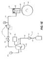
- delivery system 10 has components, 11, 12, and 13 that take chosen solvent and/or dispersant materials to a compressed liquid and/or supercritical fluid state, make a solution and/or dispersion of an appropriate functional material or combination of functional materials in the chosen compressed liquid and/or supercritical fluid, and deliver the functional materials as a collimated and/or focused beam onto a receiver 14 in a controlled manner.
- Functional materials can be any material that needs to be delivered to a receiver, for example electroluminescent materials, imaging dyes, ceramic nanoparticles etc., to create a pattern on the receiver by deposition, etching, coating, other processes involving the placement of a functional material on a receiver, etc.
- the chosen materials taken to a compressed liquid and/or supercritical fluid state are gases at ambient pressure and temperature.
- Ambient conditions are preferably defined as temperature in the range from-100 to +100 °C, and pressure in the range from 1x10 -8 - 100 atm for this application.
- FIG. 1A a schematic illustration of the delivery system 10 is shown.
- the delivery system 10 has a compressed liquid/supercritical fluid source 11, a formulation reservoir 12, and a discharge device 13 connected in fluid communication along a delivery path 16.
- the delivery system 10 can also include a valve or valves 15 positioned along the delivery path 16 in order to control flow of the compressed liquid/supercritical fluid.
- a compressed liquid/supercritical fluid carrier, contained in the compressed liquid/supercritical fluid source 11, is any material that dissolves/solubilizes/disperses a functional material.
- the compressed liquid/supercritical fluid source 11 delivers the compressed liquid/supercritical fluid carrier at predetermined conditions of pressure, temperature, and flow rate as a supercritical fluid, or a compressed liquid.
- Materials that are above their critical point, defined by a critical temperature and a critical pressure, are known as supercritical fluids.
- the critical temperature and critical pressure typically define a thermodynamic state in which a fluid or a material becomes supercritical and exhibits gas like and liquid like properties. Materials that are at sufficiently high temperatures and pressures below their critical point are known as compressed liquids.
- Materials in their supercritical fluid and/or compressed liquid state that exist as gases at ambient conditions find application here because of their unique ability to solubilize and/or disperse functional materials of interest in the compressed liquid or supercritical state.
- Fluid carriers include, but are not limited to, carbon dioxide, nitrous oxide, ammonia, xenon, ethane, ethylene, propane, propylene, butane, isobutane, chlorotrifluoromethane, monofluoromethane, sulphur hexafluoride and mixtures thereof. Due its characteristics, e.g. low cost, wide availability, etc., carbon dioxide is generally preferred in many applications.
- the formulation reservoir 12 is utilized to dissolve and/or disperse functional materials in compressed liquids or supercritical fluids with or without dispersants and/or surfactants, at desired formulation conditions of temperature, pressure, volume, and concentration.
- the combination of functional material and compressed liquid/supercritical fluid is typically referred to as a mixture, formulation, etc.
- the formulation reservoir 12 can be made out of any suitable materials that can safely operate at the formulation conditions.
- An operating range from 0.001 atmosphere (1.013 x 10 2 Pa) to 1000 atmospheres (1.013 x 10 8 Pa) in pressure and from -25 degrees Centigrade to 1000 degrees Centigrade is generally preferred.
- the preferred materials include various grades of high pressure stainless steel. However, it is possible to use other materials if the specific deposition or etching application dictates less extreme conditions of temperature and/or pressure.
- the formulation reservoir 12 should be precisely controlled with respect to the operating conditions (pressure, temperature, and volume).
- the solubility/dispersibility of functional materials depends upon the conditions within the formulation reservoir 12. As such, small changes in the operating conditions within the formulation reservoir 12 can have undesired effects on functional material solubility/dispensability.
- any suitable surfactant and/or dispersant material that is capable of solubilizing/dispersing the functional materials in the compressed liquid/supercritical fluid for a specific application can be incorporated into the mixture of functional material and compressed liquid/supercritical fluid.
- Such materials include, but are not limited to, fluorinated polymers such as perfluoropolyether, siloxane compounds, etc.
- FIGS. 1B-1D alternative embodiments of the invention shown in FIG. 1A are described.
- individual components are in fluid communication, as is appropriate, along the delivery path 16.
- a pressure control mechanism 17 is positioned along the delivery path 16.
- the pressure control mechanism 17 is used to create and maintain a desired pressure required for a particular application.
- the pressure control mechanism 17 can include a pump 18, a valve(s) 15, and a pressure regulator 19a, as shown in FIG. 1B.
- the pressure control mechanism 17 can include a pump 18, a valve(s) 15, and a multi-stage pressure regulator 19b, as shown in FIG. 1C.
- the pressure control mechanism can include alternative combinations of pressure controlling devices, etc.
- the pressure control mechanism 17 can include additional valve(s) 15, actuators to regulate fluid/formulation flow, variable volume devices to change system operating pressure, etc., appropriately positioned along the delivery path 16.
- the pump 18 is positioned along the delivery path 16 between the fluid source 11 and the formulation reservoir 12.
- the pump 18 can be a high pressure pump that increases and maintains system operating pressure, etc.
- the pressure control mechanism 17 can also include any number of monitoring devices, gauges, etc., for monitoring the pressure of the delivery system 10.
- a temperature control mechanism 20 is positioned along delivery path 16 in order to create and maintain a desired temperature for a particular application.
- the temperature control mechanism 20 is preferably positioned at the formulation reservoir 12.
- the temperature control mechanism 20 can include a heater, a heater including electrical wires, a water jacket, a refrigeration coil, a combination of temperature controlling devices, etc.
- the temperature control mechanism can also include any number of monitoring devices, gauges, etc., for monitoring the temperature of the delivery system 10.
- the discharge device 13 includes a nozzle 23 positioned to provide directed delivery of the formulation towards the receiver 14.
- the discharge device 13 can also include a shutter 22 to regulate the flow of the supercritical fluid/compressed liquid and functional material mixture or formulation.
- the shutter 22 regulates flow of the formulation in a predetermined manner (i.e. on/off or partial opening operation at desired frequency, etc.).
- the shutter 22 can be manually, mechanically, pneumatically, electrically or electronically actuated.
- the discharge device 13 does not have to include the shutter 22 (shown in FIG. 1C).
- the mixture will naturally move toward the region of lower pressure, the area of ambient conditions. In this sense, the delivery system is said to be self-energized.
- the receiver 14 can be positioned on a media conveyance mechanism 50 that is used to control the movement of the receiver during the operation of the delivery system 10.
- the media conveyance mechanism 50 can be a drum, an x, y, z translator, any other known media conveyance mechanism, etc.
- the formulation reservoir 12 can be a pressurized vessel having appropriate inlet ports 52, 54, 56 and outlet ports 58.
- Inlet ports 52, 54, 56 can be used as an inlet for functional material 52 and an inlet for compressed liquid or supercritical fluid 54.
- inlet port 56 can be used to manually add functional material to the formulation reservoir 12.
- Outlet port 58 can be used as an outlet for the mixture of functional material and compressed/supercritical fluid.
- a pump 60 is positioned along a functional material delivery path 62 between a source of functional material 64 and the formulation reservoir 12.
- the pump 60 pumps a desired amount of functional material through inlet port 52 into the formulation reservoir 12.
- the formulation reservoir 12 can also include additional inlet/outlet ports 59 for inserting or removing small quantities of functional material or functional material and compressed liquid/supercritical fluid mixtures.
- the formulation reservoir 12 can include a mixing device 70 used to create the mixture of functional material and compressed liquid/supercritical fluid.
- a mixing device 70 is not always necessary to make the mixture of the functional material and compressed/supercritical fluid depending on the type of functional material and the type of compressed liquid/supercritical fluid.
- the mixing device 70 can include a mixing element 72 connected to a power/control source 74 to ensure that the functional material disperses into or forms a solution with the compressed liquid or supercritical fluid.
- the mixing element 72 can be an acoustic, a mechanical, and/or an electromagnetic element.
- the formulation reservoir 12 can also include suitable temperature control mechanisms 20 and pressure control mechanisms 17 with adequate gauging instruments to detect and monitor the temperature and pressure conditions within the reservoir, as described above.
- the formulation reservoir 12 can include a moveable piston device 76, etc., to control and maintain pressure.
- the formulation reservoir 12 can also be equipped to provide accurate control over temperature within the reservoir.
- the formulation reservoir 12 can include electrical heating/cooling zones 78, using electrical wires 80, electrical tapes, water jackets 82, other heating/cooling fluid jackets, refrigeration coils 84, etc., to control and maintain temperature.
- the temperature control mechanisms 20 can be positioned within the formulation reservoir 12 or positioned outside the formulation reservoir. Additionally, the temperature control mechanisms 20 can be positioned over a portion of the formulation reservoir 12, throughout the formulation reservoir 12, or over the entire area of the formulation reservoir 12.
- the formulation reservoir 12 can also include any number of suitable high-pressure windows 86 for manual viewing or digital viewing using an appropriate fiber optics or camera set-up.
- the windows 86 are typically made of sapphire or quartz or other suitable materials that permit the passage of the appropriate frequencies of radiation for viewing/detection/analysis of reservoir contents (using visible, infrared, X-ray etc. viewing/detection/analysis techniques), etc.
- the formulation reservoir 12 is made of appropriate materials of construction in order to withstand high pressures of the order of 10,000 psi or greater.
- stainless steel is the preferred material of construction although other high pressure metals, metal alloys, and/or metal composites can be used.
- thermodynamically stable/metastable mixture of functional material and compressed liquid/supercritical fluid can be prepared in one formulation reservoir 12 and then transported to one or more additional formulation reservoirs 12a.
- a single large formulation reservoir 12 can be suitably connected to one or more subsidiary high pressure vessels 12a that maintain the functional material and compressed liquid/supercritical fluid mixture at controlled temperature and pressure conditions with each subsidiary high pressure vessel 12a feeding one or more discharge devices 13.
- Either or both reservoirs 12 and 12a can be equipped with the temperature control mechanism 20 and/or pressure control mechanisms 17.
- the discharge devices 13 can direct the mixture towards a single receiver 14 or a plurality of receivers 14.
- the delivery system 10 can include ports for the injection of suitable functional material, view cells, and suitable analytical equipment such as Fourier Transform Infrared Spectroscopy, Light Scattering, Ultraviolet or Visible Spectroscopy, etc. to permit monitoring of the delivery system 13 and the components of the delivery system. Additionally, the delivery system 10 can include any number of control devices 88, microprocessors 90, etc., used to control the delivery system 10.
- the discharge assembly can include an on/off valve 21 that can be manually or automatically actuated to regulate the flow of the supercritical fluid or compressed liquid formulation.
- the discharge device 13 includes a shutter device 22 which can also be a programmable valve.
- the shutter device 22 is capable of being controlled to turn off the flow and/or turn on the flow so that the flow of formulation occupies all or part of the available cross-section of the discharge device 13. Additionally, the shutter device is capable of being partially opened or closed in order to adjust or regulate the flow of formulation.
- the discharge assembly also includes a nozzle 23.
- the nozzle 23 can be provided, as necessary, with a nozzle heating module 26 and a nozzle shield gas module 27 to assist in beam collimation.
- the discharge device 13 also includes a stream deflector and/or catcher module 24 to assist in beam collimation prior to the beam reaching a receiver 25.
- Components 22-24, 26, and 27 of discharge device 13 are positioned relative to delivery path 16 such that the formulation continues along delivery path 16.
- the shutter device 22 can be positioned after the nozzle heating module 26 and the nozzle shield gas module 27 or between the nozzle heating module 26 and the nozzle shield gas module 27. Additionally, the nozzle shield gas module 27 may not be required for certain applications, as is the case with the stream deflector and catcher module 24.
- discharge device 13 can include a stream deflector and catcher module 24 and not include the shutter device 22. In this situation, the stream deflector and catcher module 24 can be moveably positioned along delivery path 16 and used to regulate the flow of formulation such that a continuous flow of formulation exits while still allowing for discontinuous deposition and/or etching.
- the nozzle 23 can be capable of translation in x, y, and z directions to permit suitable discontinuous and/or continuous functional material deposition and/or etching on the receiver 14. Translation of the nozzle can be achieved through manual, mechanical, pneumatic, electrical, electronic or computerized control mechanisms. Receiver 14 and/or media conveyance mechanism 50 can also be capable of translation in x, y, and z directions to permit suitable functional material deposition and/or etching on the receiver 14. Alternatively, both the receiver 14 and the nozzle 23 can be translatable in x, y, and z directions depending on the particular application.
- nozzle geometry can vary depending on a particular application.
- nozzle geometry can be a constant area having a predetermined shape (cylinder 28, square 29, triangular 30, etc.) or variable area converging 31, variable area diverging 38, or variable area converging-diverging 32, with various forms of each available through altering the angles of convergence and/or divergence.
- a combination of a constant area with a variable area for example, a converging-diverging nozzle with a tubular extension, etc., can be used.
- the nozzle 23 can be coaxial, axisymmetric, asymmetric, or any combination thereof (shown generally in 33).
- the shape 28, 29, 30, 31, 32, 33 of the nozzle 23 can assist in regulating the flow of the formulation.
- the nozzle 23 includes a converging section or module 34, a throat section or module 35, and a diverging section or module 36.
- the throat section or module 35 of the nozzle 23 can have a straight section or module 37.
- the discharge device 13 serves to direct the functional material onto the receiver 14.
- the discharge device 13 or a portion of the discharge device 13 can be stationary or can swivel or raster, as needed, to provide high resolution and high precision deposition of the functional material onto the receiver 14 or etching of the receiver 14 by the functional material.
- receiver 14 can move in a predetermined way while discharge device 13 remains stationary.
- the shutter device 22 can also be positioned after the nozzle 23. As such, the shutter device 22 and the nozzle 23 can be separate devices so as to position the shutter 22 before or after the nozzle 23 with independent controls for maximum deposition and/or etching flexibility.
- the shutter device 22 can be integrally formed within the nozzle 23.
- FIGS. 3A-3D are diagrams schematically representing the operation of delivery system 10 and should not be considered as limiting the scope of the invention in any manner.
- a formulation 42 of functional material 40 in a supercritical fluid and/or compressed liquid 41 is prepared in the formulation reservoir 12.
- a functional material 40 any material of interest in solid or liquid phase, can be dispersed (as shown in FIG. 3A) and/or dissolved in a supercritical fluid and/or compressed liquid 41 making a mixture or formulation 42.
- the functional material 40 can have various shapes and sizes depending on the type of the functional material 40 used in the formulation.
- the supercritical fluid and/or compressed liquid 41 forms a continuous phase and functional material 40 forms a dispersed and/or dissolved single phase.
- the formulation 42 (the functional material 40 and the supercritical fluid and/or compressed liquid 41) is maintained at a suitable temperature and a suitable pressure for the functional material 40 and the supercritical fluid and/or compressed liquid 41 used in a particular application.
- the shutter 22 is actuated to enable the ejection of a controlled quantity of the formulation 42.
- the nozzle 23 collimates and/or focuses the formulation 42 into a beam 43.
- the functional material 40 is controllably introduced into the formulation reservoir 12.
- the compressed liquid/supercritical fluid 41 is also controllably introduced into the formulation reservoir 12.
- the contents of the formulation reservoir 12 are suitably mixed using mixing device 70 to ensure intimate contact between the functional material 40 and compressed liquid/supercritical fluid 41.
- functional material 40 is dissolved or dispersed within the compressed liquid/supercritical fluid 41.
- the process of dissolution/dispersion including the amount of functional material 40 and the rate at which the mixing proceeds, depends upon the functional material 40 itself, the particle size and particle size distribution of the functional material 40 (if the functional material 40 is a solid), the compressed liquid/supercritical fluid 41 used, the temperature, and the pressure within the formulation reservoir 12.
- the mixture or formulation 42 of functional material and compressed liquid/supercritical fluid is thermodynamically stable/metastable in that the functional material is dissolved or dispersed within the compressed liquid/supercritical fluid in such a fashion as to be indefinitely contained in the same state as long as the temperature and pressure within the formulation chamber are maintained constant.
- This state is distinguished from other physical mixtures in that there is no settling, precipitation, and/or agglomeration of functional material particles within the formulation chamber unless the thermodynamic conditions of temperature and pressure within the reservoir are changed.
- the functional material 40 and compressed liquid/supercritical fluid 41 mixtures or formulations 42 of the present invention are said to be thermodynamically stable/metastable.
- the functional material 40 can be a solid or a liquid. Additionally, the functional material 40 can be an organic molecule, a polymer molecule, a metallo-organic molecule, an inorganic molecule, an organic nanoparticle, a polymer nanoparticle, a metallo-organic nanoparticle, an inorganic nanoparticle, an organic microparticles, a polymer micro-particle, a metallo-organic microparticle, an inorganic microparticle, and/or composites of these materials, etc.
- thermodynamically stable/metastable mixture that can be a solution or a dispersion
- This thermodynamically stable/metastable mixture or formulation 42 is controllably released from the formulation reservoir 12 through the discharge device 13.
- the functional material 40 is precipitated from the compressed liquid/supercritical fluid 41 as the temperature and/or pressure conditions change.
- the precipitated functional material 44 is directed towards a receiver 14 by the discharge device 13 as a focussed and/or collimated beam.
- the particle size of the functional material 40 deposited on the receiver 14 is typically in the range from 100 nanometers to 1000 nanometers.
- the particle size distribution may be controlled to be uniform by controlling the rate of change of temperature and/or pressure in the discharge device 13, the location of the receiver 14 relative to the discharge device 13, and the ambient conditions outside of the discharge device 13.
- the delivery system 10 is also designed to appropriately change the temperature and pressure of the formulation 42 to permit a controlled precipitation and/or aggregation of the functional material 40.
- the formulation 42 fluid flow is self-energized.
- Subsequent changes to the formulation 42 conditions result in the precipitation and/or aggregation of the functional material 40 coupled with an evaporation (shown generally at 45) of the supercritical fluid and/or compressed liquid 41.
- the resulting precipitated and/or aggregated functional material 44 deposits on the receiver 14 in a precise and accurate fashion.
- Evaporation 45 of the supercritical fluid and/or compressed liquid 41 can occur in a region located outside of the discharge device 13.
- evaporation 45 of the supercritical fluid and/or compressed liquid 41 can begin within the discharge device 13 and continue in the region located outside the discharge device 13.
- evaporation 45 can occur within the discharge device 13.
- a beam 43 (stream, etc.) of the functional material 40 and the supercritical fluid and/or compressed liquid 41 is formed as the formulation 42 moves through the discharge device 13.
- the size of the precipitated and/or aggregated functional material 44 is substantially equal to an exit diameter of the nozzle 23 of the discharge device 13, the precipitated and/or aggregated functional material 44 has been collimated by the nozzle 23.
- the size of the precipitated and/or aggregated functional material 44 is less than the exit diameter of the nozzle 23 of the discharge device 13, the precipitated and/or aggregated functional material 44 has been focused by the nozzle 23.
- the receiver 14 is positioned along the path 16 such that the precipitated and/or aggregated functional material 44 is deposited on the receiver 14.
- the precipitated and/or aggregated functional material 44 can remove a portion of the receiver 14. Whether the precipitated and/or aggregated functional material 44 is deposited on the receiver 14 or removes a portion of the receiver 14 will, typically, depend on the type of functional material 40 used in a particular application.
- the distance of the receiver 14 from the discharge assembly is chosen such that the supercritical fluid and/or compressed liquid 41 evaporates from the liquid and/or supercritical phase to the gas phase (shown generally at 45) prior to reaching the receiver 14. Hence, there is no need for subsequent receiver-drying processes. Further, subsequent to the ejection of the formulation 42 from the nozzle 23 and the precipitation of the functional material, additional focusing and/or collimation may be achieved using external devices such as electro-magnetic fields, mechanical shields, magnetic lenses, electrostatic lenses etc. Alternatively, the receiver 14 can be electrically or electrostatically charged such that the position of the functional material 40 can be controlled.
- the velocity with which individual particles 46 of the functional material 40 are ejected from the nozzle 23 is also desirable to control the velocity with which individual particles 46 of the functional material 40 are ejected from the nozzle 23.
- the pressure differential converts the potential energy of the delivery system 10 into kinetic energy that propels the functional material particles 46 onto the receiver 14.
- the velocity of these particles 46 can be controlled by suitable nozzle design and control over the rate of change of operating pressure and temperature within the system.
- additional velocity regulation of the functional material 40 may be achieved using external devices such as electro-magnetic fields, mechanical shields, magnetic lenses, electrostatic lenses etc.
- Nozzle design and location relative to the receiver 14 also determine the pattern of functional material 40 deposition. The actual nozzle design will depend upon the particular application addressed.
- the nozzle 23 temperature can also be controlled. Nozzle temperature control may be controlled as required by specific applications to ensure that the nozzle opening 47 maintains the desired fluid flow characteristics. Nozzle temperature can be controlled through the nozzle heating module 26 using a water jacket, electrical heating techniques, etc. With appropriate nozzle design, the exiting stream temperature can be controlled at a desired value by enveloping the exiting stream with a co-current annular stream of a warm or cool, inert gas, as shown in FIG. 2G.
- the receiver 14 can be any solid including an organic, an inorganic, a metallo-organic, a metallic, an alloy, a ceramic, a synthetic and/or natural polymeric, a gel, a glass, and a composite material.
- the receiver 14 can be porous or non-porous. Additionally, the receiver 14 can have more than one layer.
Applications Claiming Priority (2)
| Application Number | Priority Date | Filing Date | Title |
|---|---|---|---|
| US794671 | 2001-02-27 | ||
| US09/794,671 US6471327B2 (en) | 2001-02-27 | 2001-02-27 | Apparatus and method of delivering a focused beam of a thermodynamically stable/metastable mixture of a functional material in a dense fluid onto a receiver |
Publications (1)
| Publication Number | Publication Date |
|---|---|
| EP1236519A1 true EP1236519A1 (de) | 2002-09-04 |
Family
ID=25163301
Family Applications (1)
| Application Number | Title | Priority Date | Filing Date |
|---|---|---|---|
| EP02075633A Ceased EP1236519A1 (de) | 2001-02-27 | 2002-02-15 | Vorrichtung und Verfahren um eine Substanz mit einem fokussierten Strahl auf einem Substrat aufzubringen |
Country Status (3)
| Country | Link |
|---|---|
| US (2) | US6471327B2 (de) |
| EP (1) | EP1236519A1 (de) |
| JP (1) | JP2002361125A (de) |
Cited By (14)
| Publication number | Priority date | Publication date | Assignee | Title |
|---|---|---|---|---|
| EP1329315A3 (de) * | 2002-01-17 | 2003-11-19 | Eastman Kodak Company | Verfahren und Vorrichtung zum Drucken und Beschichten |
| EP1415808A1 (de) * | 2002-11-04 | 2004-05-06 | Eastman Kodak Company | Verfahren und Apparat für Kontinuierliches Markierung |
| EP1369235A3 (de) * | 2002-06-05 | 2004-06-02 | Eastman Kodak Company | Verfahren und Vorrichtung zum Drucken |
| EP1369236A3 (de) * | 2002-06-05 | 2004-06-02 | Eastman Kodak Company | Verfahren und Vorrichtung zum Drucken, zum Reinigen und zum Kalibrieren |
| EP1426115A1 (de) * | 2002-12-06 | 2004-06-09 | Eastman Kodak Company | Vorrichtung zur Herstellung einer gemusterten Beschichtung durch Fällung einer Lösung aus einer Flüssigkeit unter Druck in einer kontrollierten Beschichtungskammer |
| EP1426117A2 (de) * | 2002-12-06 | 2004-06-09 | Eastman Kodak Company | Vorrichtung zur Herstellung gemusterter Beschichtung aus komprimierter Flüssigkeit |
| EP1426116A1 (de) * | 2002-12-06 | 2004-06-09 | Eastman Kodak Company | Vorrichtung zum Aufbringen einer gemusterten Beschichtung mit einer Flüssigkeit unter Druck auf eine sich bewegende Unterlage in einer teilgeschlossenen Kammer |
| EP1425355A1 (de) * | 2001-07-12 | 2004-06-09 | Eastman Kodak Company | Eine komprimierte flüssige zusammensetzung |
| EP1454677A2 (de) * | 2002-12-06 | 2004-09-08 | Eastman Kodak Company | Verfahren zur Herstellung gemusterter Beschichtung aus komprimierter Flüssigkeit |
| EP1275511A3 (de) * | 2001-07-12 | 2004-12-01 | Eastman Kodak Company | Verfahren und Vorrichtung zum Kontrollieren der Ablagerungstiefe von lösungsmittelfreiem, funktionellem Material in einem Empfänger |
| WO2005097357A1 (en) * | 2004-03-31 | 2005-10-20 | Eastman Kodak Company | Ress process for selective deposition of particulate material |
| US7044376B2 (en) | 2003-07-23 | 2006-05-16 | Eastman Kodak Company | Authentication method and apparatus for use with compressed fluid printed swatches |
| WO2006127262A1 (en) * | 2005-05-23 | 2006-11-30 | Eastman Kodak Company | Method of forming dye donor element |
| US7223445B2 (en) | 2004-03-31 | 2007-05-29 | Eastman Kodak Company | Process for the deposition of uniform layer of particulate material |
Families Citing this family (42)
| Publication number | Priority date | Publication date | Assignee | Title |
|---|---|---|---|---|
| US8110247B2 (en) | 1998-09-30 | 2012-02-07 | Optomec Design Company | Laser processing for heat-sensitive mesoscale deposition of oxygen-sensitive materials |
| US7938079B2 (en) | 1998-09-30 | 2011-05-10 | Optomec Design Company | Annular aerosol jet deposition using an extended nozzle |
| US20050156991A1 (en) * | 1998-09-30 | 2005-07-21 | Optomec Design Company | Maskless direct write of copper using an annular aerosol jet |
| US7108894B2 (en) * | 1998-09-30 | 2006-09-19 | Optomec Design Company | Direct Write™ System |
| US7045015B2 (en) | 1998-09-30 | 2006-05-16 | Optomec Design Company | Apparatuses and method for maskless mesoscale material deposition |
| US6471327B2 (en) * | 2001-02-27 | 2002-10-29 | Eastman Kodak Company | Apparatus and method of delivering a focused beam of a thermodynamically stable/metastable mixture of a functional material in a dense fluid onto a receiver |
| US20020197393A1 (en) * | 2001-06-08 | 2002-12-26 | Hideaki Kuwabara | Process of manufacturing luminescent device |
| US6695980B2 (en) * | 2001-12-27 | 2004-02-24 | Eastman Kodak Company | Compressed fluid formulation containing electroluminescent material |
| US20040007154A1 (en) * | 2001-12-27 | 2004-01-15 | Eastman Kodak Company | Compressed fluid formulation |
| WO2003072268A1 (en) * | 2002-02-22 | 2003-09-04 | Terrasimco Inc. | Bladder-based apparatus and method for dispensing coatings |
| US6832699B2 (en) * | 2002-02-22 | 2004-12-21 | Terrasimco Inc. | Direct pressure apparatus and method for dispensing coatings |
| US6692094B1 (en) * | 2002-07-23 | 2004-02-17 | Eastman Kodak Company | Apparatus and method of material deposition using compressed fluids |
| US20040043140A1 (en) * | 2002-08-21 | 2004-03-04 | Ramesh Jagannathan | Solid state lighting using compressed fluid coatings |
| US20040043138A1 (en) * | 2002-08-21 | 2004-03-04 | Ramesh Jagannathan | Solid state lighting using compressed fluid coatings |
| US6896723B2 (en) * | 2002-12-06 | 2005-05-24 | Eastman Kodak Company | Compressed fluid formulation containing hole transporting material |
| US20040110028A1 (en) * | 2002-12-06 | 2004-06-10 | Eastman Kodak Company | Compressed fluid formulation containing hole injecting material |
| US20040108061A1 (en) * | 2002-12-06 | 2004-06-10 | Eastman Kodak Company | Apparatus and method for making a light-emitting display |
| US6896827B2 (en) * | 2002-12-06 | 2005-05-24 | Eastman Kodak Company | Compressed fluid formulation containing electroluminescent polymeric material |
| EP1427033A3 (de) * | 2002-12-06 | 2008-07-09 | Eastman Kodak Company | Formulierung einer kompremierten Flüssigkeit, die ein Elektrontransport-, Lochinjektions-, Lochleiter- und elektrolumineszierendes Material enthält |
| US7153539B2 (en) * | 2003-06-24 | 2006-12-26 | Eastman Kodak Company | Apparatus and method of color tuning a light-emitting display |
| US20040263597A1 (en) * | 2003-06-24 | 2004-12-30 | Eastman Kodak Company | Apparatus and method of producing multiple spectral deposits from a mixture of a compressed fluid and a marking material |
| US7273643B2 (en) * | 2003-06-24 | 2007-09-25 | Eastman Kodak Company | Article having multiple spectral deposits |
| PL1663349T3 (pl) * | 2003-09-22 | 2008-10-31 | Innovation Tech Inc Gainesville | Urządzenie do przepłukiwania ran oraz sposób |
| CN100425525C (zh) * | 2003-11-18 | 2008-10-15 | 鸿富锦精密工业(深圳)有限公司 | 纳米超流体 |
| US20050218076A1 (en) * | 2004-03-31 | 2005-10-06 | Eastman Kodak Company | Process for the formation of particulate material |
| US20060041248A1 (en) * | 2004-08-23 | 2006-02-23 | Patton David L | Pharmaceutical compositions delivery system and methods |
| US20060280866A1 (en) * | 2004-10-13 | 2006-12-14 | Optomec Design Company | Method and apparatus for mesoscale deposition of biological materials and biomaterials |
| US7674671B2 (en) | 2004-12-13 | 2010-03-09 | Optomec Design Company | Aerodynamic jetting of aerosolized fluids for fabrication of passive structures |
| US7938341B2 (en) | 2004-12-13 | 2011-05-10 | Optomec Design Company | Miniature aerosol jet and aerosol jet array |
| TWI482662B (zh) | 2007-08-30 | 2015-05-01 | Optomec Inc | 機械上一體式及緊密式耦合之列印頭以及噴霧源 |
| TWI538737B (zh) | 2007-08-31 | 2016-06-21 | 阿普托麥克股份有限公司 | 材料沉積總成 |
| US7762647B2 (en) * | 2007-09-25 | 2010-07-27 | Eastman Kodak Company | MEMS printhead based compressed fluid printing system |
| US8887658B2 (en) | 2007-10-09 | 2014-11-18 | Optomec, Inc. | Multiple sheath multiple capillary aerosol jet |
| CN103068931B (zh) | 2010-08-06 | 2015-05-20 | 英派尔科技开发有限公司 | 超临界惰性气体和着色方法 |
| KR101931188B1 (ko) * | 2011-10-28 | 2018-12-21 | 엘지이노텍 주식회사 | 증착 장치 및 증착 방법 |
| US20140130742A1 (en) * | 2011-06-23 | 2014-05-15 | Lg Innotek Co., Ltd. | Apparatus and method for deposition |
| KR101823679B1 (ko) * | 2011-06-23 | 2018-01-30 | 엘지이노텍 주식회사 | 증착 장치 및 증착 방법 |
| KR101535870B1 (ko) * | 2014-04-29 | 2015-07-14 | 주식회사케리텍 | 스피너 공정용 간접 가압 방식의 약액 공급 장치 |
| KR102444204B1 (ko) | 2015-02-10 | 2022-09-19 | 옵토멕 인코포레이티드 | 에어로졸의 비행 중 경화에 의해 3차원 구조를 제조하는 방법 |
| JP6485904B2 (ja) * | 2015-03-03 | 2019-03-20 | 株式会社Screenホールディングス | 基板処理装置 |
| US10403517B2 (en) | 2015-02-18 | 2019-09-03 | SCREEN Holdings Co., Ltd. | Substrate processing apparatus |
| US10632746B2 (en) | 2017-11-13 | 2020-04-28 | Optomec, Inc. | Shuttering of aerosol streams |
Citations (4)
| Publication number | Priority date | Publication date | Assignee | Title |
|---|---|---|---|---|
| US4882107A (en) * | 1988-11-23 | 1989-11-21 | Union Carbide Chemicals And Plastics Company Inc. | Mold release coating process and apparatus using a supercritical fluid |
| US5009367A (en) * | 1989-03-22 | 1991-04-23 | Union Carbide Chemicals And Plastics Technology Corporation | Methods and apparatus for obtaining wider sprays when spraying liquids by airless techniques |
| US5573682A (en) * | 1995-04-20 | 1996-11-12 | Plasma Processes | Plasma spray nozzle with low overspray and collimated flow |
| US5988527A (en) * | 1997-11-21 | 1999-11-23 | Alosi; Victor Francis | Airbrush adapter for slow speed fine line detail |
Family Cites Families (10)
| Publication number | Priority date | Publication date | Assignee | Title |
|---|---|---|---|---|
| US4734227A (en) | 1983-09-01 | 1988-03-29 | Battelle Memorial Institute | Method of making supercritical fluid molecular spray films, powder and fibers |
| US4555712A (en) * | 1984-08-03 | 1985-11-26 | Videojet Systems International, Inc. | Ink drop velocity control system |
| US5020774A (en) | 1990-04-11 | 1991-06-04 | The United States Of America As Represented By The Administrator Of The National Aeronautics And Space Administration | Variable orifice flow regulator |
| US5178325A (en) | 1991-06-25 | 1993-01-12 | Union Carbide Chemicals & Plastics Technology Corporation | Apparatus and methods for application of coatings with compressible fluids as diluent by spraying from an orifice |
| US5270542A (en) | 1992-12-31 | 1993-12-14 | Regents Of The University Of Minnesota | Apparatus and method for shaping and detecting a particle beam |
| US5565677A (en) | 1995-08-04 | 1996-10-15 | The University Of Delaware | Aerodynamic nozzle for aerosol particle beam formation into a vacuum |
| US6127000A (en) | 1997-10-10 | 2000-10-03 | North Carolina State University | Method and compositions for protecting civil infrastructure |
| JP2934229B1 (ja) * | 1998-05-14 | 1999-08-16 | 清二 加川 | 固液混合流体の破砕・分散装置 |
| US6116718A (en) | 1998-09-30 | 2000-09-12 | Xerox Corporation | Print head for use in a ballistic aerosol marking apparatus |
| US6471327B2 (en) * | 2001-02-27 | 2002-10-29 | Eastman Kodak Company | Apparatus and method of delivering a focused beam of a thermodynamically stable/metastable mixture of a functional material in a dense fluid onto a receiver |
-
2001
- 2001-02-27 US US09/794,671 patent/US6471327B2/en not_active Expired - Lifetime
-
2002
- 2002-02-15 JP JP2002037907A patent/JP2002361125A/ja active Pending
- 2002-02-15 EP EP02075633A patent/EP1236519A1/de not_active Ceased
- 2002-03-06 US US10/091,842 patent/US6752484B2/en not_active Expired - Fee Related
Patent Citations (4)
| Publication number | Priority date | Publication date | Assignee | Title |
|---|---|---|---|---|
| US4882107A (en) * | 1988-11-23 | 1989-11-21 | Union Carbide Chemicals And Plastics Company Inc. | Mold release coating process and apparatus using a supercritical fluid |
| US5009367A (en) * | 1989-03-22 | 1991-04-23 | Union Carbide Chemicals And Plastics Technology Corporation | Methods and apparatus for obtaining wider sprays when spraying liquids by airless techniques |
| US5573682A (en) * | 1995-04-20 | 1996-11-12 | Plasma Processes | Plasma spray nozzle with low overspray and collimated flow |
| US5988527A (en) * | 1997-11-21 | 1999-11-23 | Alosi; Victor Francis | Airbrush adapter for slow speed fine line detail |
Cited By (22)
| Publication number | Priority date | Publication date | Assignee | Title |
|---|---|---|---|---|
| EP2385083A3 (de) * | 2001-07-12 | 2012-01-04 | Eastman Kodak Company | Verfahren und Vorrichtung zum Kontrollieren der Ablagerungstiefe von lösungsmittelfreiem, funktionellem Material in einem Empfänger |
| EP2388302A3 (de) * | 2001-07-12 | 2012-01-04 | Eastman Kodak Company | Verfahren und Vorrichtung zum Kontrollieren der Ablagerungstiefe von lösungsmittelfreiem, funktionellem Material in einem Empfänger |
| EP1425355A1 (de) * | 2001-07-12 | 2004-06-09 | Eastman Kodak Company | Eine komprimierte flüssige zusammensetzung |
| EP1275511A3 (de) * | 2001-07-12 | 2004-12-01 | Eastman Kodak Company | Verfahren und Vorrichtung zum Kontrollieren der Ablagerungstiefe von lösungsmittelfreiem, funktionellem Material in einem Empfänger |
| US6866371B2 (en) | 2002-01-17 | 2005-03-15 | Eastman Kodak Company | Method and apparatus for printing and coating |
| EP1329315A3 (de) * | 2002-01-17 | 2003-11-19 | Eastman Kodak Company | Verfahren und Vorrichtung zum Drucken und Beschichten |
| EP1369235A3 (de) * | 2002-06-05 | 2004-06-02 | Eastman Kodak Company | Verfahren und Vorrichtung zum Drucken |
| EP1369236A3 (de) * | 2002-06-05 | 2004-06-02 | Eastman Kodak Company | Verfahren und Vorrichtung zum Drucken, zum Reinigen und zum Kalibrieren |
| US6971739B2 (en) | 2002-06-05 | 2005-12-06 | Eastman Kodak Company | Method and apparatus for printing |
| EP1415808A1 (de) * | 2002-11-04 | 2004-05-06 | Eastman Kodak Company | Verfahren und Apparat für Kontinuierliches Markierung |
| EP1426117A2 (de) * | 2002-12-06 | 2004-06-09 | Eastman Kodak Company | Vorrichtung zur Herstellung gemusterter Beschichtung aus komprimierter Flüssigkeit |
| EP1454677A3 (de) * | 2002-12-06 | 2005-10-26 | Eastman Kodak Company | Verfahren zur Herstellung gemusterter Beschichtung aus komprimierter Flüssigkeit |
| EP1426117A3 (de) * | 2002-12-06 | 2005-10-26 | Eastman Kodak Company | Vorrichtung zur Herstellung gemusterter Beschichtung aus komprimierter Flüssigkeit |
| EP1454677A2 (de) * | 2002-12-06 | 2004-09-08 | Eastman Kodak Company | Verfahren zur Herstellung gemusterter Beschichtung aus komprimierter Flüssigkeit |
| EP1426116A1 (de) * | 2002-12-06 | 2004-06-09 | Eastman Kodak Company | Vorrichtung zum Aufbringen einer gemusterten Beschichtung mit einer Flüssigkeit unter Druck auf eine sich bewegende Unterlage in einer teilgeschlossenen Kammer |
| EP1426115A1 (de) * | 2002-12-06 | 2004-06-09 | Eastman Kodak Company | Vorrichtung zur Herstellung einer gemusterten Beschichtung durch Fällung einer Lösung aus einer Flüssigkeit unter Druck in einer kontrollierten Beschichtungskammer |
| US7044376B2 (en) | 2003-07-23 | 2006-05-16 | Eastman Kodak Company | Authentication method and apparatus for use with compressed fluid printed swatches |
| WO2005097357A1 (en) * | 2004-03-31 | 2005-10-20 | Eastman Kodak Company | Ress process for selective deposition of particulate material |
| US7220456B2 (en) | 2004-03-31 | 2007-05-22 | Eastman Kodak Company | Process for the selective deposition of particulate material |
| US7223445B2 (en) | 2004-03-31 | 2007-05-29 | Eastman Kodak Company | Process for the deposition of uniform layer of particulate material |
| WO2006127262A1 (en) * | 2005-05-23 | 2006-11-30 | Eastman Kodak Company | Method of forming dye donor element |
| US7153626B2 (en) | 2005-05-23 | 2006-12-26 | Eastman Kodak Company | Method of forming dye donor element |
Also Published As
| Publication number | Publication date |
|---|---|
| JP2002361125A (ja) | 2002-12-17 |
| US20020118245A1 (en) | 2002-08-29 |
| US6752484B2 (en) | 2004-06-22 |
| US6471327B2 (en) | 2002-10-29 |
| US20020118246A1 (en) | 2002-08-29 |
Similar Documents
| Publication | Publication Date | Title |
|---|---|---|
| US6471327B2 (en) | Apparatus and method of delivering a focused beam of a thermodynamically stable/metastable mixture of a functional material in a dense fluid onto a receiver | |
| EP1275511A2 (de) | Verfahren und Vorrichtung zum Kontrollieren der Ablagerungstiefe von lösungsmittelfreiem, funktionellem Material in einem Empfänger | |
| US6790483B2 (en) | Method for producing patterned deposition from compressed fluid | |
| US6692094B1 (en) | Apparatus and method of material deposition using compressed fluids | |
| TWI342229B (en) | Process for the selective deposition of particulate material | |
| Jaworek | Micro-and nanoparticle production by electrospraying | |
| US4734451A (en) | Supercritical fluid molecular spray thin films and fine powders | |
| US6863368B2 (en) | Method of forming a color filter | |
| US20050051917A1 (en) | Devices and methods for the production of particles | |
| JP2008542546A (ja) | 所望材料の均一な層の堆積 | |
| KR101054129B1 (ko) | 균일한 미립자 물질층의 침착 | |
| US20030122106A1 (en) | Compressed fluid formulation containing electroluminescent material | |
| Hao et al. | Supercritical fluid assisted melting of poly (ethylene glycol): a new solvent-free route to microparticles | |
| US6780249B2 (en) | System for producing patterned deposition from compressed fluid in a partially opened deposition chamber | |
| EP1329315A2 (de) | Verfahren und Vorrichtung zum Drucken und Beschichten | |
| US6843556B2 (en) | System for producing patterned deposition from compressed fluid in a dual controlled deposition chamber | |
| JP2004190131A (ja) | 圧縮流体からパターン蒸着を形成するためのシステム | |
| US20030150085A1 (en) | Manipulation of solvent properties for particle formation | |
| WO2005002861A1 (en) | An article having multiple spectral deposits | |
| Barrero et al. | Recent advances in electroatomization | |
| WO2005002857A1 (en) | Spectral deposits from a compressed fluid mixture |
Legal Events
| Date | Code | Title | Description |
|---|---|---|---|
| PUAI | Public reference made under article 153(3) epc to a published international application that has entered the european phase |
Free format text: ORIGINAL CODE: 0009012 |
|
| AK | Designated contracting states |
Kind code of ref document: A1 Designated state(s): AT BE CH CY DE DK ES FI FR GB GR IE IT LI LU MC NL PT SE TR |
|
| AX | Request for extension of the european patent |
Free format text: AL;LT;LV;MK;RO;SI |
|
| 17P | Request for examination filed |
Effective date: 20030213 |
|
| AKX | Designation fees paid |
Designated state(s): DE FR GB |
|
| 17Q | First examination report despatched |
Effective date: 20031216 |
|
| STAA | Information on the status of an ep patent application or granted ep patent |
Free format text: STATUS: THE APPLICATION HAS BEEN REFUSED |
|
| 18R | Application refused |
Effective date: 20060121 |