EP1235330A1 - Elektromotorischer Antrieb und Türautomatik mit Schneckenradgetriebe - Google Patents
Elektromotorischer Antrieb und Türautomatik mit Schneckenradgetriebe Download PDFInfo
- Publication number
- EP1235330A1 EP1235330A1 EP02360059A EP02360059A EP1235330A1 EP 1235330 A1 EP1235330 A1 EP 1235330A1 EP 02360059 A EP02360059 A EP 02360059A EP 02360059 A EP02360059 A EP 02360059A EP 1235330 A1 EP1235330 A1 EP 1235330A1
- Authority
- EP
- European Patent Office
- Prior art keywords
- stage
- worm gear
- drive
- automatic door
- worm
- Prior art date
- Legal status (The legal status is an assumption and is not a legal conclusion. Google has not performed a legal analysis and makes no representation as to the accuracy of the status listed.)
- Withdrawn
Links
- 230000005540 biological transmission Effects 0.000 title claims 3
- 238000010276 construction Methods 0.000 description 2
- 230000007935 neutral effect Effects 0.000 description 2
- 206010038743 Restlessness Diseases 0.000 description 1
- 239000002184 metal Substances 0.000 description 1
- 238000000034 method Methods 0.000 description 1
Images
Classifications
-
- E—FIXED CONSTRUCTIONS
- E05—LOCKS; KEYS; WINDOW OR DOOR FITTINGS; SAFES
- E05F—DEVICES FOR MOVING WINGS INTO OPEN OR CLOSED POSITION; CHECKS FOR WINGS; WING FITTINGS NOT OTHERWISE PROVIDED FOR, CONCERNED WITH THE FUNCTIONING OF THE WING
- E05F1/00—Closers or openers for wings, not otherwise provided for in this subclass
- E05F1/08—Closers or openers for wings, not otherwise provided for in this subclass spring-actuated, e.g. for horizontally sliding wings
- E05F1/10—Closers or openers for wings, not otherwise provided for in this subclass spring-actuated, e.g. for horizontally sliding wings for swinging wings, e.g. counterbalance
- E05F1/1041—Closers or openers for wings, not otherwise provided for in this subclass spring-actuated, e.g. for horizontally sliding wings for swinging wings, e.g. counterbalance with a coil spring perpendicular to the pivot axis
- E05F1/105—Closers or openers for wings, not otherwise provided for in this subclass spring-actuated, e.g. for horizontally sliding wings for swinging wings, e.g. counterbalance with a coil spring perpendicular to the pivot axis with a compression spring
-
- E—FIXED CONSTRUCTIONS
- E05—LOCKS; KEYS; WINDOW OR DOOR FITTINGS; SAFES
- E05F—DEVICES FOR MOVING WINGS INTO OPEN OR CLOSED POSITION; CHECKS FOR WINGS; WING FITTINGS NOT OTHERWISE PROVIDED FOR, CONCERNED WITH THE FUNCTIONING OF THE WING
- E05F15/00—Power-operated mechanisms for wings
- E05F15/60—Power-operated mechanisms for wings using electrical actuators
- E05F15/603—Power-operated mechanisms for wings using electrical actuators using rotary electromotors
- E05F15/611—Power-operated mechanisms for wings using electrical actuators using rotary electromotors for swinging wings
-
- F—MECHANICAL ENGINEERING; LIGHTING; HEATING; WEAPONS; BLASTING
- F16—ENGINEERING ELEMENTS AND UNITS; GENERAL MEASURES FOR PRODUCING AND MAINTAINING EFFECTIVE FUNCTIONING OF MACHINES OR INSTALLATIONS; THERMAL INSULATION IN GENERAL
- F16H—GEARING
- F16H1/00—Toothed gearings for conveying rotary motion
- F16H1/02—Toothed gearings for conveying rotary motion without gears having orbital motion
- F16H1/20—Toothed gearings for conveying rotary motion without gears having orbital motion involving more than two intermeshing members
- F16H1/203—Toothed gearings for conveying rotary motion without gears having orbital motion involving more than two intermeshing members with non-parallel axes
-
- H—ELECTRICITY
- H02—GENERATION; CONVERSION OR DISTRIBUTION OF ELECTRIC POWER
- H02K—DYNAMO-ELECTRIC MACHINES
- H02K7/00—Arrangements for handling mechanical energy structurally associated with dynamo-electric machines, e.g. structural association with mechanical driving motors or auxiliary dynamo-electric machines
- H02K7/10—Structural association with clutches, brakes, gears, pulleys or mechanical starters
- H02K7/116—Structural association with clutches, brakes, gears, pulleys or mechanical starters with gears
- H02K7/1163—Structural association with clutches, brakes, gears, pulleys or mechanical starters with gears where at least two gears have non-parallel axes without having orbital motion
- H02K7/1166—Structural association with clutches, brakes, gears, pulleys or mechanical starters with gears where at least two gears have non-parallel axes without having orbital motion comprising worm and worm-wheel
-
- E—FIXED CONSTRUCTIONS
- E05—LOCKS; KEYS; WINDOW OR DOOR FITTINGS; SAFES
- E05F—DEVICES FOR MOVING WINGS INTO OPEN OR CLOSED POSITION; CHECKS FOR WINGS; WING FITTINGS NOT OTHERWISE PROVIDED FOR, CONCERNED WITH THE FUNCTIONING OF THE WING
- E05F15/00—Power-operated mechanisms for wings
- E05F15/60—Power-operated mechanisms for wings using electrical actuators
- E05F15/603—Power-operated mechanisms for wings using electrical actuators using rotary electromotors
-
- E—FIXED CONSTRUCTIONS
- E05—LOCKS; KEYS; WINDOW OR DOOR FITTINGS; SAFES
- E05Y—INDEXING SCHEME ASSOCIATED WITH SUBCLASSES E05D AND E05F, RELATING TO CONSTRUCTION ELEMENTS, ELECTRIC CONTROL, POWER SUPPLY, POWER SIGNAL OR TRANSMISSION, USER INTERFACES, MOUNTING OR COUPLING, DETAILS, ACCESSORIES, AUXILIARY OPERATIONS NOT OTHERWISE PROVIDED FOR, APPLICATION THEREOF
- E05Y2900/00—Application of doors, windows, wings or fittings thereof
- E05Y2900/10—Application of doors, windows, wings or fittings thereof for buildings or parts thereof
- E05Y2900/13—Type of wing
- E05Y2900/132—Doors
-
- F—MECHANICAL ENGINEERING; LIGHTING; HEATING; WEAPONS; BLASTING
- F16—ENGINEERING ELEMENTS AND UNITS; GENERAL MEASURES FOR PRODUCING AND MAINTAINING EFFECTIVE FUNCTIONING OF MACHINES OR INSTALLATIONS; THERMAL INSULATION IN GENERAL
- F16H—GEARING
- F16H1/00—Toothed gearings for conveying rotary motion
- F16H1/02—Toothed gearings for conveying rotary motion without gears having orbital motion
- F16H1/04—Toothed gearings for conveying rotary motion without gears having orbital motion involving only two intermeshing members
- F16H1/12—Toothed gearings for conveying rotary motion without gears having orbital motion involving only two intermeshing members with non-parallel axes
- F16H1/16—Toothed gearings for conveying rotary motion without gears having orbital motion involving only two intermeshing members with non-parallel axes comprising worm and worm-wheel
Definitions
- the invention relates to an electric motor drive according to the Preamble of claim 1 and an automatic door with such Drive according to the preamble of claim 3.
- Electromotive drives with very high speed reduction between the motor shaft and the output shaft are generally by means of multi-stage gearbox realized. Above all, they are known and used Planetary bevel gear combinations, bevel gear spur gear combinations or multi-stage spur gear. This Reduction gears are equipped with at least three stages. multistage However, drives are relatively expensive and voluminous. They are also annoying Noises due to the various gearing parts can hardly be avoided.
- the invention is based on the problem of an electromotive Specify drive of the generic type, which is characterized by smaller Design and quiet running distinguishes.
- the object is characterized by the characteristic features of claim 1 solved.
- the two-stage process results in one Reduction in size, costs and noise.
- There intermeshing gears only between the motor shaft and Worm gear and between worm gear shaft and spur gear are noise levels and frequencies are easier in terms of can be influenced on quiet and frequency-pleasant running as for example in three-stage bevel gear spur gearboxes, in which three Gears cause unrest.
- Bevel gear stages are also only suitable for a maximum reduction of 6: 1.
- To an overall gear ratio of 120: 1 for example consequently be reduced by 20: 1, so that conventional drives for such a high overall gear ratio at least three stages need.
- a reduction to two levels is only possible because the Worm gear stage a gear ratio of up to 25: 1 can reach. If the gear ratio is even larger, the Efficiency so low that the gearbox is self-locking and therefore no longer can be driven back.
- the worm gear stage is preferably with a Plastic worm wheel equipped. It has been shown that the The efficiency of a plastic worm wheel is much better than that of one conventional metal worm wheel. Ultimately, this results in the Possibility of worm gear stages with very high Establish gear ratio without sacrificing efficiency to reduce unacceptably. The self-locking tendency also persists in the claimed worm gear spur gearbox, i.e. within limits this gearbox can be moved in the opposite direction with little effort Reset.
- the drive is used for Open the door while the spring return element moves the door into one Starting position pivots.
- the spring force can easily if necessary can be set.
- the door can be opened by appropriate Spring force for safety reasons, especially with fire doors or in the event of a power failure, be pivoted into a neutral position.
- the two-stage worm gear drive allows one symmetrical construction centered on the gearbox housing, which means the drive for both right-hinged and left-hinged doors suitable is.
- the spring return element preferably acts on the Worm gear shaft of the worm gear stage.
- the spring At acquaintances Door drives is the spring that puts the door in the neutral position or the Starting position pivots, attached to the output shaft. To do this considerable spring torques combined with large and costly Construction necessary.
- By attaching the spring to the Worm gear shaft gives the possibility of a smaller one To provide spring torque, so ultimately the size and cost be reduced.
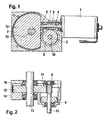
- the drive shown essentially consists of a drive motor 1, a worm gear stage 2 and a spur gear stage 3.
- the Motor shaft 4, which cooperates with a slide bearing 5 carries one Screw 6 with oblique toothing 7.
- the toothing 7 acts on Worm gear 8, which is opposite the motor shaft 4 with a Reduction ratio of 10: 1, 15: 1 or 24.5: 1 rotates, for example.
- a Reduction ratio is in a plastic version the worm wheel 8 possible.
- Around the speed again To reduce the factor by approximately 10 corresponds to a pinion 9 (FIG. 2) on the Worm gear shaft 10 with helical teeth 11 (FIG. 2) Spur gear 12.
- the spur gear shaft acts as an output shaft 13 of the electric motor drive.
- Figure 2 shows a section through the gear part of the drive, wherein a Housing 14 with cover 15 can be seen, whereby the compact structure of the between eighty times and two hundred and twenty times reducing Reduction gear becomes particularly clear.
Landscapes
- Engineering & Computer Science (AREA)
- General Engineering & Computer Science (AREA)
- Mechanical Engineering (AREA)
- Power Engineering (AREA)
- Gear Transmission (AREA)
- Power-Operated Mechanisms For Wings (AREA)
Abstract
Die Erfindung betrifft einen elektromotorischen Antrieb mit einem Getriebe, dessen Übersetzungsverhältnis im Bereich zwischen 80:1 und 220:1 liegt sowie eine Türautomatik, insbesondere für Schwingtüren, mit einem derartigen Antrieb. Ein besonders geräuscharmer und kompakter Antrieb, der bei der Verwendung in einer Türautomatik sowohl für rechtsanschlagende als auch für linksanschlagende Türen geeignet ist, ist dadurch gekennzeichnet, dass das Getriebe zwei Stufen aufweist, wobei die erste Stufe als Schneckengetriebestufe (2) und die zweite Stufe als Stirnradgetriebestufe (3) ausgebildet sind. <IMAGE>
Description
Die Erfindung betrifft einen elektromotorischen Antrieb gemäß dem
Oberbegriff des Anspruchs 1 sowie eine Türautomatik mit einem derartigen
Antrieb gemäß dem Oberbegriff des Anspruchs 3.
Elektromotorische Antriebe mit sehr hoher Drehzahlreduzierung zwischen
der Motorwelle und der Abtriebswelle werden im allgemeinen mittels
mehrstufiger Getriebe realisiert. Bekannt und gebräuchlich sind vor allem
Planeten-Kegelradgetriebekombinationen, Kegelrad-Stirnradgetriebekombinationen
oder mehrstufige Stirnradgetriebe. Diese
Reduziergetriebe sind mit mindestens drei Stufen ausgestattet. Vielstufige
Antriebe sind jedoch relativ teuer und voluminös. Außerdem sind störende
Geräusche auf Grund der diversen Verzahnungsteile kaum zu vermeiden.
Der Erfindung liegt die Aufgabe zu Grunde einen elektromotorischen
Antrieb der gattungsbildenden Art anzugeben, der sich durch kleinere
Bauform und leiseren Lauf auszeichnet.
Erfindungsgemäß wird die Aufgabe durch die kennzeichnenden Merkmale
des Anspruchs 1 gelöst. Durch die Zweistufigkeit ergibt sich eine
Verringerung der Baugröße, der Kosten und der Geräuschentwicklung. Da
kämmende Verzahnungen nur noch zwischen Motorwelle und
Schneckenrad sowie zwischen Schneckenradwelle und Stirnrad vorgesehen
sind, sind Geräuschpegel und Geräuschfrequenzen einfacher im Hinblick
auf leisen und frequenzmäßig angenehmen Lauf beeinflussbar als
beispielsweise bei dreistufigen Kegelrad-Stirnradgetrieben, bei denen drei
Verzahnungen für Unruhe sorgen. Kegelrad-Getriebestufen sind außerdem
nur für eine maximale Untersetzung von 6:1 geeignet. Um ein Gesamt-Übersetzungsverhältnis
von beispielsweise 120:1 zu erreichen, müsste
folglich noch um 20:1 untersetzt werden, so dass herkömmliche Antriebe
für ein derart hohes Gesamt-Übersetzungsverhältnis mindestens drei Stufen
benötigen. Eine Reduzierung auf zwei Stufen ist nur möglich, da die
Schneckengetriebestufe ein Übersetzungsverhältnis von bis zu 25:1
erreichen kann. Bei noch größeren Übersetzungsverhältnis wird der
Wirkungsgrad derart klein, dass das Getriebe selbsthemmend und damit
nicht mehr rücktreibbar wird.
Gemäß Anspruch 2 ist die Schneckengetriebestufe vorzugsweise mit einem
Kunststoff-Schneckenrad ausgestattet. Es hat sich gezeigt, dass der
Wirkungsgrad eines Kunststoff-Schneckenrades viel besser als der eines
herkömmlichen Metall-Schneckenrades ist. Letztlich ergibt sich dadurch die
Möglichkeit, Schneckenradgetriebestufen mit sehr hohem
Übersetzungsverhältnis herzustellen, ohne dadurch den Wirkungsgrad
unakzeptabel zu reduzieren. Auch die Selbsthemmungsneigung hält sich
bei dem beanspruchten Schneckenrad-Stirnradgetriebe in Grenzen, d.h.
dieses Getriebe lässt sich mit wenig Kraftaufwand in die Gegenrichtung
zurückstellen.
Diese Eigenschaften sind insbesondere bei einer in Anspruch 3
charakterisierten Türautomatik von Vorteil. Dabei dient der Antrieb zum
Öffnen der Tür, während das Federrückstellelement die Tür in eine
Ausgangsposition schwenkt. Die Federkraft kann bei Bedarf leicht
eingestellt werden. Darüber hinaus kann die Tür durch entsprechende
Federkraft aus Sicherheitsgründen, insbesondere bei Feuerschutztüren oder
bei Stromausfall, in eine Neutralposition geschwenkt werden.
Bei Türantrieben besteht das spezielle Problem, dass die Bauform
herkömmlicher Türautomatik bei linksanschlagenden und
rechtsanschlagenden Türen unterschiedlich sein muss.
Dieses Problem wird durch die kennzeichnenden Merkmale des Anspruchs
3 beseitigt. Der zweistufige Schnecken-Stirnradantrieb gestattet einen
symmetrischen Aufbau mittig zum Getriebegehäuse, wodurch der Antrieb
sowohl für rechtsanschlagenden als auch für linksanschlagende Türen
geeignet ist.
Gemäß Anspruch 4 wirkt das Federrückstellelement bevorzugt auf die
Schneckenradwelle der Schneckengetriebestufe. Bei bekannten
Türantrieben ist die Feder, welche die Tür in die Neutralposition oder die
Ausgangsposition schwenkt, an der Abtriebswelle angebracht. Dazu sind
erhebliche Federdrehmomente, verbunden mit großer und kostspieliger
Bauweise notwendig. Durch die Anbringung der Feder an der
Schneckenradwelle ergibt sich die Möglichkeit, ein geringeres
Federdrehmoment vorzusehen, sodass letztlich die Baugröße und Kosten
reduziert werden.
Insgesamt ergeben sich für die beanspruchte Türautomatik mit Schnecken-Stirnradgetriebe
gegenüber herkömmlichen Bauformen folgende Vorteile:
- Geräuschreduzierung,
- Verzahnungsteileredzierung,
- geringere Baugröße und
- einfache Änderung der Übersetzung durch Austausch der Schneckengetriebestufe.
Nachfragend wird die Erfindung anhand eines figürlich dargestellten
Ausführungsbeispiels näher erläutert.
Es zeigen:
- Figur 1
- einen ersten Querschnitt durch einen elektromotorischen Antrieb und
- Figur 2
- einen zweiten Querschnitt durch den Antrieb gemäß Figur 1.
Der dargestellte Antrieb besteht im wesentlichen aus einem Antriebsmotor
1, einer Schneckengetriebestufe 2 und einer Stirnradgetriebestufe 3. Die
Motorwelle 4, die mit einem Gleitlager 5 zusammenwirkt, trägt eine
Schnecke 6 mit schräger Verzahnung 7. Die Verzahnung 7 wirkt auf ein
Schneckenrad 8, das sich gegenüber der Motorwelle 4 mit einem
Untersetzungsverhältnis von beispielsweise 10:1, 15:1 oder 24,5:1 dreht.
Ein derart großes Untersetzungsverhältnis ist bei einer Kunststoffausführung
des Schneckenrades 8 möglich. Um die Drehzahl noch mal um einen
Faktor von circa 10 zu senken, korrespondiert ein Ritzel 9 (Figur 2) auf der
Schneckenradwelle 10 mit einer Schrägverzahnung 11 (Figur 2) eines
Stirnrades 12. Die Stirnradwelle fungiert als Abtriebswelle 13 des
elektromotorischen Antriebes.
Figur 2 zeigt einen Schnitt durch den Getriebeteil des Antriebes, wobei ein
Gehäuse 14 mit Deckel 15 ersichtlich ist, womit der kompakte Aufbau des
zwischen achtzigfach und zweihundertfzwanzigfach untersetzenden
Reduziergetriebes besonders deutlich wird.
Claims (4)
- Elektromotorischer Antrieb mit einem Getriebe, dessen Übersetzungsverhältnis mindestens 80:1 beträgt,
dadurch gekennzeichnet, dass das Getriebe zwei Stufen aufweist, wobei die erste Stufe als Schneckengetriebestufe (2) und die zweite Stufe als Stirnradgetriebestufe (3) ausgebildet sind. - Antrieb nach Anspruch 1, dadurch gekennzeichnet, dass die Schneckengetriebestufe (2) ein Kunststoff-Schneckenrad (8) aufweist.
- Türautomatik, insbesondere für Schwingtüren, mit einem Antrieb nach einem der vorangehenden Ansprüche und einem Federrückstellelement, dadurch gekennzeichnet, dass der Antrieb eine für rechtsanschlagende und linksanschlagende Türen geeignete symmetrische Bauform aufweist.
- Türautomatik nach Anspruch 3, dadurch gekennzeichnet, dass das Federrückstellelement die Schneckenradwelle (10) der Schneckengetriebestufe (2) beaufschlagt.
Priority Applications (1)
| Application Number | Priority Date | Filing Date | Title |
|---|---|---|---|
| DE20220266U DE20220266U1 (de) | 2001-02-26 | 2002-02-11 | Elektromotorischer Antrieb und Türautomatik |
Applications Claiming Priority (2)
| Application Number | Priority Date | Filing Date | Title |
|---|---|---|---|
| DE10109278A DE10109278A1 (de) | 2001-02-26 | 2001-02-26 | Elektromotorischer Antrieb und Türautomatik |
| DE10109278 | 2001-02-26 |
Publications (1)
| Publication Number | Publication Date |
|---|---|
| EP1235330A1 true EP1235330A1 (de) | 2002-08-28 |
Family
ID=7675573
Family Applications (1)
| Application Number | Title | Priority Date | Filing Date |
|---|---|---|---|
| EP02360059A Withdrawn EP1235330A1 (de) | 2001-02-26 | 2002-02-11 | Elektromotorischer Antrieb und Türautomatik mit Schneckenradgetriebe |
Country Status (3)
| Country | Link |
|---|---|
| US (1) | US20020117917A1 (de) |
| EP (1) | EP1235330A1 (de) |
| DE (1) | DE10109278A1 (de) |
Cited By (6)
| Publication number | Priority date | Publication date | Assignee | Title |
|---|---|---|---|---|
| EP1359277A1 (de) * | 2002-04-17 | 2003-11-05 | Delphi Technologies, Inc. | Motorbetriebene Antriebsvorrichtung für ein Schliesselement eines Fahrzeuges |
| US7578094B2 (en) | 2003-03-05 | 2009-08-25 | Strattec Power Access Llc | Drive unit for power operated vehicle closure |
| EP2189605A1 (de) * | 2008-11-25 | 2010-05-26 | Lorenzo Cavalieri Ducati | Türöffnungs- oder Toröffnungsvorrichtung mit vereinfachter mechanischer Kraftübertragung |
| CZ304950B6 (cs) * | 2013-02-15 | 2015-02-04 | Vysoká Škola Báňská-Technická Univerzita Ostrava | Zařízení pro otevírání pátých dveří nebo zadního víka automobilu |
| EP3034755A1 (de) * | 2014-12-17 | 2016-06-22 | DORMA Deutschland GmbH | Faltflügeltüranlage |
| EP3912258A1 (de) * | 2019-01-18 | 2021-11-24 | GEZE GmbH | Antrieb für eine karusselldrehtür |
Families Citing this family (5)
| Publication number | Priority date | Publication date | Assignee | Title |
|---|---|---|---|---|
| KR101428302B1 (ko) * | 2012-12-21 | 2014-08-07 | 현대자동차주식회사 | 액티브 에어플랩 장치용 액추에이터 |
| CN103527028B (zh) * | 2013-10-18 | 2016-04-13 | 无锡麻德克斯精机有限公司 | 洗碗机的自动开门组件 |
| DE102017207931A1 (de) * | 2017-05-10 | 2018-11-15 | Mahle International Gmbh | Baukastensystem zum Herstellen einer Stelleinrichtung |
| DE102017207929B4 (de) * | 2017-05-10 | 2024-08-22 | Mahle Lnternational Gmbh | Stelleinrichtung und zugehöriges Herstellungsverfahren |
| US10793183B2 (en) * | 2017-12-22 | 2020-10-06 | Trw Automotive U.S. Llc | Torque overlay steering apparatus |
Citations (10)
| Publication number | Priority date | Publication date | Assignee | Title |
|---|---|---|---|---|
| DE2446839A1 (de) * | 1974-10-01 | 1976-04-15 | Bosch Gmbh Robert | Vorrichtung, insbesondere zum antrieb einer wischerwelle von wischvorrichtungen |
| DE3209608A1 (de) * | 1982-03-17 | 1983-09-29 | Magnetic-Elektromotoren GmbH, 7867 Maulburg | Antrieb fuer tueren u. dgl. |
| EP0233729A2 (de) * | 1986-02-10 | 1987-08-26 | Polyplastics Co. Ltd. | Drehteile |
| US5036620A (en) * | 1990-09-17 | 1991-08-06 | Bc Research & Development, Inc. | Safety enhanced pivoting door operator |
| EP0622564A1 (de) * | 1993-04-29 | 1994-11-02 | Eaton Corporation | Geräuscharmer Servobetätiger |
| JPH0874969A (ja) * | 1994-09-01 | 1996-03-19 | Koyo Seiko Co Ltd | ウォームギヤ装置 |
| GB2338028A (en) * | 1998-05-28 | 1999-12-08 | Nt Dor O Matic Inc | Powered door operator |
| US6006475A (en) * | 1998-03-04 | 1999-12-28 | Nabco Entrances Inc. | Spring loaded swinging door system |
| US6029763A (en) * | 1997-08-27 | 2000-02-29 | Reliance Electric Industrial Company | Worm gear assembly for a medical mobility apparatus permitting manual reverse mobility |
| JP2000356070A (ja) * | 1999-06-16 | 2000-12-26 | Asmo Co Ltd | ドア開閉装置 |
Family Cites Families (10)
| Publication number | Priority date | Publication date | Assignee | Title |
|---|---|---|---|---|
| DE2818439A1 (de) * | 1978-04-27 | 1979-11-08 | Magnetic Elektromotoren Gmbh | Antrieb fuer tueren u.dgl. |
| DE2905869A1 (de) * | 1979-02-16 | 1980-08-28 | Rau Swf Autozubehoer | Elektrisches antriebsaggregat |
| US4226136A (en) * | 1979-05-24 | 1980-10-07 | Illinois Tool Works Inc. | Gear drive assembly |
| JPH082353Y2 (ja) * | 1988-12-15 | 1996-01-24 | 日産自動車株式会社 | アクチュエータ |
| DE4138625B4 (de) * | 1991-11-25 | 2010-07-22 | Robert Bosch Gmbh | Elektromotorischer Stellantrieb |
| JPH10159439A (ja) * | 1996-12-03 | 1998-06-16 | Asmo Co Ltd | チルト窓用開閉装置 |
| US6465915B1 (en) * | 1999-05-21 | 2002-10-15 | Molon Motor & Coil Corporation | Miniaturized motor |
| US6054785A (en) * | 1999-05-21 | 2000-04-25 | Molon Motor & Coil Corporation | Compact miniature motor |
| JP2001041159A (ja) * | 1999-08-02 | 2001-02-13 | Nidec Copal Corp | 小型エアポンプ |
| US6617726B1 (en) * | 2002-05-02 | 2003-09-09 | Molon Motor & Coil Corporation | Motor gear box |
-
2001
- 2001-02-26 DE DE10109278A patent/DE10109278A1/de not_active Withdrawn
-
2002
- 2002-02-11 EP EP02360059A patent/EP1235330A1/de not_active Withdrawn
- 2002-02-20 US US10/078,004 patent/US20020117917A1/en not_active Abandoned
Patent Citations (10)
| Publication number | Priority date | Publication date | Assignee | Title |
|---|---|---|---|---|
| DE2446839A1 (de) * | 1974-10-01 | 1976-04-15 | Bosch Gmbh Robert | Vorrichtung, insbesondere zum antrieb einer wischerwelle von wischvorrichtungen |
| DE3209608A1 (de) * | 1982-03-17 | 1983-09-29 | Magnetic-Elektromotoren GmbH, 7867 Maulburg | Antrieb fuer tueren u. dgl. |
| EP0233729A2 (de) * | 1986-02-10 | 1987-08-26 | Polyplastics Co. Ltd. | Drehteile |
| US5036620A (en) * | 1990-09-17 | 1991-08-06 | Bc Research & Development, Inc. | Safety enhanced pivoting door operator |
| EP0622564A1 (de) * | 1993-04-29 | 1994-11-02 | Eaton Corporation | Geräuscharmer Servobetätiger |
| JPH0874969A (ja) * | 1994-09-01 | 1996-03-19 | Koyo Seiko Co Ltd | ウォームギヤ装置 |
| US6029763A (en) * | 1997-08-27 | 2000-02-29 | Reliance Electric Industrial Company | Worm gear assembly for a medical mobility apparatus permitting manual reverse mobility |
| US6006475A (en) * | 1998-03-04 | 1999-12-28 | Nabco Entrances Inc. | Spring loaded swinging door system |
| GB2338028A (en) * | 1998-05-28 | 1999-12-08 | Nt Dor O Matic Inc | Powered door operator |
| JP2000356070A (ja) * | 1999-06-16 | 2000-12-26 | Asmo Co Ltd | ドア開閉装置 |
Non-Patent Citations (2)
| Title |
|---|
| PATENT ABSTRACTS OF JAPAN vol. 1996, no. 07 31 July 1996 (1996-07-31) * |
| PATENT ABSTRACTS OF JAPAN vol. 2000, no. 15 6 April 2001 (2001-04-06) * |
Cited By (7)
| Publication number | Priority date | Publication date | Assignee | Title |
|---|---|---|---|---|
| EP1359277A1 (de) * | 2002-04-17 | 2003-11-05 | Delphi Technologies, Inc. | Motorbetriebene Antriebsvorrichtung für ein Schliesselement eines Fahrzeuges |
| US7578094B2 (en) | 2003-03-05 | 2009-08-25 | Strattec Power Access Llc | Drive unit for power operated vehicle closure |
| EP2189605A1 (de) * | 2008-11-25 | 2010-05-26 | Lorenzo Cavalieri Ducati | Türöffnungs- oder Toröffnungsvorrichtung mit vereinfachter mechanischer Kraftübertragung |
| ITMI20082099A1 (it) * | 2008-11-25 | 2010-05-26 | Ducati Lorenzo Cavalieri | Dispositivo apriporta o apricancello a trasmissione meccanica semplificata |
| CZ304950B6 (cs) * | 2013-02-15 | 2015-02-04 | Vysoká Škola Báňská-Technická Univerzita Ostrava | Zařízení pro otevírání pátých dveří nebo zadního víka automobilu |
| EP3034755A1 (de) * | 2014-12-17 | 2016-06-22 | DORMA Deutschland GmbH | Faltflügeltüranlage |
| EP3912258A1 (de) * | 2019-01-18 | 2021-11-24 | GEZE GmbH | Antrieb für eine karusselldrehtür |
Also Published As
| Publication number | Publication date |
|---|---|
| DE10109278A1 (de) | 2002-09-05 |
| US20020117917A1 (en) | 2002-08-29 |
Similar Documents
| Publication | Publication Date | Title |
|---|---|---|
| EP1266153B1 (de) | Getriebebaukasten | |
| EP2933415B1 (de) | Türantrieb | |
| DE19637361A1 (de) | Adapter und Adaptersystem zum Verbinden von Motoren mit Getrieben | |
| EP1298274B1 (de) | Flügeltürantrieb mit Federschliessung | |
| EP1235330A1 (de) | Elektromotorischer Antrieb und Türautomatik mit Schneckenradgetriebe | |
| DE102016118877B4 (de) | Mechanische Getriebeanordnung | |
| DE19931818A1 (de) | Mehrstufiges Stirnradgetriebe | |
| WO2023036364A1 (de) | Kraftfahrzeug-schloss insbesondere kraftfahrzeug-türschloss | |
| DE4102932A1 (de) | Getriebemotor | |
| EP3907420A1 (de) | Planspiralgetriebe sowie torantriebskomponente und torantrieb mit einem solchen getriebe | |
| DE20107324U1 (de) | Verstellantrieb | |
| WO2020148174A1 (de) | Antrieb für eine karusselldrehtür | |
| EP1418070A1 (de) | Vorrichtung zum Verstellen einer Klappe für Heizungs-, Lüftungs-und Klimaanlagen | |
| EP4613961A1 (de) | Elektromotorischer klappenantrieb für gebäudeöffnungen mit notantriebsfunktion | |
| EP1134453A2 (de) | Antrieb für ein verstellbares Fahrzeugteil | |
| WO1999011949A1 (de) | Getriebe mit grossem untersetzungsverhältnis | |
| EP0686788A1 (de) | Getriebe für einen Getriebemotor | |
| DE20220266U1 (de) | Elektromotorischer Antrieb und Türautomatik | |
| DE19932262C1 (de) | Einklappbarer Rückspiegel für Kaftfahrzeuge | |
| EP0983418A1 (de) | Antriebsvorrichtung für ein seitenausstellfenster eines fahrzeuges | |
| EP0014240A1 (de) | Nothandkurbel für motorische Antriebe von Rolltoren od.dgl. | |
| DE102023208572B3 (de) | Türantrieb und Türsystem | |
| DE102015202852B3 (de) | Türantrieb | |
| EP1045169A2 (de) | Getriebereihe | |
| WO2005061832A2 (de) | Fensterhebersystem mit wahlweise einsetzbarer manueller oder motorischer antriebseinrichtung |
Legal Events
| Date | Code | Title | Description |
|---|---|---|---|
| PUAI | Public reference made under article 153(3) epc to a published international application that has entered the european phase |
Free format text: ORIGINAL CODE: 0009012 |
|
| AK | Designated contracting states |
Kind code of ref document: A1 Designated state(s): AT BE CH CY DE DK ES FI FR GB GR IE IT LI LU MC NL PT SE TR |
|
| AX | Request for extension of the european patent |
Free format text: AL;LT;LV;MK;RO;SI |
|
| AKX | Designation fees paid | ||
| REG | Reference to a national code |
Ref country code: DE Ref legal event code: 8566 |
|
| STAA | Information on the status of an ep patent application or granted ep patent |
Free format text: STATUS: THE APPLICATION IS DEEMED TO BE WITHDRAWN |
|
| 18D | Application deemed to be withdrawn |
Effective date: 20030301 |