EP1234906B1 - Bulky structured melblown nonwoven web - Google Patents
Bulky structured melblown nonwoven web Download PDFInfo
- Publication number
- EP1234906B1 EP1234906B1 EP02001390A EP02001390A EP1234906B1 EP 1234906 B1 EP1234906 B1 EP 1234906B1 EP 02001390 A EP02001390 A EP 02001390A EP 02001390 A EP02001390 A EP 02001390A EP 1234906 B1 EP1234906 B1 EP 1234906B1
- Authority
- EP
- European Patent Office
- Prior art keywords
- fleece
- structured
- melt
- voluminous
- blown
- Prior art date
- Legal status (The legal status is an assumption and is not a legal conclusion. Google has not performed a legal analysis and makes no representation as to the accuracy of the status listed.)
- Expired - Lifetime
Links
- 230000001788 irregular Effects 0.000 claims abstract description 3
- 102000002151 Microfilament Proteins Human genes 0.000 claims abstract 3
- 108010040897 Microfilament Proteins Proteins 0.000 claims abstract 3
- 210000003632 microfilament Anatomy 0.000 claims abstract 3
- 238000004519 manufacturing process Methods 0.000 claims description 13
- 230000035699 permeability Effects 0.000 claims description 9
- 239000003658 microfiber Substances 0.000 claims description 6
- 229920001410 Microfiber Polymers 0.000 claims description 5
- 229920001169 thermoplastic Polymers 0.000 claims 4
- 239000000203 mixture Substances 0.000 claims 2
- 239000004416 thermosoftening plastic Substances 0.000 claims 2
- 229920001519 homopolymer Polymers 0.000 claims 1
- 230000002209 hydrophobic effect Effects 0.000 claims 1
- 239000000428 dust Substances 0.000 description 16
- 239000004745 nonwoven fabric Substances 0.000 description 16
- 238000003860 storage Methods 0.000 description 13
- 239000000835 fiber Substances 0.000 description 11
- 238000009826 distribution Methods 0.000 description 10
- 239000004750 melt-blown nonwoven Substances 0.000 description 10
- 238000004140 cleaning Methods 0.000 description 9
- 239000004744 fabric Substances 0.000 description 8
- 230000000694 effects Effects 0.000 description 7
- 239000012530 fluid Substances 0.000 description 7
- 239000007788 liquid Substances 0.000 description 6
- 238000000034 method Methods 0.000 description 6
- 210000001124 body fluid Anatomy 0.000 description 5
- 239000010839 body fluid Substances 0.000 description 5
- OKTJSMMVPCPJKN-UHFFFAOYSA-N Carbon Chemical compound [C] OKTJSMMVPCPJKN-UHFFFAOYSA-N 0.000 description 4
- 239000000463 material Substances 0.000 description 4
- 230000008569 process Effects 0.000 description 4
- 238000010521 absorption reaction Methods 0.000 description 3
- 239000011521 glass Substances 0.000 description 3
- 239000002245 particle Substances 0.000 description 3
- 230000009467 reduction Effects 0.000 description 3
- 239000002250 absorbent Substances 0.000 description 2
- 230000002745 absorbent Effects 0.000 description 2
- 230000007423 decrease Effects 0.000 description 2
- 238000001914 filtration Methods 0.000 description 2
- 238000012432 intermediate storage Methods 0.000 description 2
- 239000007787 solid Substances 0.000 description 2
- 239000007858 starting material Substances 0.000 description 2
- 230000009471 action Effects 0.000 description 1
- 230000015572 biosynthetic process Effects 0.000 description 1
- 229920002678 cellulose Polymers 0.000 description 1
- 239000001913 cellulose Substances 0.000 description 1
- 239000003610 charcoal Substances 0.000 description 1
- 239000007795 chemical reaction product Substances 0.000 description 1
- 230000006835 compression Effects 0.000 description 1
- 238000007906 compression Methods 0.000 description 1
- 238000010276 construction Methods 0.000 description 1
- 239000000498 cooling water Substances 0.000 description 1
- 238000005516 engineering process Methods 0.000 description 1
- 238000011156 evaluation Methods 0.000 description 1
- 239000002657 fibrous material Substances 0.000 description 1
- 239000011888 foil Substances 0.000 description 1
- 239000007789 gas Substances 0.000 description 1
- 239000008187 granular material Substances 0.000 description 1
- 230000006872 improvement Effects 0.000 description 1
- 239000004615 ingredient Substances 0.000 description 1
- 239000000047 product Substances 0.000 description 1
- 230000001105 regulatory effect Effects 0.000 description 1
- 238000000926 separation method Methods 0.000 description 1
- 239000000126 substance Substances 0.000 description 1
- 230000004584 weight gain Effects 0.000 description 1
- 235000019786 weight gain Nutrition 0.000 description 1
Images


Classifications
-
- D—TEXTILES; PAPER
- D04—BRAIDING; LACE-MAKING; KNITTING; TRIMMINGS; NON-WOVEN FABRICS
- D04H—MAKING TEXTILE FABRICS, e.g. FROM FIBRES OR FILAMENTARY MATERIAL; FABRICS MADE BY SUCH PROCESSES OR APPARATUS, e.g. FELTS, NON-WOVEN FABRICS; COTTON-WOOL; WADDING ; NON-WOVEN FABRICS FROM STAPLE FIBRES, FILAMENTS OR YARNS, BONDED WITH AT LEAST ONE WEB-LIKE MATERIAL DURING THEIR CONSOLIDATION
- D04H3/00—Non-woven fabrics formed wholly or mainly of yarns or like filamentary material of substantial length
- D04H3/005—Synthetic yarns or filaments
-
- B—PERFORMING OPERATIONS; TRANSPORTING
- B01—PHYSICAL OR CHEMICAL PROCESSES OR APPARATUS IN GENERAL
- B01D—SEPARATION
- B01D39/00—Filtering material for liquid or gaseous fluids
- B01D39/14—Other self-supporting filtering material ; Other filtering material
- B01D39/16—Other self-supporting filtering material ; Other filtering material of organic material, e.g. synthetic fibres
- B01D39/1607—Other self-supporting filtering material ; Other filtering material of organic material, e.g. synthetic fibres the material being fibrous
- B01D39/1623—Other self-supporting filtering material ; Other filtering material of organic material, e.g. synthetic fibres the material being fibrous of synthetic origin
-
- D—TEXTILES; PAPER
- D04—BRAIDING; LACE-MAKING; KNITTING; TRIMMINGS; NON-WOVEN FABRICS
- D04H—MAKING TEXTILE FABRICS, e.g. FROM FIBRES OR FILAMENTARY MATERIAL; FABRICS MADE BY SUCH PROCESSES OR APPARATUS, e.g. FELTS, NON-WOVEN FABRICS; COTTON-WOOL; WADDING ; NON-WOVEN FABRICS FROM STAPLE FIBRES, FILAMENTS OR YARNS, BONDED WITH AT LEAST ONE WEB-LIKE MATERIAL DURING THEIR CONSOLIDATION
- D04H1/00—Non-woven fabrics formed wholly or mainly of staple fibres or like relatively short fibres
- D04H1/40—Non-woven fabrics formed wholly or mainly of staple fibres or like relatively short fibres from fleeces or layers composed of fibres without existing or potential cohesive properties
- D04H1/54—Non-woven fabrics formed wholly or mainly of staple fibres or like relatively short fibres from fleeces or layers composed of fibres without existing or potential cohesive properties by welding together the fibres, e.g. by partially melting or dissolving
- D04H1/56—Non-woven fabrics formed wholly or mainly of staple fibres or like relatively short fibres from fleeces or layers composed of fibres without existing or potential cohesive properties by welding together the fibres, e.g. by partially melting or dissolving in association with fibre formation, e.g. immediately following extrusion of staple fibres
-
- D—TEXTILES; PAPER
- D04—BRAIDING; LACE-MAKING; KNITTING; TRIMMINGS; NON-WOVEN FABRICS
- D04H—MAKING TEXTILE FABRICS, e.g. FROM FIBRES OR FILAMENTARY MATERIAL; FABRICS MADE BY SUCH PROCESSES OR APPARATUS, e.g. FELTS, NON-WOVEN FABRICS; COTTON-WOOL; WADDING ; NON-WOVEN FABRICS FROM STAPLE FIBRES, FILAMENTS OR YARNS, BONDED WITH AT LEAST ONE WEB-LIKE MATERIAL DURING THEIR CONSOLIDATION
- D04H3/00—Non-woven fabrics formed wholly or mainly of yarns or like filamentary material of substantial length
- D04H3/02—Non-woven fabrics formed wholly or mainly of yarns or like filamentary material of substantial length characterised by the method of forming fleeces or layers, e.g. reorientation of yarns or filaments
-
- D—TEXTILES; PAPER
- D04—BRAIDING; LACE-MAKING; KNITTING; TRIMMINGS; NON-WOVEN FABRICS
- D04H—MAKING TEXTILE FABRICS, e.g. FROM FIBRES OR FILAMENTARY MATERIAL; FABRICS MADE BY SUCH PROCESSES OR APPARATUS, e.g. FELTS, NON-WOVEN FABRICS; COTTON-WOOL; WADDING ; NON-WOVEN FABRICS FROM STAPLE FIBRES, FILAMENTS OR YARNS, BONDED WITH AT LEAST ONE WEB-LIKE MATERIAL DURING THEIR CONSOLIDATION
- D04H3/00—Non-woven fabrics formed wholly or mainly of yarns or like filamentary material of substantial length
- D04H3/08—Non-woven fabrics formed wholly or mainly of yarns or like filamentary material of substantial length characterised by the method of strengthening or consolidating
- D04H3/16—Non-woven fabrics formed wholly or mainly of yarns or like filamentary material of substantial length characterised by the method of strengthening or consolidating with bonds between thermoplastic filaments produced in association with filament formation, e.g. immediately following extrusion
-
- D—TEXTILES; PAPER
- D04—BRAIDING; LACE-MAKING; KNITTING; TRIMMINGS; NON-WOVEN FABRICS
- D04H—MAKING TEXTILE FABRICS, e.g. FROM FIBRES OR FILAMENTARY MATERIAL; FABRICS MADE BY SUCH PROCESSES OR APPARATUS, e.g. FELTS, NON-WOVEN FABRICS; COTTON-WOOL; WADDING ; NON-WOVEN FABRICS FROM STAPLE FIBRES, FILAMENTS OR YARNS, BONDED WITH AT LEAST ONE WEB-LIKE MATERIAL DURING THEIR CONSOLIDATION
- D04H5/00—Non woven fabrics formed of mixtures of relatively short fibres and yarns or like filamentary material of substantial length
- D04H5/06—Non woven fabrics formed of mixtures of relatively short fibres and yarns or like filamentary material of substantial length strengthened or consolidated by welding-together thermoplastic fibres, filaments, or yarns
-
- D—TEXTILES; PAPER
- D04—BRAIDING; LACE-MAKING; KNITTING; TRIMMINGS; NON-WOVEN FABRICS
- D04H—MAKING TEXTILE FABRICS, e.g. FROM FIBRES OR FILAMENTARY MATERIAL; FABRICS MADE BY SUCH PROCESSES OR APPARATUS, e.g. FELTS, NON-WOVEN FABRICS; COTTON-WOOL; WADDING ; NON-WOVEN FABRICS FROM STAPLE FIBRES, FILAMENTS OR YARNS, BONDED WITH AT LEAST ONE WEB-LIKE MATERIAL DURING THEIR CONSOLIDATION
- D04H5/00—Non woven fabrics formed of mixtures of relatively short fibres and yarns or like filamentary material of substantial length
- D04H5/08—Non woven fabrics formed of mixtures of relatively short fibres and yarns or like filamentary material of substantial length characterised by the method of forming fleeces or layers, e.g. reorientation of fibres or yarns
Definitions
- meltblown nonwovens have a good filtration action against liquid or gaseous fluids.
- the disadvantage here is the fact that the storage effect for the deposited ingredients of the fluids is usually low, which leads to clogging of the filter media while drastically reducing the service life.
- the DE application 101 03 627.2 discloses a zone-wise thermally compressed meltblown nonwoven which is used in the area of uptake and distribution nonwoven fabrics Application can be found. Again, a structure can be seen, which consists of zones of low and high thickness.
- the main drawback here too lies in the compression of the starting materials used.
- the end product has a very good and controlled distribution effect, the absorption capacity is, however, limited due to the mentioned precompression, and therefore in need of improvement.
- the US 5,858,515 shows a fleece, which is embossed by means of a calender, so that point-like, unconsolidated areas arise in the fleece.
- the object of the invention was therefore to avoid the disadvantages of the prior art and to provide a meltblown web which has a surface structure at low basis weight and high thickness and cavities for the storage of particles provides, so that a high fluid passage while maintaining good storage capacity is ensured for the fluids themselves, or for contained in the fluids solids or liquids.
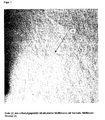
- the nonwoven fabric according to the invention as in the FIGS. 1 to 3 shown, characterized by a two-sidedness, wherein the one side (2) has a smooth surface and the other side (1) has an irregular coarse structure (3). Depending on the manufacturing process, this can vary from relief-like over leathery scarred to tree-bark-like appearance.
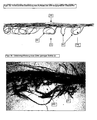
- FIG. 3 shows the arrangement of the higher density zones (a) to the lower density zones (b).
- the zones of low density (b) are formed by loop-shaped or hook-shaped multi-microfilament strands (4) and contain cavities (15).
- microfiber stream (8) is formed, which in addition to the microfibers also contains microfiber filaments and multi-microfilament strands (4).
- the center axis of the meltblown nozzle (6) to the central axis of the collector drum (7) is negative, that is, contrary to the direction of production, shifted by the length (11).
- the opening (14) of the vacuum device is positioned in the collector drum (7) in the 1 o'clock position, so that there is no vacuum in the impact zone (9).
- the distance of the collector drum (7) to the meltblown nozzle (6) is to be dimensioned so that the multi-microfilament strands still have a certain stickiness and can connect to each other.
- the surface structure (5) as in FIG. 1 shown.
- the primary air stream necessary for forming the meltblown fibers at the outlet of the meltblown nozzle (6) is set so that the delivery rate of primary air is 40% greater than the direction of production the flow rate in the production direction.
- Table 1 Exemplary machine setting for the production of the nonwoven fabric according to the invention State of the art According to the invention Granules: PP Borealis FL 508 PP Borealis FL 508 Cooling water pressure: 40 bar 30 bar Distance between meltblown nozzle (6) and collector drum (7) 20 cm 63 cm Primary air flow 33 m 3 / h on both sides 38 m 3 / h in the opposite direction of production 25 m 3 / h in the production direction Extruder temperature: 250 ° C 250 ° C Nozzle tip: 280 ° C 280 ° C Power at the nozzle tip 40 kg / h * m 40 kg / h * m Length (11) (offset MB nozzle (6) to collector drum (7) 0 cm 18 cm Speed of the collector drum 13.6 m / min 13.4 m / min Air passage 200Pa: 430 l / m 2 * s 2400 l / m 2 * s grammage 49 g / m 2 51 g /
- the resulting stream of meltblown fibers (8) hits through the described settings, the impact zone (9) of the collector drum (7) with its short leg (12) in the 11 o'clock position and with its long leg (13) tangent to the Surface of the collector drum (7).
- the low density zones formed (b) have heights of 0.3 mm to 1.8 mm.
- the formation of the multi-microfilament strands is promoted in the production, for example by turbulence due to the different primary air volume flows and by increasing the length (11), it is easier to produce large cavities (15) in the zones of low density (b) the restoring force of the individually multi-microfilament strands (4) increases and the layering towards the loop or hook position is enhanced.
- the inventive structure can only be seen on the collector drum (7) facing side (1) of the meltblown nonwoven fabric according to the invention.
- the collector drum (7) facing away from side (2) has a normal meltblown structure (5), which gives the nonwoven the required mechanical stability.
- the nonwoven fabric according to the invention thus produced, for example, can be used in a large number of fields of application. Below are just a few of them called and deepened.
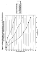
- Table 2 Dependence of the air permeability (LD) in l / m2 * s at 200Pa on the dust load in g Load (g) Paper + carded fleece Paper + fine fiber MB Paper + erf.gem. MB Stable MB + erf.gem.
- nonwoven fabric according to the invention can be used here in other areas, such as diapers or sanitary napkins, especially as a receiving and distribution nonwoven fabric.
- the task here is the rapid absorption of liquids, the intermediate storage and the forwarding of these to the absorbent body.
- the distribution happens concentrically around the task point, is insufficient in the recording / distributing position and mainly takes place in the suction / storage layer that is actually to be relieved.
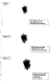
- FIGS. 8 to 11 show a comparatively carried out test with a structured nonwoven fabric according to the invention used as a receiving / distributing layer.
- meltblown nonwoven fabric structured according to the invention is also superior to the prior art in other areas, for example when used as a cleaning cloth, especially for cleaning smooth surfaces such as glass or plastic.
- the side (2) of the nonwoven fabric according to the invention is suitable.
- the combination of the existing fine meltblown fibers and the coarse multi-microfilament strands results in an improved cleaning effect compared to the prior art.
- the nonwoven fabric can then store the loosened dirt particles in the cavities and mask them so that they no longer "smear" during the further wiping process.
- meltblown nonwoven fabric structured in accordance with the invention exhibited a dirt storage capacity nearly three times higher than a commercially available dust wiping cloth manufactured according to the prior art.
- the voluminous meltblown nonwoven fabric structured according to the invention can be used in a large number of fields of application. Especially in applications requiring the uptake and storage of solid or liquid substances, the claimed nonwoven fabric is superior to the prior art.
Landscapes
- Engineering & Computer Science (AREA)
- Textile Engineering (AREA)
- Chemical & Material Sciences (AREA)
- Chemical Kinetics & Catalysis (AREA)
- Nonwoven Fabrics (AREA)
- Spinning Methods And Devices For Manufacturing Artificial Fibers (AREA)
- Orthopedics, Nursing, And Contraception (AREA)
Abstract
Description
Bekannte Meltblown-Vliesstoffe haben eine gute Filtrationswirkung gegenüber flüssigen oder gasförmigen Fluiden. Nachteilig wirkt sich dabei die Tatsache aus, dass die Speicherwirkung für die abgeschiedenen Inhaltsstoffe der Fluide meist nur gering ist, was zum Verstopfen der Filtermedien unter gleichzeitig drastischer Verringerung der Standzeit führt.Known meltblown nonwovens have a good filtration action against liquid or gaseous fluids. The disadvantage here is the fact that the storage effect for the deposited ingredients of the fluids is usually low, which leads to clogging of the filter media while drastically reducing the service life.
Um dieses Problem zu lösen, wurde eine Vielzahl von Anstrengungen unternommen, von welchen nachstehend einige stellvertretend genannt sind.To solve this problem, a variety of efforts have been made, some of which are mentioned below as representative.
So wird beispielsweise in der
Die
Wie in der vorhergehend genannten Schrift bereits beschrieben, liegt auch hier der Hauptnachteil in der Komprimierung der verwendeten Ausgangsmaterialien. Das Endprodukt verfügt zwar über eine sehr gute und kontrollierte Verteilwirkung, die Aufnahmefähigkeit ist jedoch, aufgrund der erwähnten Vorkomprimierung, beschränkt und daher verbesserungsbedürftig.As already described in the above-mentioned document, the main drawback here too lies in the compression of the starting materials used. Although the end product has a very good and controlled distribution effect, the absorption capacity is, however, limited due to the mentioned precompression, and therefore in need of improvement.
Die
Die Aufgabe der Erfindung war es daher, die Nachteile des Standes der Technik zu vermeiden und ein Meltblown-Vlies bereitzustellen, welches bei niedrigem Flächengewicht und hoher Dicke eine Oberflächenstruktur aufweist und Kavitäten für die Speicherung von Partikeln bereitstellt, sodaß ein hoher Fluiddurchgang bei gleichzeitig gutem Speichervermögen für die Fluide selbst, beziehungsweise für in den Fluiden enthaltene Feststoffe bzw. Flüssigkeiten gewährleistet ist.The object of the invention was therefore to avoid the disadvantages of the prior art and to provide a meltblown web which has a surface structure at low basis weight and high thickness and cavities for the storage of particles provides, so that a high fluid passage while maintaining good storage capacity is ensured for the fluids themselves, or for contained in the fluids solids or liquids.
Die Aufgabe ist gemäß den Merkmalen des Anspruches 1 gelöst. Vorteilhafte Ausgestaltungen sind in den Unteransprüchen 2-14 genannt.The object is solved according to the features of
Der erfindungsgemäße Vliesstoff, wie in den
Wie in
Die
Ein möglicher Verfahrensweg für die Herstellung einer derartigen Struktur wird in der
Ausgehend von einem bekannten Meltblown-Prozess, wie etwa erläutert in der
Dabei ist die Mittelachse der Meltblown-Düse (6) zur Mittelachse der Kollektortrommel (7) negativ, das heisst entgegen der Fertigungsrichtung, um die Länge (11) verschoben.Here, the center axis of the meltblown nozzle (6) to the central axis of the collector drum (7) is negative, that is, contrary to the direction of production, shifted by the length (11).
Desweiteren ist zur Herstellung des erfindungsgemäßen Vliesstoffes die Öffnung (14) der Vakuumeinrichtung in der Kollektortrommel (7) in 1-Uhr-Stellung positioniert, sodaß in der Aufprallzone (9) kein Vakuum herrscht.Furthermore, for the production of the nonwoven fabric according to the invention, the opening (14) of the vacuum device is positioned in the collector drum (7) in the 1 o'clock position, so that there is no vacuum in the impact zone (9).
Der Abstand der Kollektortrommel (7) zur Meltblown-Düse (6) ist dabei so zu bemessen, dass die Multi-Mikrofilamentstränge noch eine gewisse Klebrigkeit aufweisen und sich so untereinander verbinden können. Dadurch bildet sich auf der der Kollektortrommel (7) abgewandten Seite (2) die Oberflächenstruktur (5), wie in
Wie sich aus den in Tabelle 1 beispielsweise genannten Maschineneinstellungen entnehmen lässt, wird der zur Ausbildung der Meltblown-Fasern notwendige Primärluftstrom am Auslass der Meltblown-Düse (6) so eingestellt, dass die Fördermenge an Primärluft entgegen der Fertigungsrichtung um 40% größer ist, als die Fördermenge in Fertigungsrichtung.
Der sich ergebende Strom an Meltblown-Fasern (8) trifft durch die beschriebenen Einstellungen die Aufprallzone (9) der Kollektortrommel (7) mit seinem kurzen Schenkel (12) in 11-Uhr-Position und mit seinem langen Schenkel (13) tangential auf die Oberfläche der Kollektortrommel (7).The resulting stream of meltblown fibers (8) hits through the described settings, the impact zone (9) of the collector drum (7) with its short leg (12) in the 11 o'clock position and with its long leg (13) tangent to the Surface of the collector drum (7).
Durch diese Einstellung bleiben beim ersten Auftreffen der Meltblown-Fasern (8) nur die Spitzen der gebildeten Fasern bzw. Multi-Mikrofilamentstränge (4) an der Kollektortrommel (7) hängen und werden in Fertigungsrichtung abtransportiert.By this setting, only the tips of the fibers formed or multi-microfilament strands (4) on the collector drum (7) hang on the first impact of the meltblown fibers (8) and are transported away in the direction of production.
Unter dem Einfluss des herrschenden Luftstroms in der Aufprallzone (9) werden auch die noch freiliegenden Abschnitte der Multi-Mikrofilamentstränge (4) an die Kollektortrommel (7) angedrückt und bilden dabei die Seite (2) des erfindungsgemäßen Vliesstoffes.Under the influence of the prevailing air flow in the impact zone (9) and the still exposed portions of the multi-microfilament strands (4) are pressed against the collector drum (7) and thereby form the side (2) of the nonwoven fabric according to the invention.
Dadurch ergibt sich, im Querschnitt gesehen, eine Haken- oder Schlaufenstellung der Multi-Mikrofilamentstränge (4), die in der Summe aller sich bildenden Haken und Schlaufen zur erfindungsgemäßen Struktur führen.This results, seen in cross-section, a hook or loop position of the multi-microfilament strands (4), which lead in the sum of all forming hooks and loops to the structure according to the invention.
Wie aus den
Mikroskopisch betrachtet haben die gebildeten Zonen geringer Dichte (b) Höhen von 0,3 mm bis 1,8 mm. Der Abstand der einzelnen Zonen (b) zueinander kann, je nach Verfahrensführung, von 0,5 mm bis zu 5 mm betragen.Microscopically, the low density zones formed (b) have heights of 0.3 mm to 1.8 mm. The distance between the individual zones (b) to each other, depending on the process, from 0.5 mm to 5 mm.
Wird in der Herstellung die Bildung der Multi-Mikrofilamenstränge gefördert, beispielsweise durch Turbulenzen aufgrund der unterschiedlichen Primärluft-Volumenströme und durch Vergrößerung der Länge (11), ist es leichter große Kavitäten (15) in den Zonen geringer Dichte (b) zu erzeugen, da sich die Rückstellkraft der einzeln Multi-Mikrofilamentstränge (4) vergrößert und die Aufschichtung hin zur Schlaufen- oder Hakenstellung verstärkt.If the formation of the multi-microfilament strands is promoted in the production, for example by turbulence due to the different primary air volume flows and by increasing the length (11), it is easier to produce large cavities (15) in the zones of low density (b) the restoring force of the individually multi-microfilament strands (4) increases and the layering towards the loop or hook position is enhanced.
Die erfindungsgemäße Struktur ist nur auf der der Kollektortrommel (7) zugewandten Seite (1) des erfindungsgemäßen Meltblown-Vliesstoffes erkennbar. Die der Kollektortrommel (7) abgewandte Seite (2) weist eine normale Meltblown-Struktur (5) auf, die dem Vliesstoff die erforderliche mechanische Stabilität verleiht.The inventive structure can only be seen on the collector drum (7) facing side (1) of the meltblown nonwoven fabric according to the invention. The collector drum (7) facing away from side (2) has a normal meltblown structure (5), which gives the nonwoven the required mechanical stability.
Der so beispielsweise hergestellte, erfindungsgemäße Vliesstoff kann in einer Vielzahl von Einsatzbereichen zur Anwendung kommen. Nachfolgend seien nur einige davon genannt und vertieft.The nonwoven fabric according to the invention thus produced, for example, can be used in a large number of fields of application. Below are just a few of them called and deepened.
Im Bereich der Filtration von Fluiden, wie Gasen oder Flüssigkeiten, ist es eine prinzipielle Bestrebung, eine möglichst hohes Staubspeichervermögen bei gleichzeitig geringem Abfall des Differenzdrucks über die Zeit und damit möglichst gleichbleibender Luftdurchlässigkeit zu erzielen.In the field of filtration of fluids, such as gases or liquids, it is a principal endeavor to achieve the highest possible dust storage capacity with low drop in differential pressure over time and thus the most constant possible air permeability.
Bei herkömmlichen, dem Stand der Technik entsprechenden, Aufbauten von Staubsaugerbeuteln werden, wie beispielsweise in
Die Verwendung des erfindungsgemäß strukturierten, voluminösen Meltblown-Vlieses in dieser Kombination bringt ein Druckabfallverhalten, welches Kombinationen mit Vliesen des Standes der Technik überlegen ist.The use of the bulky meltblown web of this invention structured in this combination provides a pressure drop performance that is superior to combinations with prior art webs.
Die nachstehende Tabelle und deren grafische Auswertung in
Dabei kamen folgende Ausgangsstoffe zum Einsatz:
- Papier =Filterpapier mit 47g/qm und Luftdurchlässigkeit von 330 l/qm*s bei 200Pa Staub = AC fein (Normstaub)
- Feinfaser-MB = Stand der Technik gemäß Einstellungen von
Tabelle 1 - Kardiertes Vlies = thermisch kalanderverfestigtes PP-Vlies 35 g/qm
- Stabiles MB = Nach
DE-Anmeldung 199 56 368.3
- Paper = filter paper with 47g / qm and air permeability of 330 l / qm * s at 200Pa dust = AC fine (standard dust)
- Fine fiber MB = prior art according to settings of Table 1
- Carded fleece = thermally calender-bonded PP fleece 35 gsm
- Stable MB = After
DE application 199 56 368.3
Betrachtet man die Werte, so erkennt man, dass bei Verwendung des erfindungsgemäßen Meltblown-Vlieses der Abfall der Luftdurchlässigkeit bei zunehmender Staubbeladung bei maximal 42% liegt, wohingegen die Verwendung von Vliesen konventioneller Art Reduktionen bis zu 81% bedingt.Looking at the values, it can be seen that when the Meltblown web of the invention is used, the decrease in air permeability with increasing dust loading is at most 42%, whereas the use of nonwovens of conventional type causes reductions of up to 81%.
Diese geringe Reduktion der Luftdurchlässigkeit bei der Verwendung der erfindungsgemäßen Vliesstoffe wird bewirkt durch die in dieser Struktur enthaltenen Kavitäten, die als Speicherräume für den anfallenden Staub dienen.This slight reduction in air permeability when using the nonwovens according to the invention is brought about by the cavities contained in this structure, which serve as storage spaces for the accumulated dust.
Dies bedeutet für den Einsatz als zum Beispiel Filterbeutel im Staubsauger eine wesentlich höhere Standzeit. Durch die gegebene höhere Luftdurchlässigkeit lassen sich höhere Luftgeschwindigkeiten an der Saugdüse erzielen, was dem Trend zur Leistungserhöhung bei Bodenreinigungsgeräten entgegen kommt.This means for use as, for example, filter bag in the vacuum cleaner a much longer service life. Due to the given higher air permeability, higher air velocities can be achieved at the suction nozzle, which is in line with the trend for increasing the performance of floor cleaning appliances.
Darüberhinaus ist es bei Verwendung des Aufbaus aus Feinfaser-Meltblown und dem erfindungsgemäßen Meltblown-Vlies möglich, ein sortenreines Material herzustellen, was sich während der Beutelkonfektion leicht verschweißen lässt und bei der späteren Entsorgung einfach zu recyceln ist.Moreover, when using the construction of fine fiber meltblown and the meltblown nonwoven fabric according to the invention, it is possible to produce a sorted material, which can be easily welded during bag making and is easy to recycle during later disposal.
Neben dieser Anwendung kann der erfindungsgemäße Vliesstoff in anderen Bereichen, wie beispielsweise Windeln oder Damenbinden, hier speziell als Aufnahme- und Verteilvliesstoff zur Verwendung kommen.In addition to this application, the nonwoven fabric according to the invention can be used here in other areas, such as diapers or sanitary napkins, especially as a receiving and distribution nonwoven fabric.
Die Aufgabenstellung ist hier die schnelle Aufnahme von Flüssigkeiten, die Zwischenspeicherung und die Weiterleitung dieser an den Saugkörper.The task here is the rapid absorption of liquids, the intermediate storage and the forwarding of these to the absorbent body.
Der Lagenaufbau von derartigen, körperflüssigkeiten-absorbierenden Produkten lässt sich wie folgt charakterisieren:
- ➢ Dem Benutzer zugewandtes Topsheet aus z. B. thermobonded PP-Vliesstoff
- ➢ Aufnahme-/ Verteillage
- ➢ Saug-/ Speicherschicht aus beispielsweise Cellulose-Pulp mit SAP-Anteilen
- ➢ Backsheet aus z.B. PE-Folie
- ➢ User-facing topsheet from z. B. thermobonded PP nonwoven fabric
- ➢ Recording / distribution
- ➢ Suction / storage layer of, for example, cellulose pulp with SAP components
- ➢ Backsheet made of eg PE foil
Die Funktion konventioneller, nach dem Stand der Technik hergestellter Aufnahme-/Verteillagen ist es nun, die Körperflüssigkeiten, nachdem sie durch das Topsheet penetriert sind, zunächst aufzunehmen und in sich möglichst großflächig zu verteilen, um dann die Körperflüssigkeiten innerhalb vertretbarer Zeit an die Saug-/Speicherschicht zur Immobilisierung abzugeben.The function of conventional intake / distribution layers produced according to the prior art is now to first absorb the body fluids after they have penetrated through the topsheet and to distribute them over as large a surface area as possible, in order then to transfer the body fluids to the suction device within a reasonable time. / Store storage layer for immobilization.
Betrachtet man
Die Verteilung geschieht konzentrisch um den Aufgabepunkt herum, ist in der Aufnahme-/Verteillage nur ungenügend und geschieht hauptsächlich in der eigentlich zu entlastenden Saug-/ Speicherschicht.The distribution happens concentrically around the task point, is insufficient in the recording / distributing position and mainly takes place in the suction / storage layer that is actually to be relieved.
Die
Deutlich erkennbar ist die Aufnahme und Zwischenspeicherung der Körperflüssigkeiten in den Zonen geringer Dichte (b) und die Verteilung entlang der Zonen höherer Dichte (a).Clearly recognizable is the uptake and intermediate storage of body fluids in the low density zones (b) and the distribution along the higher density zones (a).
Im Vergleich zu den aus der
Erklärt wird dies durch die leichte Aufnahme der Körperflüssigkeiten in den Bereichen geringer Dichte (a) , wobei die Fluide zunächst schnell in die Kavitäten eindringen können und dort zwischengespeichert werden. Die Verteilung geschieht dann entlang der Zonen hoher Dichte (b) bis zur endgültigen Ableitung in die Saug-und Speicherschicht.This is explained by the easy absorption of body fluids in the areas of low density (a), whereby the fluids can first penetrate quickly into the cavities and are temporarily stored there. The distribution then happens along the high density zones (b) until the final discharge into the suction and storage layer.
Überraschenderweise zeigte sich, dass der erfindungsgemäß strukturierte Meltblown-Vliesstoff auch in weiteren Bereichen, beispielsweise bei der Verwendung als Putztuch, speziell zur Reinigung glatter Oberflächen wie Glas oder Kunststoff, dem Stand der Technik überlegen ist.It has surprisingly been found that the meltblown nonwoven fabric structured according to the invention is also superior to the prior art in other areas, for example when used as a cleaning cloth, especially for cleaning smooth surfaces such as glass or plastic.
Für die Reinigung von Oberflächen eignet sich insbesondere die Seite (2) des erfindungsgemäßen Vliesstoffes. Durch die Kombination aus den vorhandenen feinen Meltblownfasern und den groben Multi-Mikrofilamentsträngen ergibt sich eine, gegenüber dem Stand der Technik verbesserte Reinigungswirkung.For the cleaning of surfaces, in particular the side (2) of the nonwoven fabric according to the invention is suitable. The combination of the existing fine meltblown fibers and the coarse multi-microfilament strands results in an improved cleaning effect compared to the prior art.
Durch die erfindungsgemäße Struktur kann der Vliesstoff dann die abgelösten Schmutzpartikel in den Kavitäten speichern und maskiert diese, sodass sie beim weiteren Wischvorgang nicht mehr "schmieren".By virtue of the structure according to the invention, the nonwoven fabric can then store the loosened dirt particles in the cavities and mask them so that they no longer "smear" during the further wiping process.
In einem Staubbindetest, bei welchem eine Glasplatte mit Aktivkohlestaub beaufschlagt wurde, zeigte der erfindungsgemäß strukturierte Meltblown-Vliesstoff ein knapp dreimal höheres Schmutzspeichervermögen als ein nach dem Stand der Technik gefertigtes, kommerziell erhältliches Staubwischtuch.In a dust binding test in which a glass plate was acted upon by activated carbon dust, the meltblown nonwoven fabric structured in accordance with the invention exhibited a dirt storage capacity nearly three times higher than a commercially available dust wiping cloth manufactured according to the prior art.
Bei diesem Test wird zunächst das absolute Gewicht des eingesetzten Vlieses ermittelt. Dann umhüllt man ein 500 g schweres Gewicht mit dem zu testenden Material. Die eigentliche Reinigungswirkung wird dann ermittelt, indem man den Probenkörper dreimal auf einer Länge von 50 cm über die mit Aktivkohlenstaub bedeckte Glasplatte zieht. Abschließend wird das Vliesstück wiederum gewogen. Die Gewichtszunahme bezogen auf das Ausgangsgewicht in Prozent dient als Maß für die Reinigungswirkung.In this test, first the absolute weight of the used fleece is determined. Then you wrap a 500 g heavy weight with the material to be tested. The actual cleaning effect is then determined by pulling the sample body three times over a length of 50 cm over the glass plate covered with activated charcoal dust. Finally, the piece of nonwoven is weighed again. The weight gain relative to the initial weight in percent serves as a measure of the cleaning effect.
Bei dem erfindungsgemäßen Meltblown-Vliesstoff wurden in einem Test nach der oben beschriebenen Methode 5,9% des Holzkohlenstaubes gespeichert. Im Gegensatz dazu zeigten Wischtücher nach dem Stand der Technik aus beispielsweise thermobondierten Stapelfaservlies aus 100% PP-Faser, 1.7 dtex ein Staubbindevermögen von 2,2%.In the meltblown nonwoven fabric according to the invention, 5.9% of the charcoal dust was stored in a test according to the method described above. In contrast, prior art wipes of, for example, thermobonded staple fiber nonwoven made of 100% PP fiber, 1.7 dtex, exhibited a dust binding capacity of 2.2%.
Wie man aus den genannten Beispielen erkennen kann, ist der erfindungsgemäß strukturierte, voluminöse Meltblown-Vliesstoff in einer Vielzahl von Anwendungsbereichen einsetzbar. Speziell bei Anwendungen, welche die Aufnahme und Speicherung fester oder flüssiger Substanzen verlangen, ist der beanspruchte Vliesstoff dem Stand der Technik überlegen.As can be seen from the examples mentioned, the voluminous meltblown nonwoven fabric structured according to the invention can be used in a large number of fields of application. Especially in applications requiring the uptake and storage of solid or liquid substances, the claimed nonwoven fabric is superior to the prior art.
Claims (14)
- A structured, voluminous melt-blown fleece
characterised in that- the surface of the side (2) of the fleece features an irregular rough texture (3), which is based on loop- and/or hook-shaped multiple microfilament skeins (4) enmeshed in the cross-section,- that the surface of the side (1) of the fleece features a normal melt-blown structure (5),- that the fleece features zones of different densities (a, b) in the cross-section longitudinally and transversely to the production direction and- that the zones of lower density (b) feature cavities. - The structured, voluminous melt-blown fleece according to Claim 1,
characterised in that
the fleece consists of thermoplastic polymers. - The structured, voluminous melt-blown fleece according to Claim 1,
characterised in that
the fleece features an areal weight greater than 30 g/sq. m and smaller than 500 g/sq. m. - The structured, voluminous melt-blown fleece according to Claim 1,
characterised in that
the fleece features a thickness greater than 0.3 mm. - The structured, voluminous melt-blown fleece according to Claim 1,
characterised in that
the fleece has air permeability greater than 1000 I/sq. m*s at a differential pressure of 200 Pa . - The structured, voluminous melt-blown fleece according to Claim 1,
characterised in that
the rough texture (3) has a tree-bark appearance. - The structured, voluminous melt-blown fleece according to Claim 1,
characterised in that
the fleece is single layered. - The structured, voluminous melt-blown fleece according to Claim 1,
characterised in that
the fineness of the microfiber filaments is at least 0.01 dtex and a
maximum of 1 dtex. - The structured, voluminous melt-blown fleece according to Claim 8,
characterised in that
the multiple micro filament skeins (4) are formed out of 10 to 10000 single micro-fibre filaments. - The structured, voluminous melt-blown fleece according to Claim 1,
characterised in that
the fleece features a hydrophobic characteristic. - The structured, voluminous melt-blown fleece according to Claim 1,
characterised in that
the fleece features an oleophilic characteristic. - The structured, voluminous melt-blown fleece according to Claim 1,
characterised in that
the fleece features a hydrophilic characteristic. - The structured, voluminous melt-blown fleece according to Claim 1,
characterised in that
the fleece consists of a mixture of thermoplastic polymers. - The structured, voluminous melt-blown fleece according to Claim 1,
characterised in that
the fleece consists of a mixture of thermoplastic homopolymers and thermoplastic copolymers.
Applications Claiming Priority (2)
| Application Number | Priority Date | Filing Date | Title |
|---|---|---|---|
| DE10109304A DE10109304C5 (en) | 2001-02-26 | 2001-02-26 | Textured, voluminous metblown fleece |
| DE10109304 | 2001-02-27 |
Publications (2)
| Publication Number | Publication Date |
|---|---|
| EP1234906A1 EP1234906A1 (en) | 2002-08-28 |
| EP1234906B1 true EP1234906B1 (en) | 2009-08-19 |
Family
ID=7675586
Family Applications (1)
| Application Number | Title | Priority Date | Filing Date |
|---|---|---|---|
| EP02001390A Expired - Lifetime EP1234906B1 (en) | 2001-02-26 | 2002-01-19 | Bulky structured melblown nonwoven web |
Country Status (3)
| Country | Link |
|---|---|
| EP (1) | EP1234906B1 (en) |
| AT (1) | ATE440166T1 (en) |
| DE (2) | DE10109304C5 (en) |
Cited By (1)
| Publication number | Priority date | Publication date | Assignee | Title |
|---|---|---|---|---|
| US12150845B2 (en) | 2015-07-31 | 2024-11-26 | The Procter & Gamble Company | Package of absorbent articles utilizing a shaped nonwoven |
Families Citing this family (9)
| Publication number | Priority date | Publication date | Assignee | Title |
|---|---|---|---|---|
| DE10332439B3 (en) * | 2003-07-16 | 2004-12-30 | Sandler Ag | Two-layer synthetic filter element |
| US20060000196A1 (en) * | 2004-07-02 | 2006-01-05 | Beier Scott B | Fluid filter |
| EP2344688B1 (en) * | 2008-11-13 | 2013-01-09 | Oerlikon Textile GmbH & Co. KG | Apparatus for producing a spunbonded fabric |
| KR101308502B1 (en) * | 2012-11-06 | 2013-09-17 | 주식회사 익성 | Melt blown fiber web and and producing method |
| EP3329044B1 (en) | 2015-07-31 | 2020-09-09 | The Procter and Gamble Company | Forming belt for shaped nonwoven |
| EP3239378B1 (en) | 2016-04-29 | 2019-02-13 | Reifenhäuser GmbH & Co. KG Maschinenfabrik | Device and method for the manufacture of material from continuous filaments |
| EP3425099A1 (en) * | 2017-07-03 | 2019-01-09 | Axel Nickel | Meltblown non-woven fabric with improved stackability and storage |
| EP4073309B1 (en) | 2019-12-10 | 2026-04-01 | The Procter & Gamble Company | Nonwoven webs with visually discernible patterns and improved texture perception |
| CN113430718B (en) * | 2021-06-08 | 2022-08-26 | 湖州创塑新材科技有限公司 | A cylinder receives lapper for melt-blown non-woven fabrics production |
Family Cites Families (19)
| Publication number | Priority date | Publication date | Assignee | Title |
|---|---|---|---|---|
| JPS59199856A (en) * | 1983-04-25 | 1984-11-13 | 東レ株式会社 | Nonwoven sheet and production thereof |
| US4714647A (en) * | 1986-05-02 | 1987-12-22 | Kimberly-Clark Corporation | Melt-blown material with depth fiber size gradient |
| JPH0633571B2 (en) * | 1988-10-11 | 1994-05-02 | 東レ株式会社 | Method for manufacturing electret nonwoven fabric |
| US5643507A (en) * | 1993-08-17 | 1997-07-01 | Minnesota Mining And Manufacturing Company | Filter media having an undulated surface |
| WO1995005232A1 (en) * | 1993-08-17 | 1995-02-23 | Minnesota Mining And Manufacturing Company | Filter media having an undulated surface |
| US5806154A (en) * | 1993-08-27 | 1998-09-15 | Springs Industries, Inc. | Method of making textile laminate |
| US5711970A (en) * | 1995-08-02 | 1998-01-27 | Kimberly-Clark Worldwide, Inc. | Apparatus for the production of fibers and materials having enhanced characteristics |
| US5658515A (en) * | 1995-09-25 | 1997-08-19 | Lee; Abraham P. | Polymer micromold and fabrication process |
| JP3063076B2 (en) * | 1995-12-18 | 2000-07-12 | 東洋紡績株式会社 | Bulk nonwoven fabric and method for producing the same |
| US5858515A (en) * | 1995-12-29 | 1999-01-12 | Kimberly-Clark Worldwide, Inc. | Pattern-unbonded nonwoven web and process for making the same |
| JPH10251958A (en) * | 1997-03-12 | 1998-09-22 | Chisso Corp | Bulky nonwoven fabric |
| IL139539A0 (en) * | 1998-05-11 | 2004-02-08 | Airflo Europe Nv | Vacuum cleaner bag and improved vacuum cleaner bag |
| DE19843000C2 (en) * | 1998-09-21 | 2000-07-13 | Freudenberg Carl Fa | Air filter |
| US6867156B1 (en) * | 1999-04-30 | 2005-03-15 | Kimberly-Clark Worldwide, Inc. | Materials having z-direction fibers and folds and method for producing same |
| DE19927785C2 (en) * | 1999-06-18 | 2003-02-20 | Sandler Ag | Textile composite with high textile softness and improved layer adhesion |
| DE19953717C2 (en) * | 1999-11-09 | 2002-01-17 | Sandler C H Gmbh | Fiber mat |
| DE19956368C2 (en) * | 1999-11-24 | 2002-01-03 | Sandler C H Gmbh | Process for the production of meltblown nonwovens, meltblown nonwovens produced therefrom and use of the meltblown nonwovens |
| US6596205B1 (en) * | 2000-08-09 | 2003-07-22 | Aaf-Mcquay | Arrangement for forming a layered fibrous mat of varied porosity |
| DE10103627B4 (en) * | 2001-01-27 | 2007-11-15 | Sandler Ag | Nonwoven fabric with structure |
-
2001
- 2001-02-26 DE DE10109304A patent/DE10109304C5/en not_active Expired - Fee Related
-
2002
- 2002-01-19 AT AT02001390T patent/ATE440166T1/en not_active IP Right Cessation
- 2002-01-19 EP EP02001390A patent/EP1234906B1/en not_active Expired - Lifetime
- 2002-01-19 DE DE50213771T patent/DE50213771D1/en not_active Expired - Lifetime
Cited By (1)
| Publication number | Priority date | Publication date | Assignee | Title |
|---|---|---|---|---|
| US12150845B2 (en) | 2015-07-31 | 2024-11-26 | The Procter & Gamble Company | Package of absorbent articles utilizing a shaped nonwoven |
Also Published As
| Publication number | Publication date |
|---|---|
| EP1234906A1 (en) | 2002-08-28 |
| ATE440166T1 (en) | 2009-09-15 |
| DE50213771D1 (en) | 2009-10-01 |
| DE10109304C5 (en) | 2009-07-16 |
| DE10109304A1 (en) | 2002-09-12 |
| DE10109304B4 (en) | 2006-04-13 |
Similar Documents
| Publication | Publication Date | Title |
|---|---|---|
| DE10084563B4 (en) | Materials with fibers and pleats in Z-direction and their use | |
| DE19919809C2 (en) | Dust filter bag containing nanofiber fleece | |
| DE60019956T2 (en) | IMPROVED NONWOVEN FABRIC WITH HIGH STRENGTH IN THE CROSS-REFERENCE AND METHOD FOR THE PRODUCTION THEREOF | |
| DE69910660T2 (en) | Dust filter bag for a vacuum cleaner or filter, and method for filtering a gas | |
| DE10221694B4 (en) | Multi-layer filter construction, use of such a multi-layer filter assembly, dust filter bag, bag filter bag, pleated filter, surface exhaust filter and air filter for motor vehicles | |
| DE10084561B3 (en) | A loose web of nonwoven material and method of making a loose nonwoven material | |
| DE69717468T2 (en) | Nonwoven with a pore size gradient and method and device for its manufacture | |
| DE69729936T2 (en) | HIGH PRECISION FILTER | |
| EP0656224B1 (en) | Filter material | |
| EP1254693B1 (en) | Air filter with electrostatically active fabric layer and its use | |
| EP1121481B1 (en) | Perforated bonded fiber fabric | |
| EP1694188B1 (en) | Vacuum cleaner bag and method for extending the service life thereof | |
| DE3688771T2 (en) | Non-woven fabric with abrasion resistance. | |
| EP2123440B1 (en) | Absorbent sheet of fibrous material | |
| DE3875328T2 (en) | WET FABRIC, NON-WOVEN FABRIC OF HIGH STRENGTH AND METHOD FOR THE PRODUCTION THEREOF. | |
| DE29907699U1 (en) | Dust filter bag containing nanofiber fleece | |
| DE69708639T2 (en) | ABSORBING STRUCTURE AND PRODUCTION OF THE ABSORBING STRUCTURE BY MATTING ON A HIGH FLANGE MATERIAL | |
| EP1234906B1 (en) | Bulky structured melblown nonwoven web | |
| DE102011111738A1 (en) | Multi-layer filter material and filter element made therefrom | |
| DE10103627B4 (en) | Nonwoven fabric with structure | |
| EP1791617B1 (en) | Method for the production of a filter layer, and filter layer especially for a dust filter bag of a vacuum cleaner | |
| DE29924771U1 (en) | Vacuum cleaner bag and improved vacuum cleaner bag | |
| EP3520758B1 (en) | Fluid retention and distribution fabric for hygiene articles | |
| DE2749043B2 (en) | Press felt | |
| EP1099787B1 (en) | Fibre mat |
Legal Events
| Date | Code | Title | Description |
|---|---|---|---|
| PUAI | Public reference made under article 153(3) epc to a published international application that has entered the european phase |
Free format text: ORIGINAL CODE: 0009012 |
|
| AK | Designated contracting states |
Kind code of ref document: A1 Designated state(s): AT BE CH CY DE DK ES FI FR GB GR IE IT LI LU MC NL PT SE TR |
|
| AX | Request for extension of the european patent |
Free format text: AL;LT;LV;MK;RO;SI |
|
| RAP1 | Party data changed (applicant data changed or rights of an application transferred) |
Owner name: SANDLER AG |
|
| 17P | Request for examination filed |
Effective date: 20020912 |
|
| AKX | Designation fees paid |
Designated state(s): AT BE CH CY DE DK ES FI FR GB GR IE IT LI LU MC NL PT SE TR |
|
| GRAP | Despatch of communication of intention to grant a patent |
Free format text: ORIGINAL CODE: EPIDOSNIGR1 |
|
| GRAS | Grant fee paid |
Free format text: ORIGINAL CODE: EPIDOSNIGR3 |
|
| GRAA | (expected) grant |
Free format text: ORIGINAL CODE: 0009210 |
|
| AK | Designated contracting states |
Kind code of ref document: B1 Designated state(s): AT BE CH CY DE DK ES FI FR GB GR IE IT LI LU MC NL PT SE TR |
|
| REG | Reference to a national code |
Ref country code: GB Ref legal event code: FG4D Free format text: NOT ENGLISH |
|
| REG | Reference to a national code |
Ref country code: CH Ref legal event code: EP |
|
| REG | Reference to a national code |
Ref country code: IE Ref legal event code: FG4D |
|
| REF | Corresponds to: |
Ref document number: 50213771 Country of ref document: DE Date of ref document: 20091001 Kind code of ref document: P |
|
| PG25 | Lapsed in a contracting state [announced via postgrant information from national office to epo] |
Ref country code: SE Free format text: LAPSE BECAUSE OF FAILURE TO SUBMIT A TRANSLATION OF THE DESCRIPTION OR TO PAY THE FEE WITHIN THE PRESCRIBED TIME-LIMIT Effective date: 20090819 Ref country code: FI Free format text: LAPSE BECAUSE OF FAILURE TO SUBMIT A TRANSLATION OF THE DESCRIPTION OR TO PAY THE FEE WITHIN THE PRESCRIBED TIME-LIMIT Effective date: 20090819 Ref country code: ES Free format text: LAPSE BECAUSE OF FAILURE TO SUBMIT A TRANSLATION OF THE DESCRIPTION OR TO PAY THE FEE WITHIN THE PRESCRIBED TIME-LIMIT Effective date: 20091130 |
|
| NLV1 | Nl: lapsed or annulled due to failure to fulfill the requirements of art. 29p and 29m of the patents act | ||
| PG25 | Lapsed in a contracting state [announced via postgrant information from national office to epo] |
Ref country code: NL Free format text: LAPSE BECAUSE OF FAILURE TO SUBMIT A TRANSLATION OF THE DESCRIPTION OR TO PAY THE FEE WITHIN THE PRESCRIBED TIME-LIMIT Effective date: 20090819 |
|
| REG | Reference to a national code |
Ref country code: IE Ref legal event code: FD4D |
|
| PG25 | Lapsed in a contracting state [announced via postgrant information from national office to epo] |
Ref country code: CY Free format text: LAPSE BECAUSE OF FAILURE TO SUBMIT A TRANSLATION OF THE DESCRIPTION OR TO PAY THE FEE WITHIN THE PRESCRIBED TIME-LIMIT Effective date: 20090819 Ref country code: PT Free format text: LAPSE BECAUSE OF FAILURE TO SUBMIT A TRANSLATION OF THE DESCRIPTION OR TO PAY THE FEE WITHIN THE PRESCRIBED TIME-LIMIT Effective date: 20091221 |
|
| PG25 | Lapsed in a contracting state [announced via postgrant information from national office to epo] |
Ref country code: IE Free format text: LAPSE BECAUSE OF FAILURE TO SUBMIT A TRANSLATION OF THE DESCRIPTION OR TO PAY THE FEE WITHIN THE PRESCRIBED TIME-LIMIT Effective date: 20090819 Ref country code: DK Free format text: LAPSE BECAUSE OF FAILURE TO SUBMIT A TRANSLATION OF THE DESCRIPTION OR TO PAY THE FEE WITHIN THE PRESCRIBED TIME-LIMIT Effective date: 20090819 |
|
| PLBE | No opposition filed within time limit |
Free format text: ORIGINAL CODE: 0009261 |
|
| STAA | Information on the status of an ep patent application or granted ep patent |
Free format text: STATUS: NO OPPOSITION FILED WITHIN TIME LIMIT |
|
| 26N | No opposition filed |
Effective date: 20100520 |
|
| BERE | Be: lapsed |
Owner name: SANDLER A.G. Effective date: 20100131 |
|
| PG25 | Lapsed in a contracting state [announced via postgrant information from national office to epo] |
Ref country code: MC Free format text: LAPSE BECAUSE OF NON-PAYMENT OF DUE FEES Effective date: 20100131 |
|
| REG | Reference to a national code |
Ref country code: CH Ref legal event code: PL |
|
| GBPC | Gb: european patent ceased through non-payment of renewal fee |
Effective date: 20100119 |
|
| REG | Reference to a national code |
Ref country code: FR Ref legal event code: ST Effective date: 20100930 |
|
| PG25 | Lapsed in a contracting state [announced via postgrant information from national office to epo] |
Ref country code: FR Free format text: LAPSE BECAUSE OF NON-PAYMENT OF DUE FEES Effective date: 20100201 Ref country code: CH Free format text: LAPSE BECAUSE OF NON-PAYMENT OF DUE FEES Effective date: 20100131 Ref country code: LI Free format text: LAPSE BECAUSE OF NON-PAYMENT OF DUE FEES Effective date: 20100131 |
|
| PG25 | Lapsed in a contracting state [announced via postgrant information from national office to epo] |
Ref country code: GB Free format text: LAPSE BECAUSE OF NON-PAYMENT OF DUE FEES Effective date: 20100119 |
|
| PG25 | Lapsed in a contracting state [announced via postgrant information from national office to epo] |
Ref country code: BE Free format text: LAPSE BECAUSE OF NON-PAYMENT OF DUE FEES Effective date: 20100131 |
|
| PG25 | Lapsed in a contracting state [announced via postgrant information from national office to epo] |
Ref country code: IT Free format text: LAPSE BECAUSE OF FAILURE TO SUBMIT A TRANSLATION OF THE DESCRIPTION OR TO PAY THE FEE WITHIN THE PRESCRIBED TIME-LIMIT Effective date: 20090819 |
|
| PG25 | Lapsed in a contracting state [announced via postgrant information from national office to epo] |
Ref country code: AT Free format text: LAPSE BECAUSE OF NON-PAYMENT OF DUE FEES Effective date: 20100119 |
|
| PG25 | Lapsed in a contracting state [announced via postgrant information from national office to epo] |
Ref country code: LU Free format text: LAPSE BECAUSE OF NON-PAYMENT OF DUE FEES Effective date: 20100119 |
|
| PG25 | Lapsed in a contracting state [announced via postgrant information from national office to epo] |
Ref country code: TR Free format text: LAPSE BECAUSE OF FAILURE TO SUBMIT A TRANSLATION OF THE DESCRIPTION OR TO PAY THE FEE WITHIN THE PRESCRIBED TIME-LIMIT Effective date: 20090819 |
|
| PG25 | Lapsed in a contracting state [announced via postgrant information from national office to epo] |
Ref country code: GR Free format text: LAPSE BECAUSE OF FAILURE TO SUBMIT A TRANSLATION OF THE DESCRIPTION OR TO PAY THE FEE WITHIN THE PRESCRIBED TIME-LIMIT Effective date: 20090819 |
|
| PGFP | Annual fee paid to national office [announced via postgrant information from national office to epo] |
Ref country code: DE Payment date: 20210126 Year of fee payment: 20 |
|
| REG | Reference to a national code |
Ref country code: DE Ref legal event code: R071 Ref document number: 50213771 Country of ref document: DE |